icub-tech-support
 icub-tech-support copied to clipboard
Head CAN board not detected
Device name 🤖
iCubLondon01
Request/Failure description
EDIT: I removed part of the issue (bottom blue motor LED not working) since I managed to fix it. Only the missing head CAN board remain.
Hello,
The head CAN board is no longer detected. Could you tell me how to find the CAN line that goes to the head?
PS: I know that one of the legs boards is also missing, but we are not using the legs, it has been like that for a while.
Hy Cedric
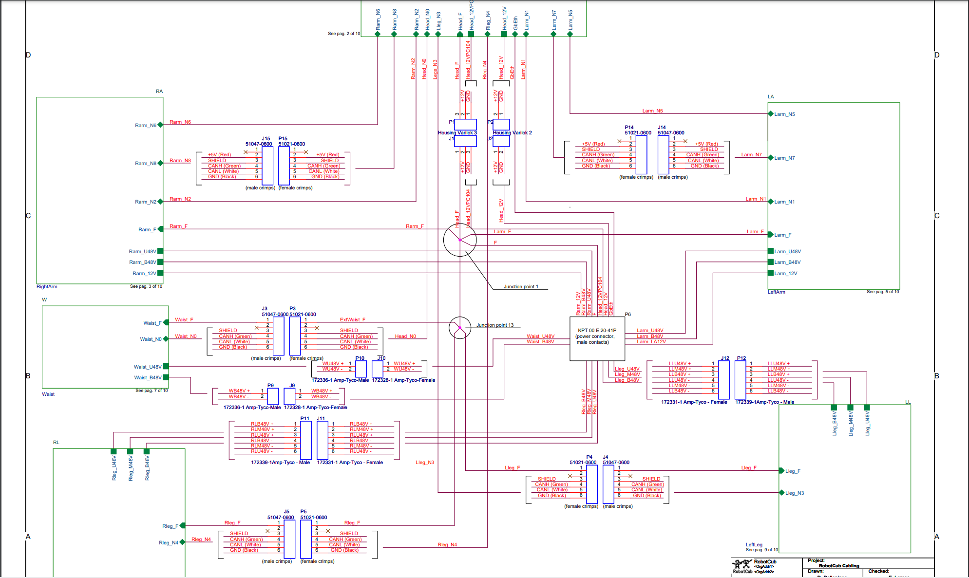
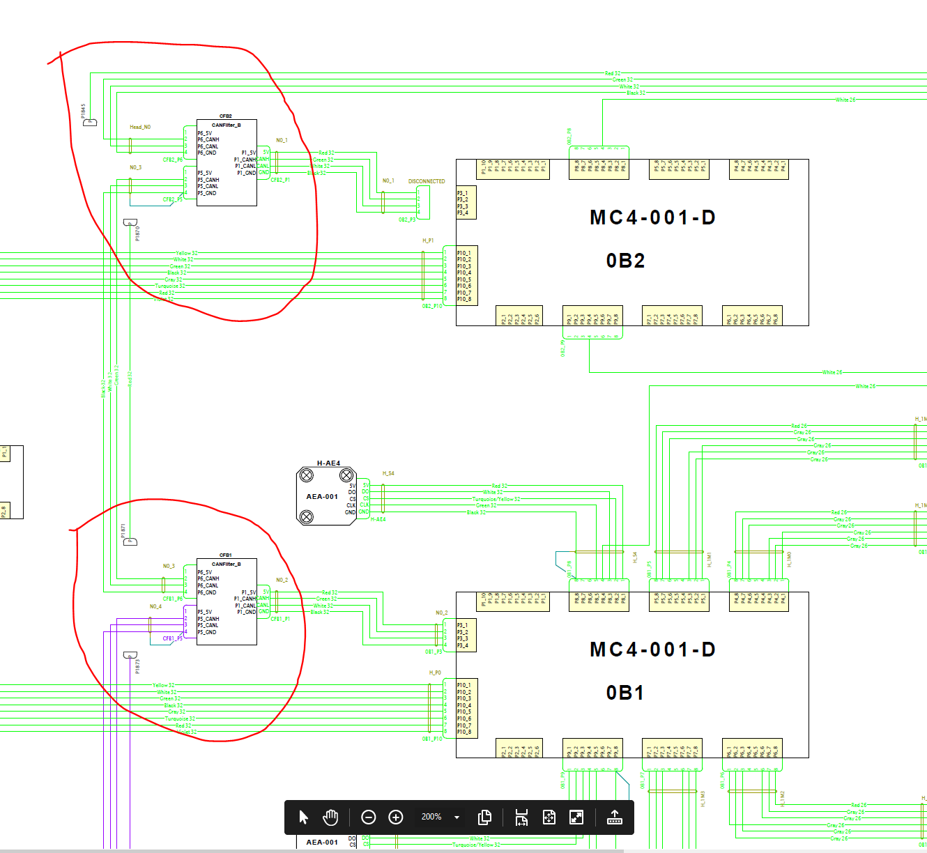
the Can line cfw2 (3) could be the line start from head to the legs, look the N3 on the top of the image i shared below:
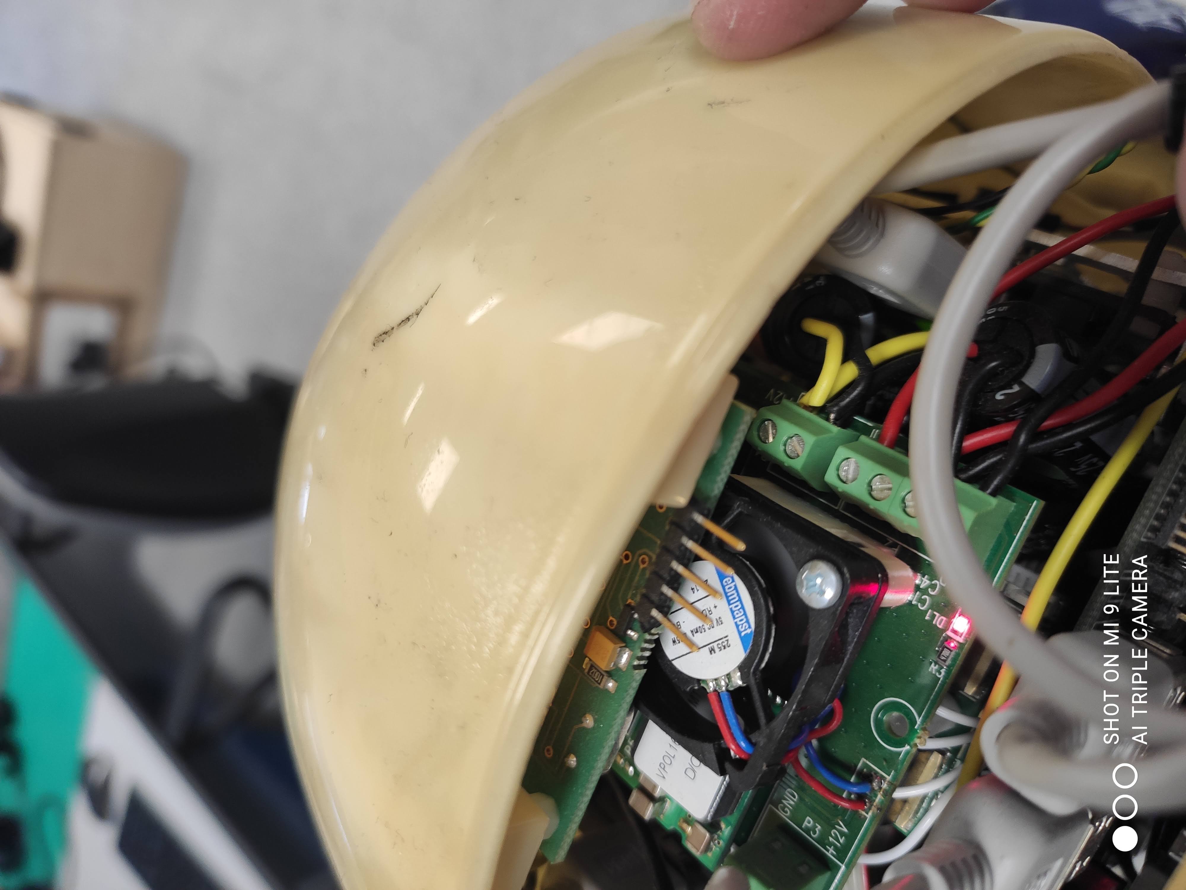
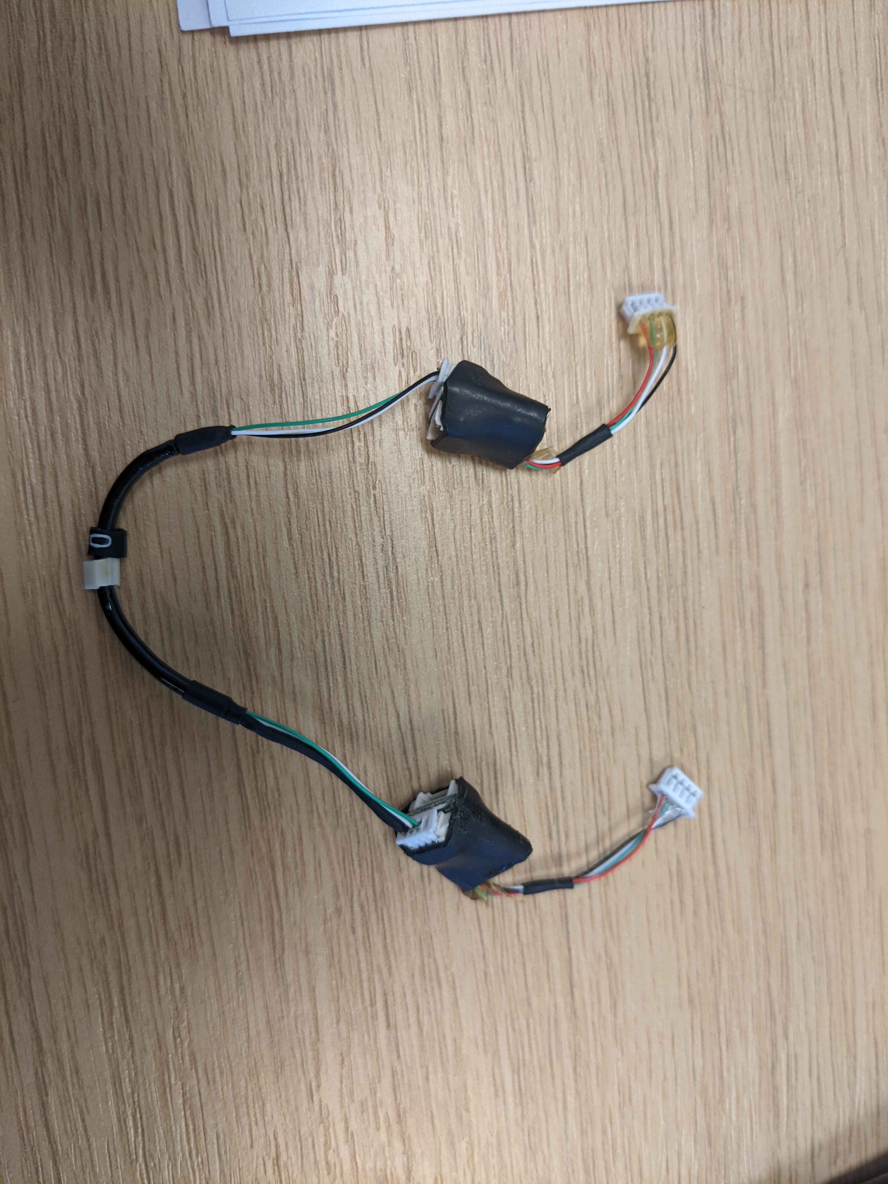
 and below a picture of head can line:
the can is the line with the colors green-black-white and sometimes you will see also the red wire:
and below a picture of head can line:
the can is the line with the colors green-black-white and sometimes you will see also the red wire:
Hi @Uboldi80, I tested the cable of the head CAN, it seemed to be working fine. However, after plugging everything back together, now the pc104 does not start anymore!
More specifically, it stopped answering to ping, and nothing happens when I try to turn it on with a VGA screen attached.
Do you have any idea how to troubleshoot that?
Here are a few pictures, in case you spot something I missed:
Hy Cedric
are you sure that the VGA cable are good? if you are sure, you can try to remove the usb key in to the head and turn on the cpu with the monitor connected. In this case you can see the Bios? let me know
Hi @Uboldi80,
Sorry for the delay, I was away last week. I checked the VGA cable and the monitor, both work fine. However, I still wasn't able to get anything when turning the PC104 on, either with the USB or without.
I unplugged it and tried again, but no luck. Here is how I plugged the VGA cable: icub_vga.pdf
I also unpluged the pc104 from everything else, powered it using a 5V DC source with just the VGA plugged in, and it still did not work.
Do you have any suggestions on how to troubleshoot this?
Hy @cedricgoubard
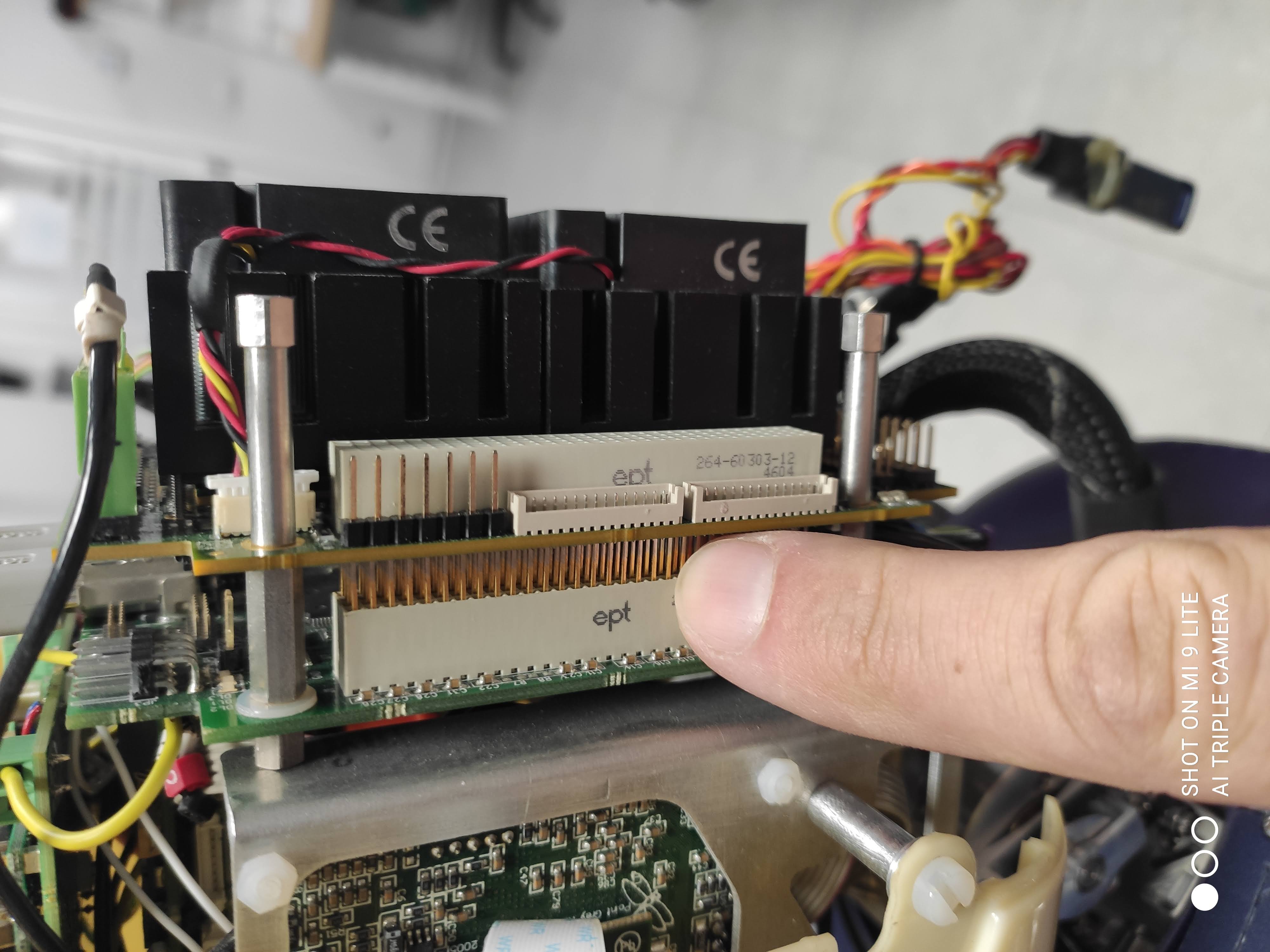
try to check if the pc-104 is connected well trough your connector in the left side.
try to remove and reconnect.
 Another possibility is that the RAM mounted in the pc104 doesen't work, but to check this, it's a bit more complicated.
for now, try to check the pc 104
Another possibility is that the RAM mounted in the pc104 doesen't work, but to check this, it's a bit more complicated.
for now, try to check the pc 104
Hi @Uboldi80,
I tried disconnecting the pc104 and reconnecting it, but nothing changed. Since this happened after I worked on the 4 boards above the IMU, maybe it has something to do with the power supply? I checked the connector on the pc104 and it delivers 2 x 5.35V, but maybe I'm missing something?
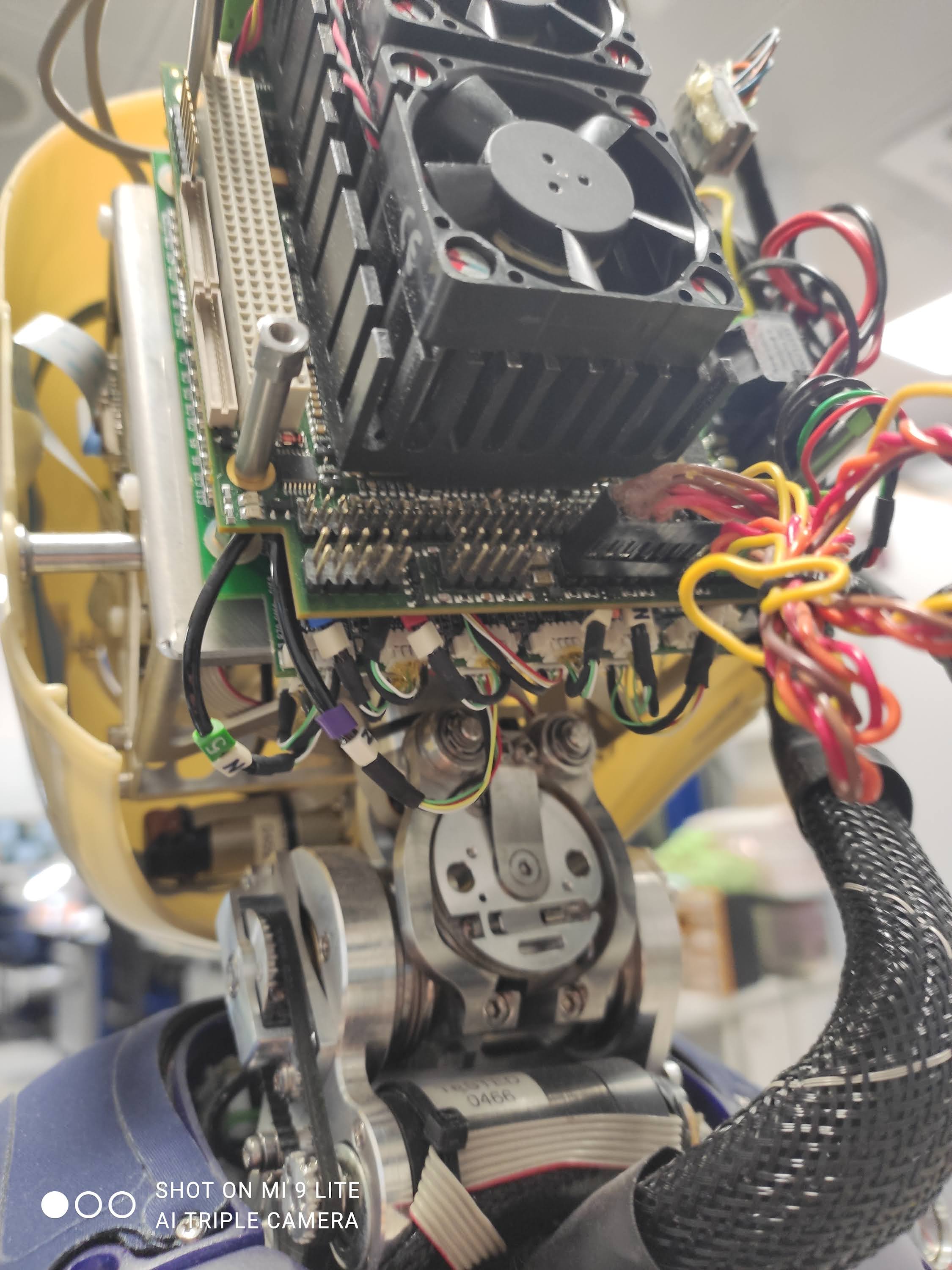
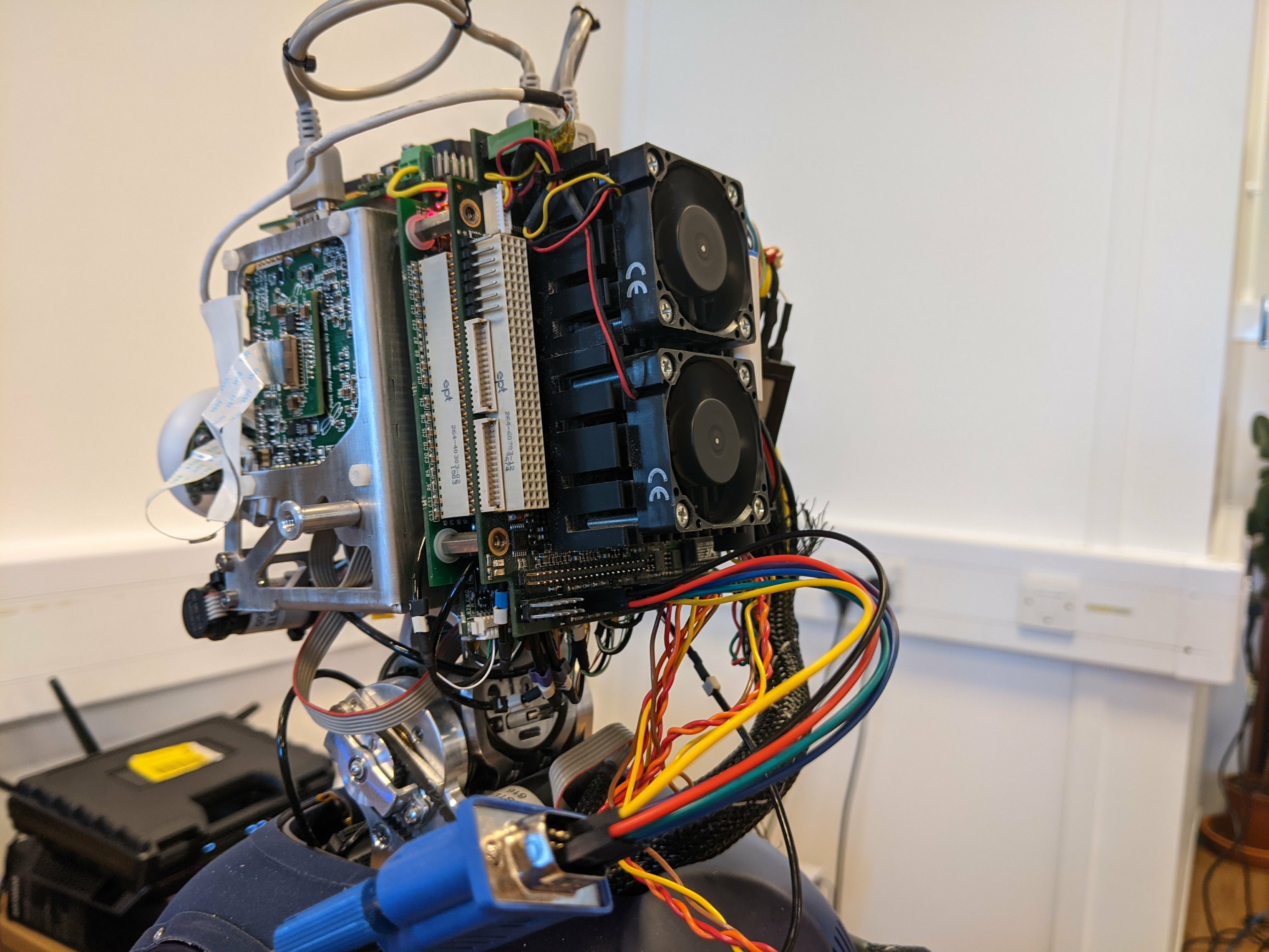
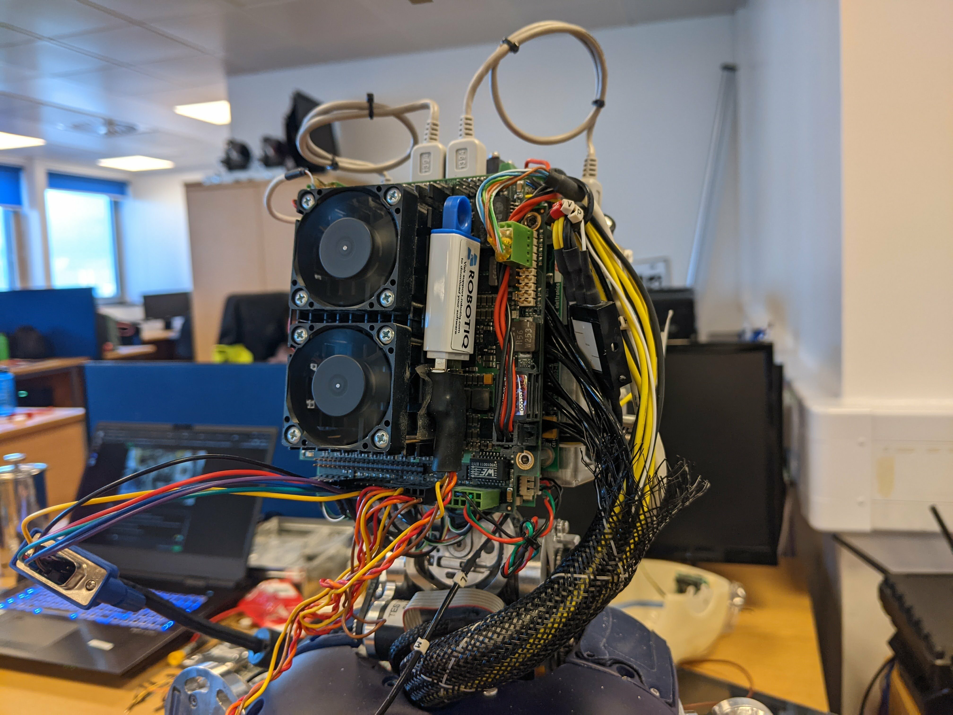
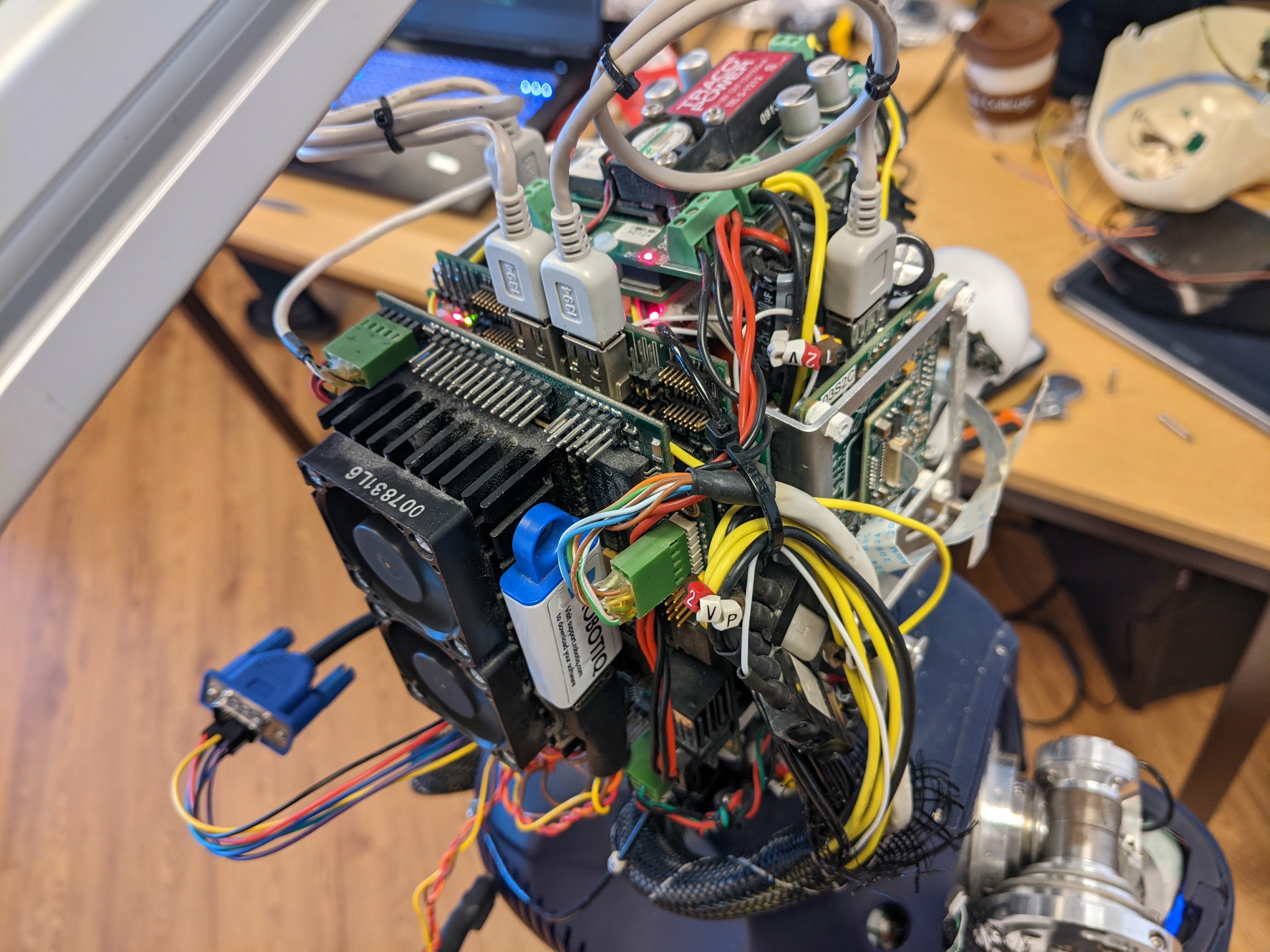
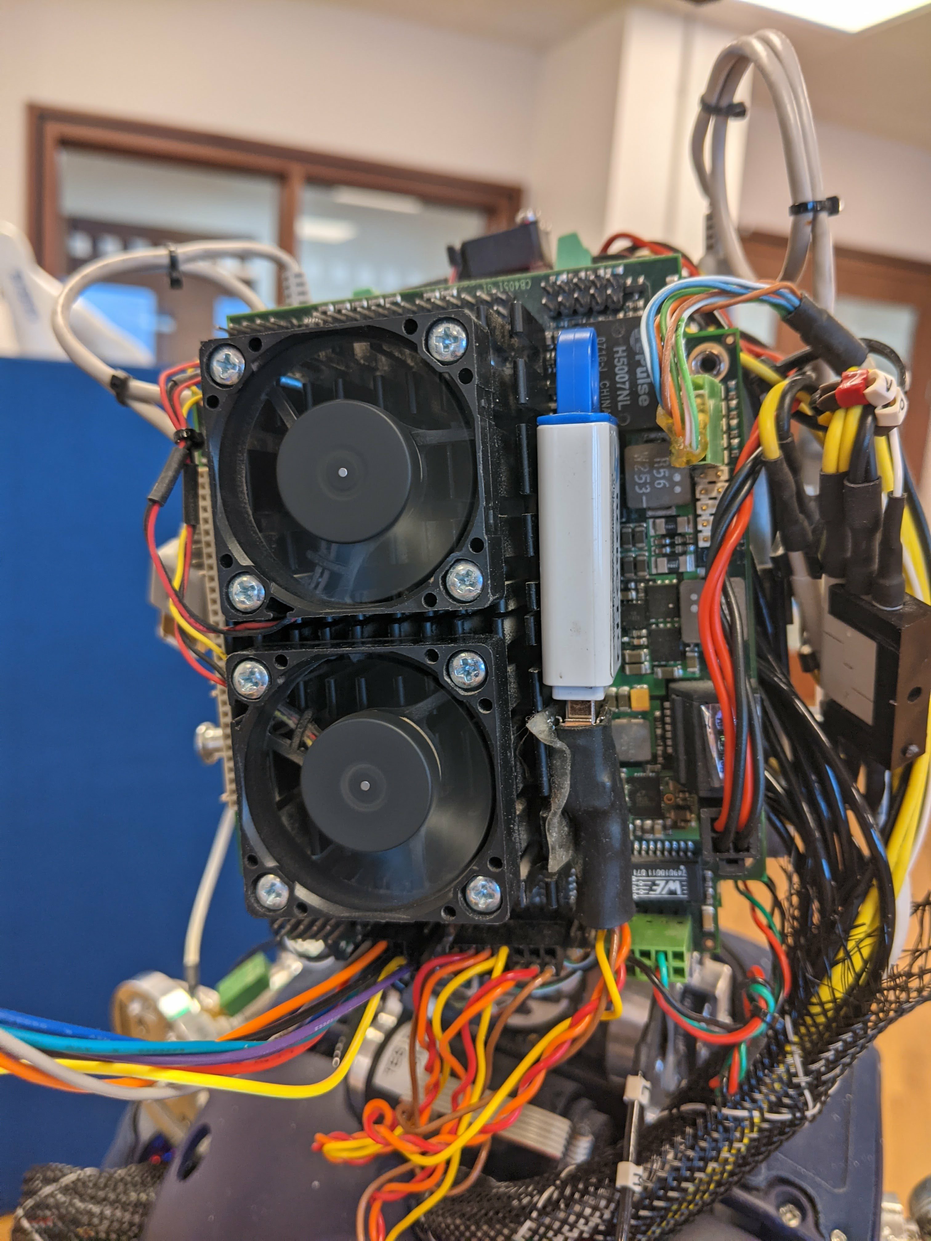
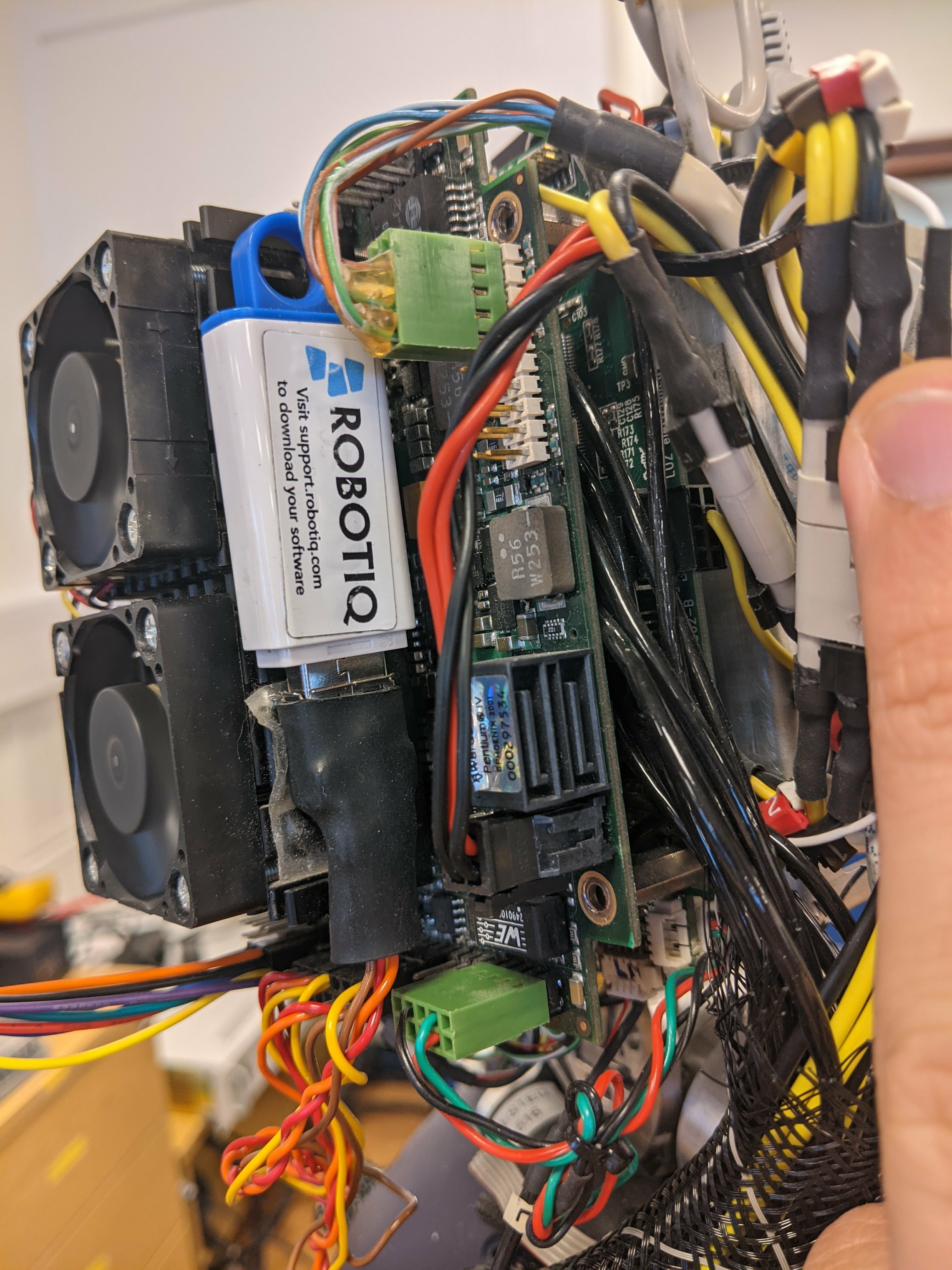
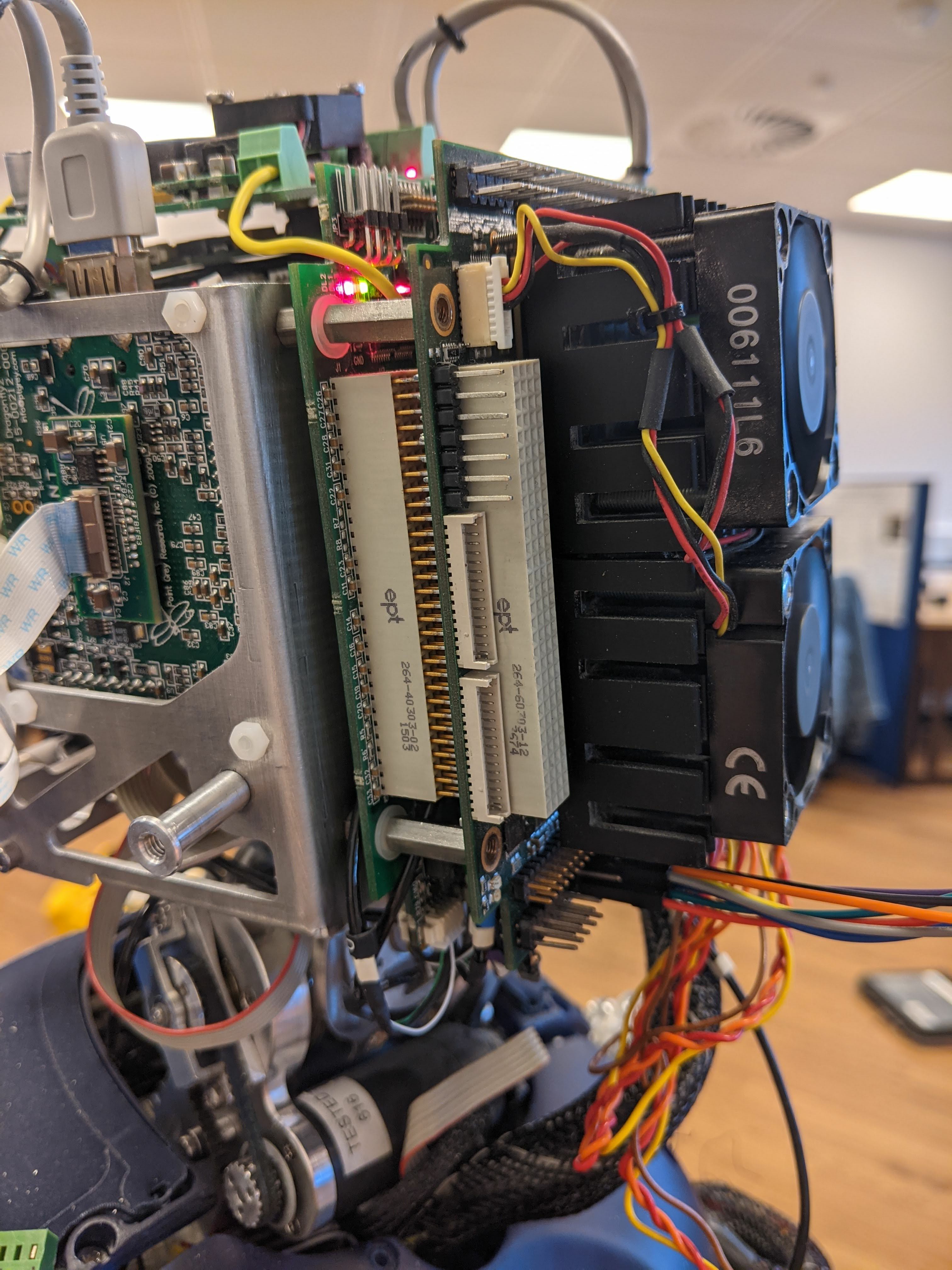
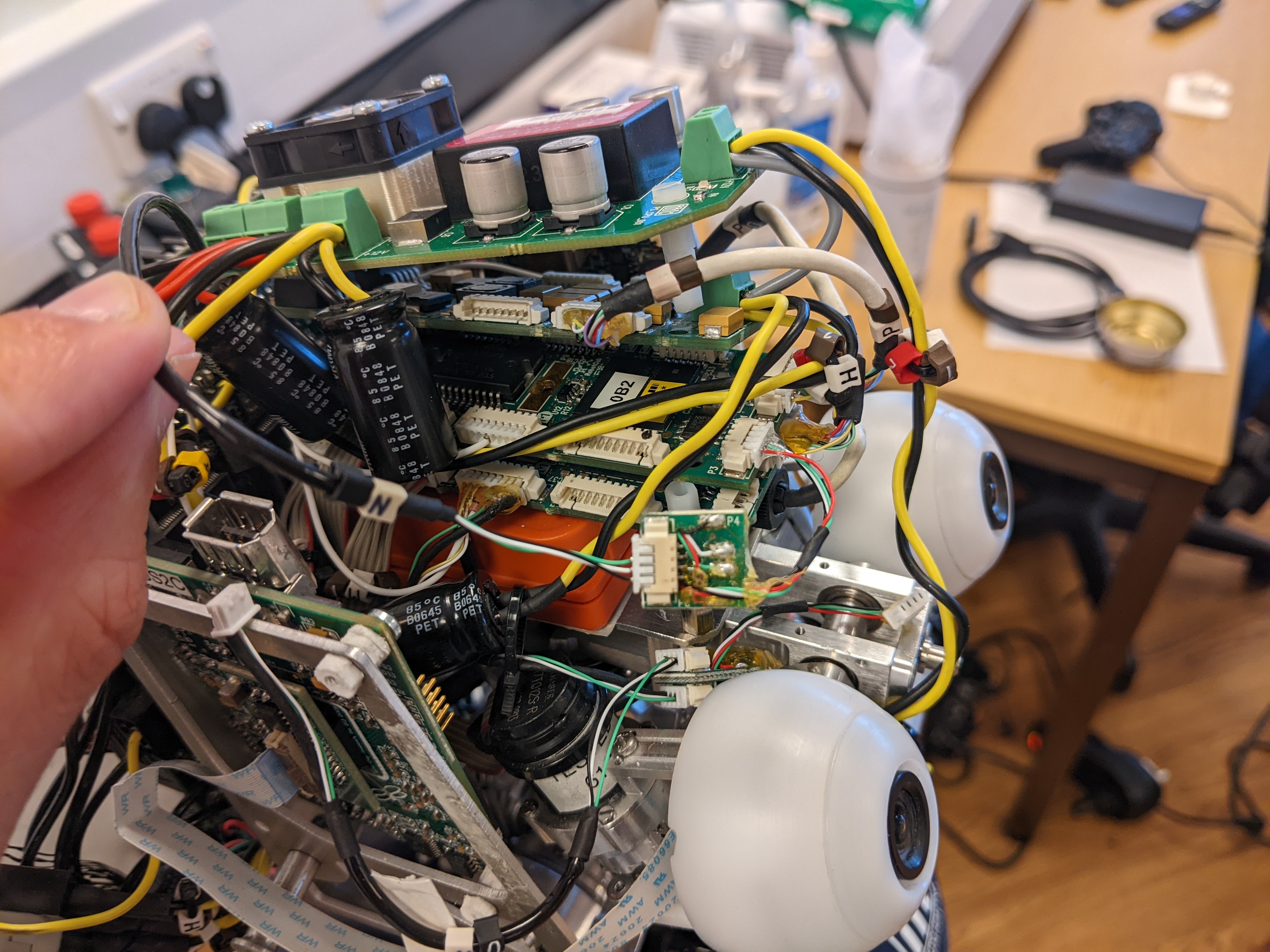
I also noticed that the top board on the head has a red light on, and the pc104 has no lights at all, if that helps. Here are a few pictures.
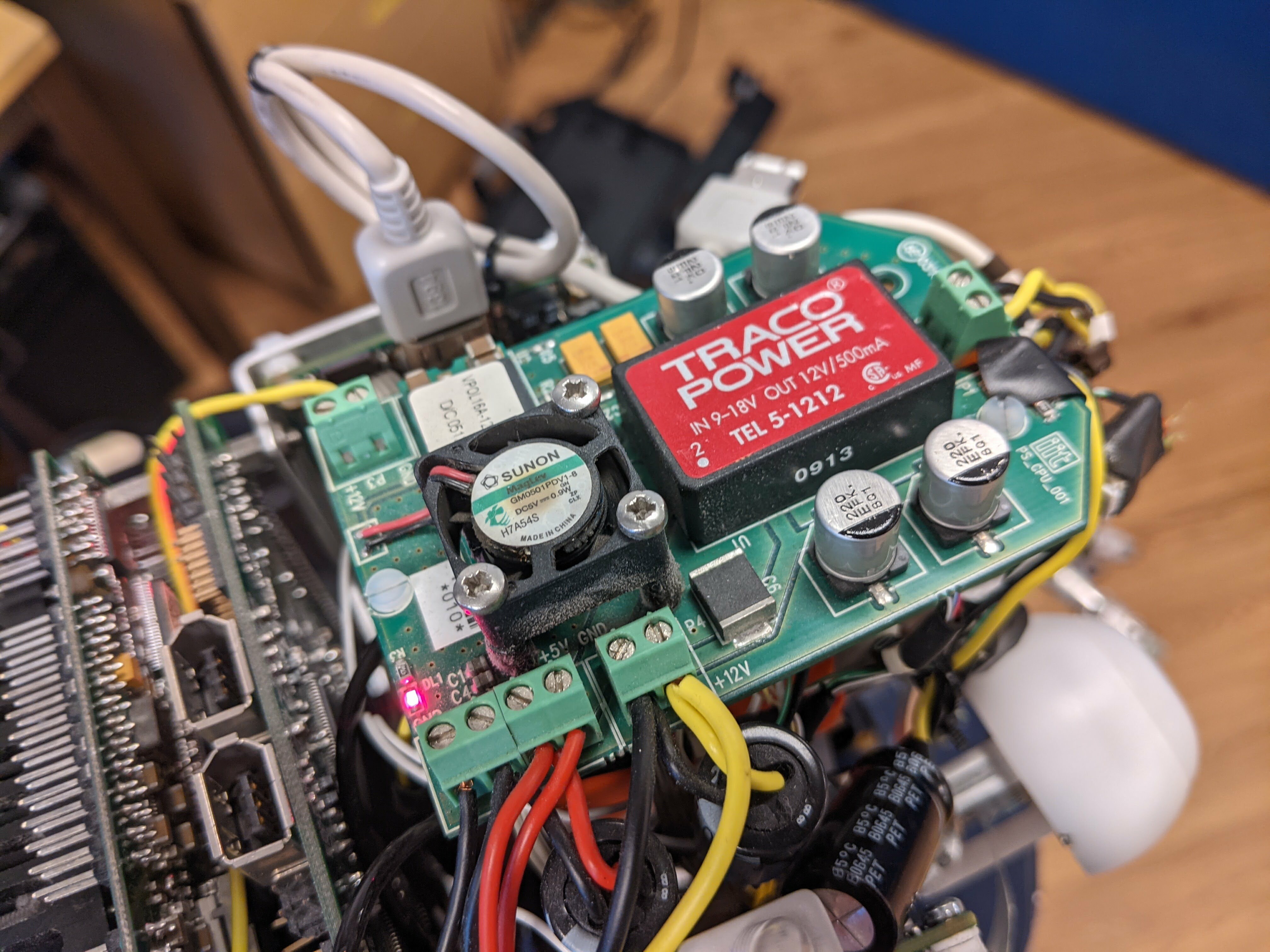
The top board with the red light:
Different shots of the pc104 (edit: I just realised the IMU isn't plugged in on these pictures; I plugged it in, but it still does not work)
Hy @cedricgoubard
verify if from the power supply out yellow and black cables you have 12v PS CPU BOARD (yellow positive)
Hi @Uboldi80, I found 11.8V, so I guess it is working fine. Do you have any other suggestion?
Also, in the meantime, could you tell me how much it would cost/how long it would take to:
- Get a new pc104 (of the same model, if you still have it)
- Send our
iCubback to you for a software/hardware upgrade as @pattacini mentioned in https://github.com/robotology/icub-tech-support/issues/1213#issuecomment-938581251
Thank you again for your help.
Hy @cedricgoubard
we will contact you as soon is possible to provide you the information requested.
Hello,
After a few months, and thanks to the other pc104 you sent us, we identified the reason our iCub was not starting up anymore: the board pictured below has a fault, and randomly stops outputting power.

Would it be possible to order a new one?
Thank you!
Hy @cedricgoubard !
Yes, this is a PS CPU, i can provide to send a new one iit code: 1243.D
cc. @Fabrizio69 @maggia80 @andreaderito
Hi @cedricgoubard I'm about to send you the quotation for the supply of the spare part, it should be ready today (19.04.22), I will transmit via email as usual. cc @Fabrizio69 @maggia80 @Uboldi80
Hi @andreaderito, Great, thank you! I do not think we have received anything yet, I'll let you know as soon as we do.
Hi @cedricgoubard the draft of the quotation is ready (since yesterday) but still pending Scientific Director's signature (I'm going to make a solicit now, so hopefully in short it should be ready and I may send it via email asap) - best
Hi @cedricgoubard quotation sent via email few mins ago - best cc @maggia80 @Fabrizio69 @Uboldi80
Hi @andreaderito, We received the quotation and should be issuing the purchase order shortly.
Hi @cedricgoubard thank you for having confirmed goods received. If you have need for help to install it, pls continue using this issue (not the emails). cc @maggia80 @Fabrizio69 @Uboldi80
Hi,
We installed the new power board, and our pc104 boots again! We are now back to the our issues with the CAN bus. Here is what we have:
And here is everything we noticed so far, based on this documentation:
- We tested the
N0green/black/white wires from theCFW-002to0B0, and the connectivity seems fine - Our robot does not seem to have
CFB0; instead, theN0coning fromCFB1gets plug inP3of0B0, and then exits fromP10of the same board. I think this might have something to do with our long-term issue with the left leg not being detected? - Also,
P3andP10of0B0have 6 pins, not 4. We assumed that the 2 unused pins are the ones on each side for shield, as shown in this image from this issue - Also, our
0B1and0B2were switched; we put them back correctly, but it did not solve the issue. - The documentation seems to indicate that the
N0wire betweenCFB2and0B2should not be connected; however, it was on our robot - The blue and yellow LEDs on the side of
0B2are acting differently from the ones on0B1.0B1always has both LEDs ON, but0B2either has:- the yellow ON and blue OFF when we connect
N0betweenCFB2and0B2 - the yellow blinking and blue OFF when we disconnect them
- the yellow ON and blue OFF when we connect
Also, only one of the two blue LEDs for the motors turns on on the back of the robot; but I am assuming this is unrelated for now, and we will focus on that later.
Since our iCub has been repaired many times over the years, I do not know which of those changes were intentional, and which were not.
Could you please help us understand:
- Are
0B1and0B2interchangeable? - How can we check if they are working correctly?
- Is there anything else we should check?
Thank you for your help!
@roalchaq
Hy @cedricgoubard from this link you can see what you should get from FirmwareUpdater under the various CAN lines. I would say that there are several problems to be solved. https://icub-tech-iit.github.io/documentation/icub_firmware/associated-firmware/associated-firmware/#icub-v2 Are 0B1 and 0B2 interchangeable? generally the boards of the same type are interchangeable, obviously paying close attention to the can address of the same. How can we check if they are working correctly? It is almost certainly not a problem of electronic boards, but of interruption of the CAN lines Is there anything else we should check? Interruptions of the can lines almost always occur when they arrive at the can filters and branch out onto the various boards. Always check the can lines by lightly pulling the cables to verify that there is actually contact between the cable and the connector crimp. usually after years (as in your case) the can cables tend to cook right on the connectors. today I try to verify in which points you could have problems.
Hi @Uboldi80,
Thank you for answering so quickly.
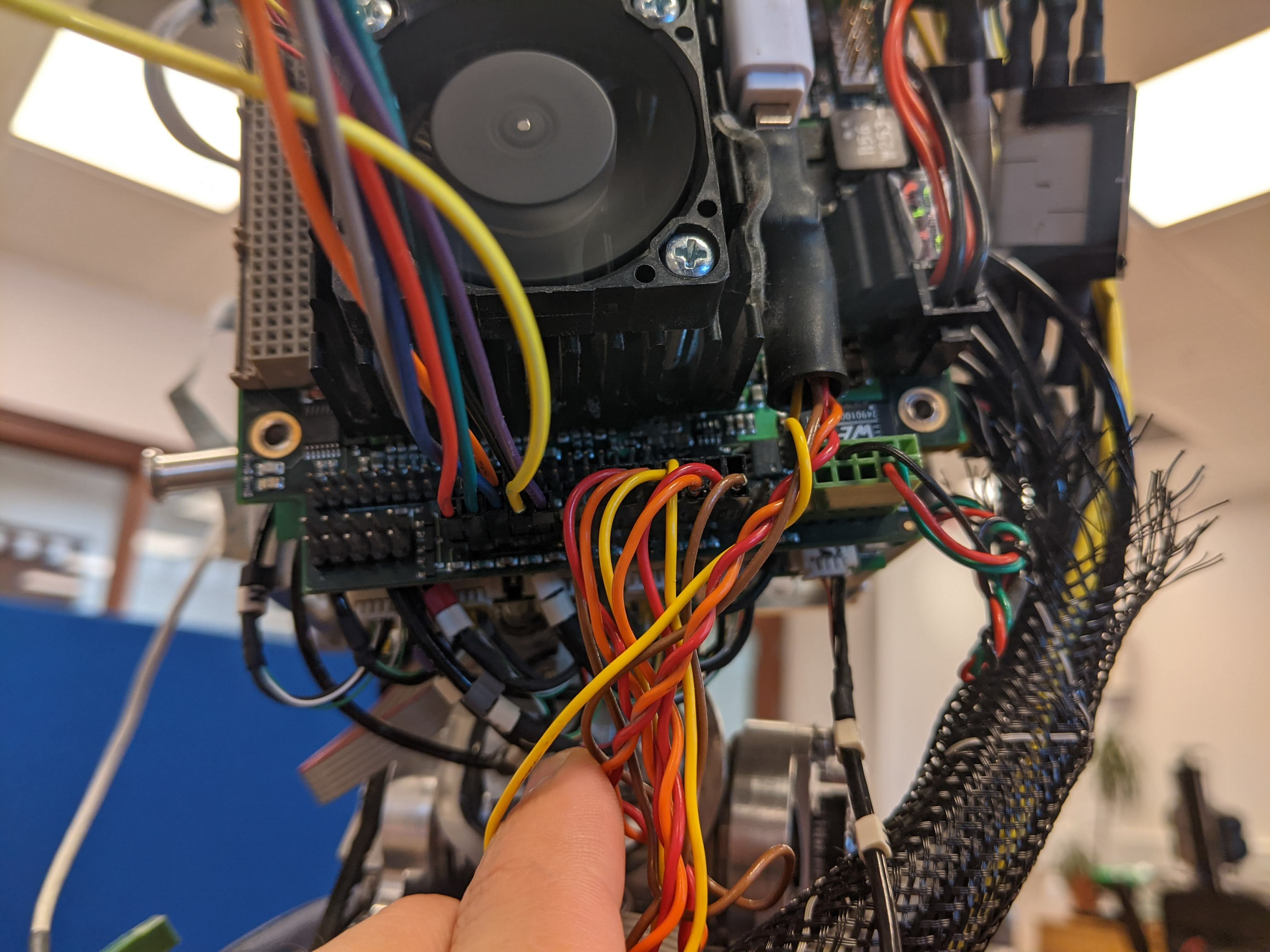
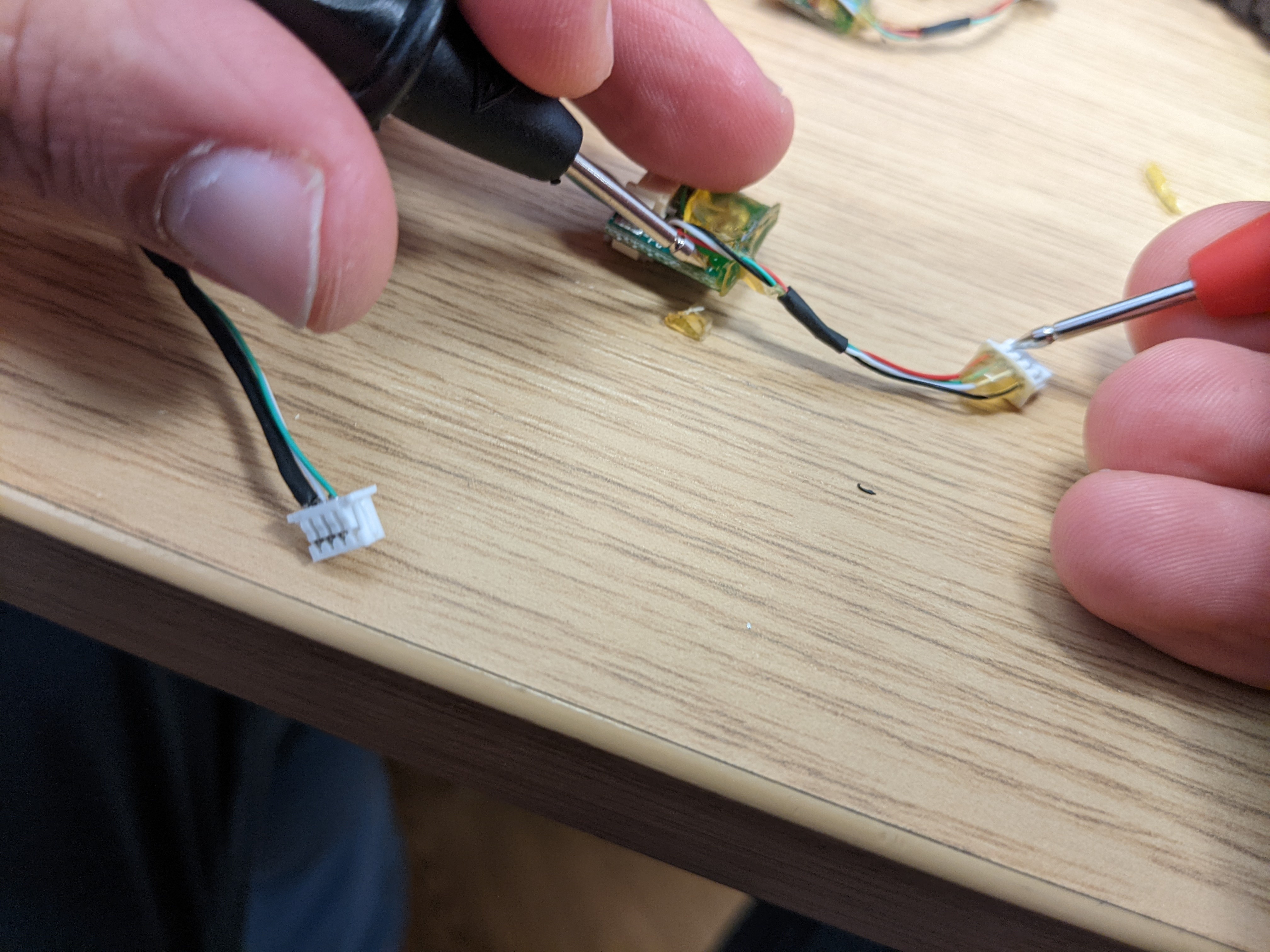
We just checked the connectivity again: for each small wire in N0 (black, green, white), we touched the connector on the CFW board and the other end on 0B1, and on 0B2 (see pictures).
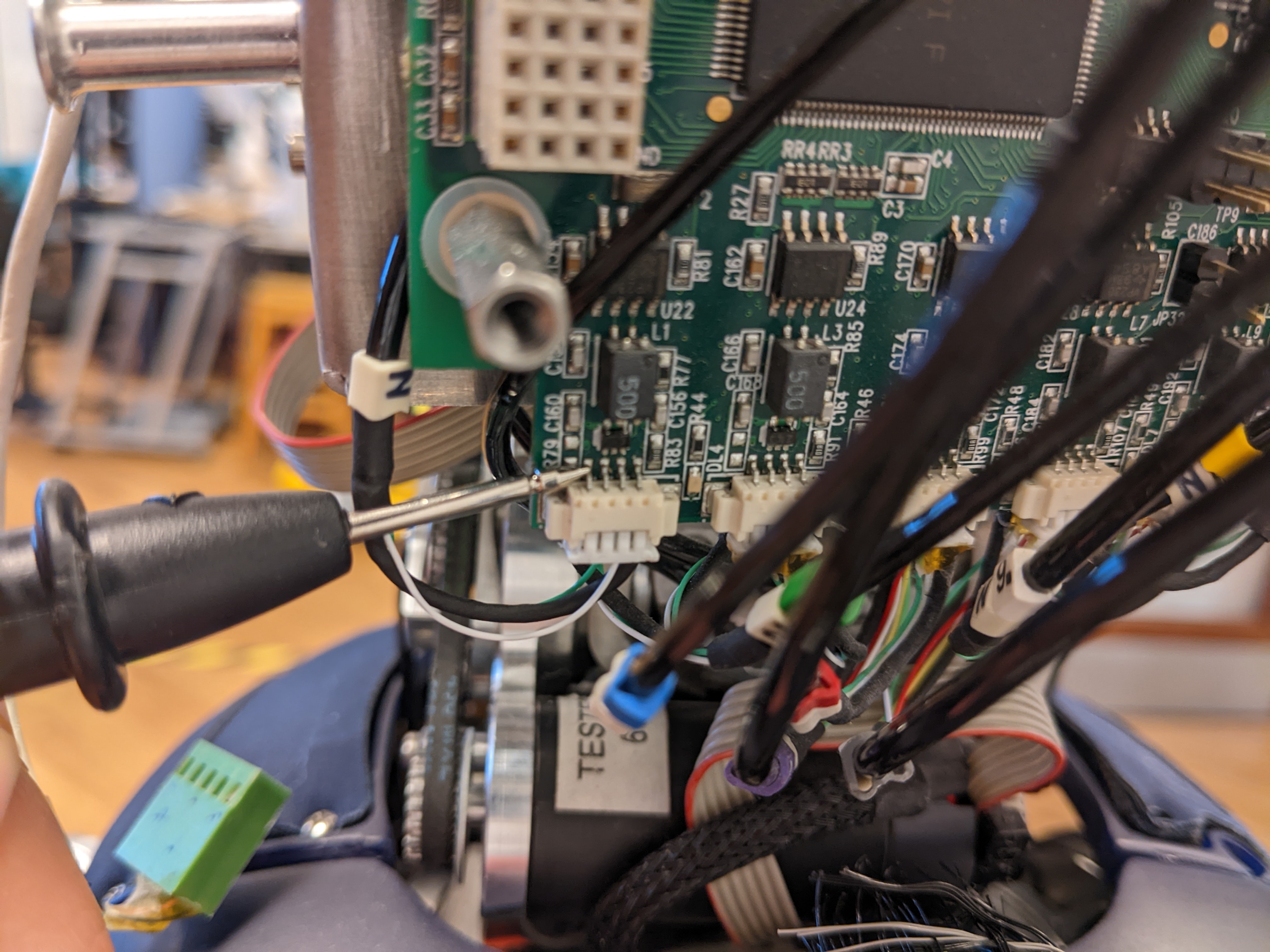
Everything seems to be working fine... Let me know if you think of any other check we could do.
Also check the connector on the side that manages the power supply if I'm not mistaken. pull lightly with tweezers each of those colored cables on the connector.
I checked the two CAN filtersCFB1 and CFB2:
As far as I can tell, they are both getting 5V from their respective boards.
I also tried different connections: (not sure it should change anything, but just in case):
CFW->CFB1->0B2same errorCFW->CFB2->0B2same errorCFW->CFB1->0B1same errorCFW->CFB2->0B1same errorCFW->0B2same errorCFW->0B2same error
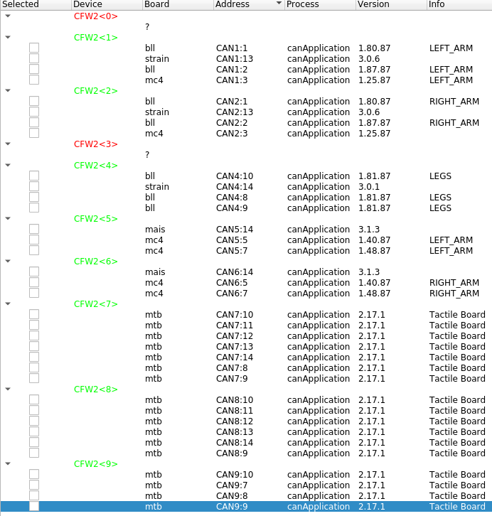
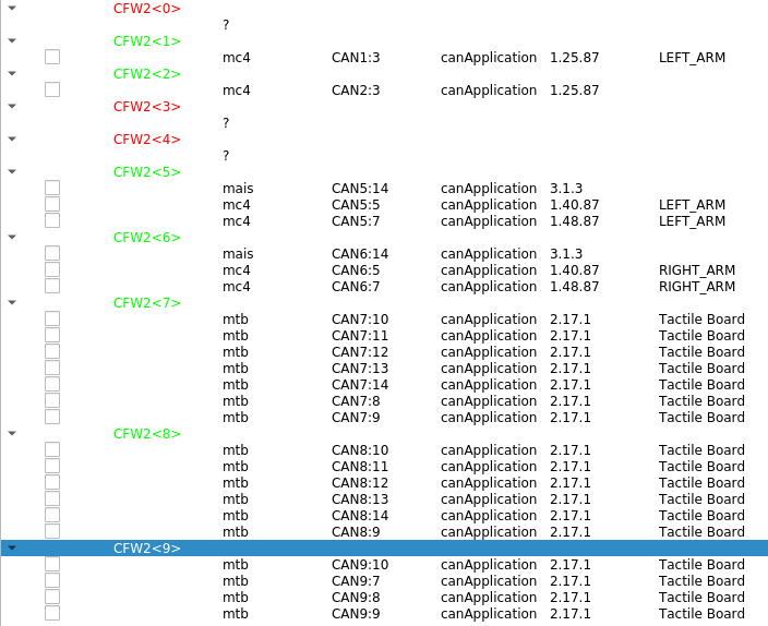
Here are the logs I always get from FirmwareUpdater:
icub@pc104:~$ FirmwareUpdater
Using default address  10.0.1.104
Using default port  3333
"CFW2" - "0"
"CFW2" - "1"
"CFW2" - "2"
"CFW2" - "3"
"CFW2" - "4"
"CFW2" - "5"
"CFW2" - "6"
"CFW2" - "7"
"CFW2" - "8"
"CFW2" - "9"
ACE_SOCK_Dgram: Cannot assign requested address
ACE_SOCK_Dgram_Bcast::mk_broadcast: setsockopt failed: Operation not supported
ACE_SOCK_Dgram_Bcast: Operation not supported
libGL error: No matching fbConfigs or visuals found
libGL error: failed to load driver: swrast
[INFO] |yarp.dev.PolyDriver| Created device <cfw2can>. See C++ class yarp::dev::Cfw2Can for documentation.
FirmwareUpdaterCore::getCanBoardsFromDriver(): No answer received from CAN boards after a successful driver init.
[INFO] |yarp.dev.PolyDriver| Created device <cfw2can>. See C++ class yarp::dev::Cfw2Can for documentation.
FirmwareUpdaterCore::getCanBoardsFromDriver(): No answer received from CAN boards after a successful driver init.
Did you also check this filter on the CAN chain? check on the entire length of the can chain, therefore, arrival and departure for all 3 boards on the head.
I think you forgot to include a picture; I assume you mean CFB0?
In our case, I did not find this filter on the robot... It looks to me like P5 on CFB1 is connected directly to P3 on 0B0. Then, it looks like another CAN line comes out of P10 on 0B0 and goes somewhere in the back of the robot.
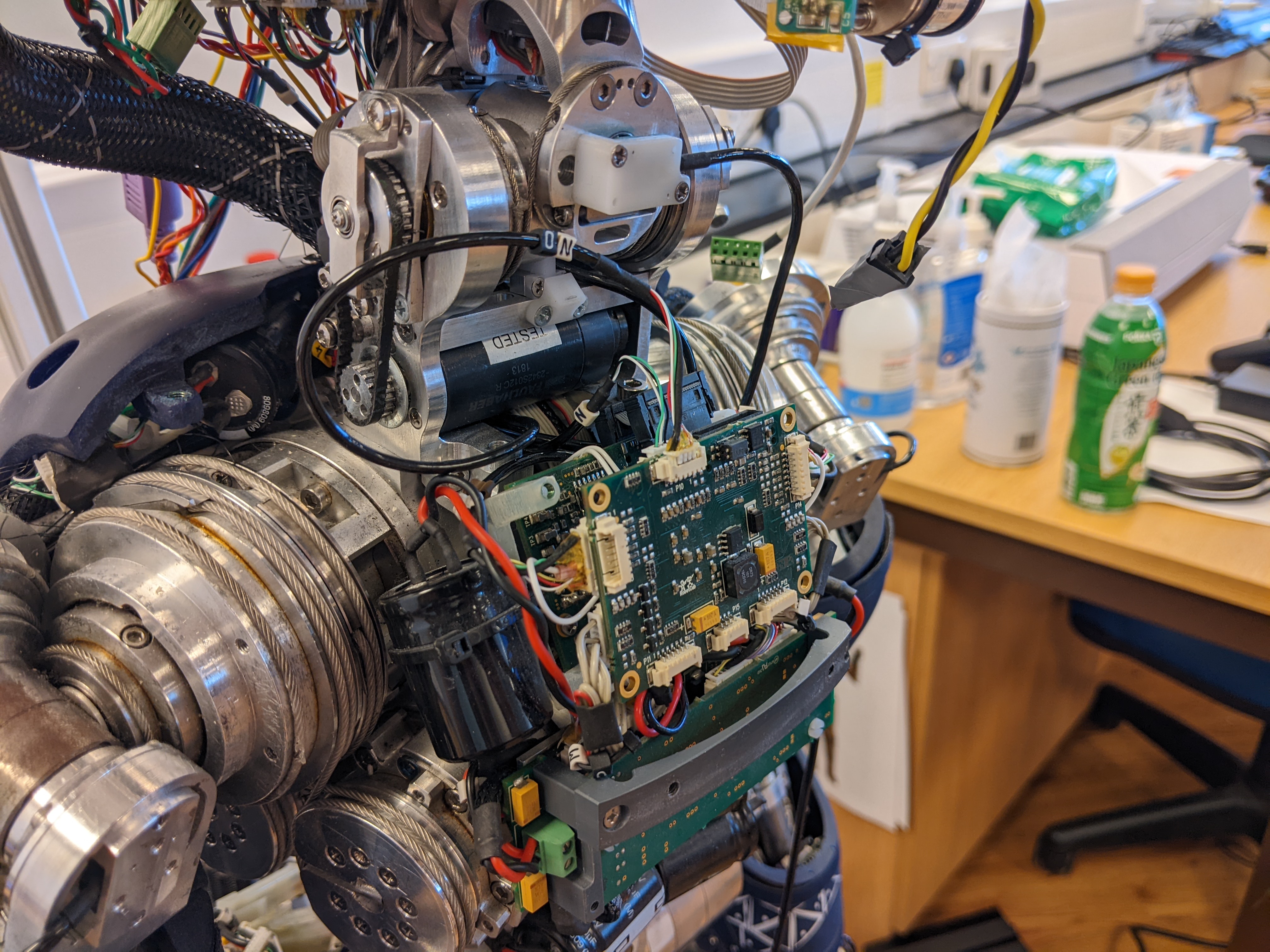
On the picture, you can see the N0 wire with only black/white/green that comes from the neck and gets plugged in the back of the 0B0 board (P3). Then, another N0 (this time including a red wire) comes from the front (P10) and goes back in the neck.
Also, the documentation only mentions 4 pins on P3 on 0B0, but ours has 6.
Ok, this is the picture of BLL 0B0:
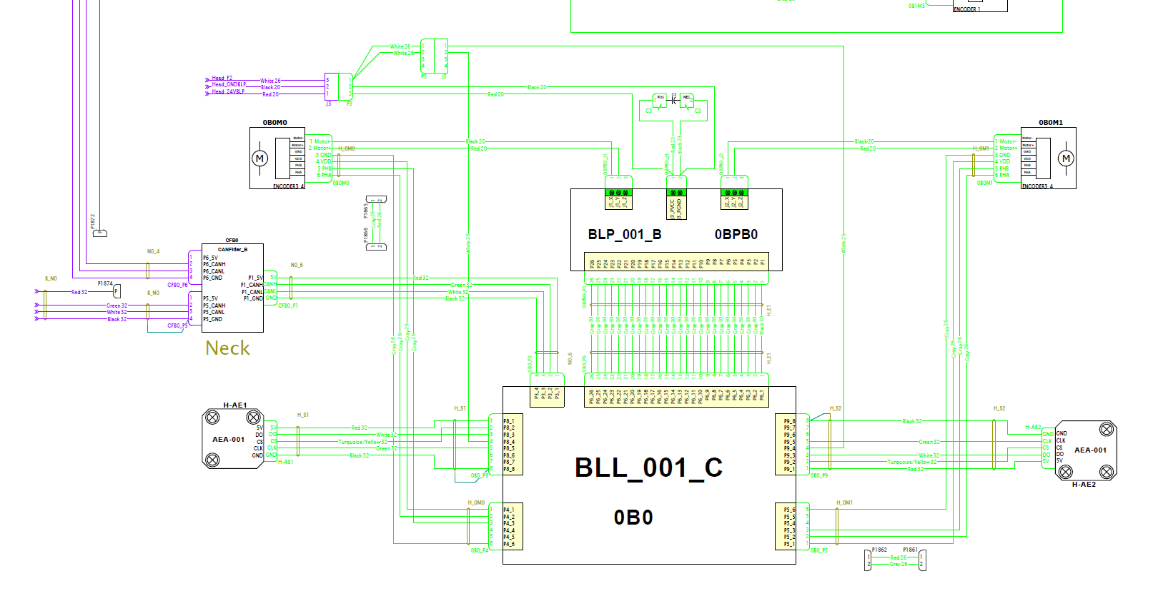 As you can see we have a can line in position P3 until a can filter CFB0
Could you tell me where CFB0 is supposed to be on the robot? I cannot find it on our iCub.
follow the CAN cable which starts from the P3 of the BLL and which should be identified as N06. that cable should flow into a can filter (CFB0). Since you have the BLL in sight, also check that the FLAT CABLE between the BLL and the BLP is well inserted.
Hi @Uboldi80,
I just checked again: on our robot, the N0 cable coming out of P5 on CFB1 is plugged directly in P3 on 0B0: there is no CFB0...
Would it be possible to order some new 0B0, 0B1, 0B2, CFB0, CFB1, CFB2, and N0 wires?
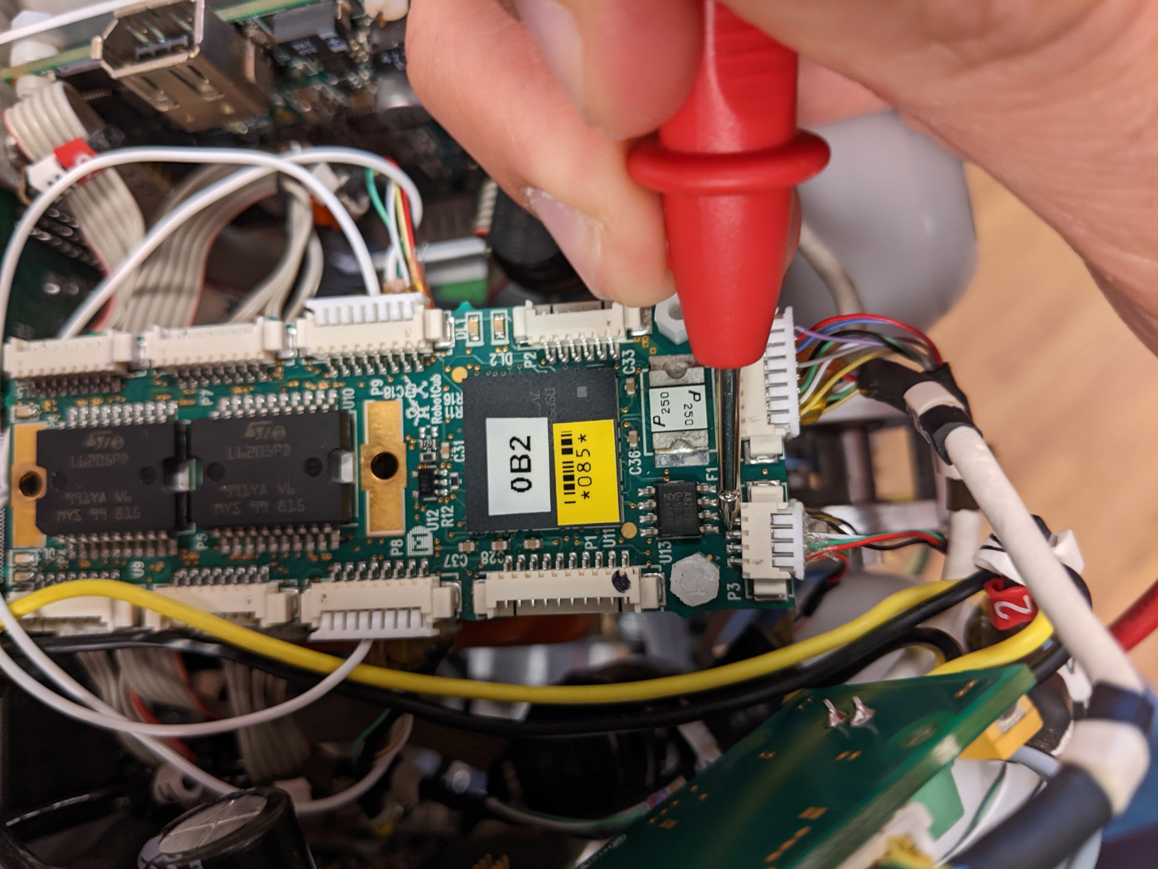
Hi @cedricgoubard, please can you try to center the connector in this picture?
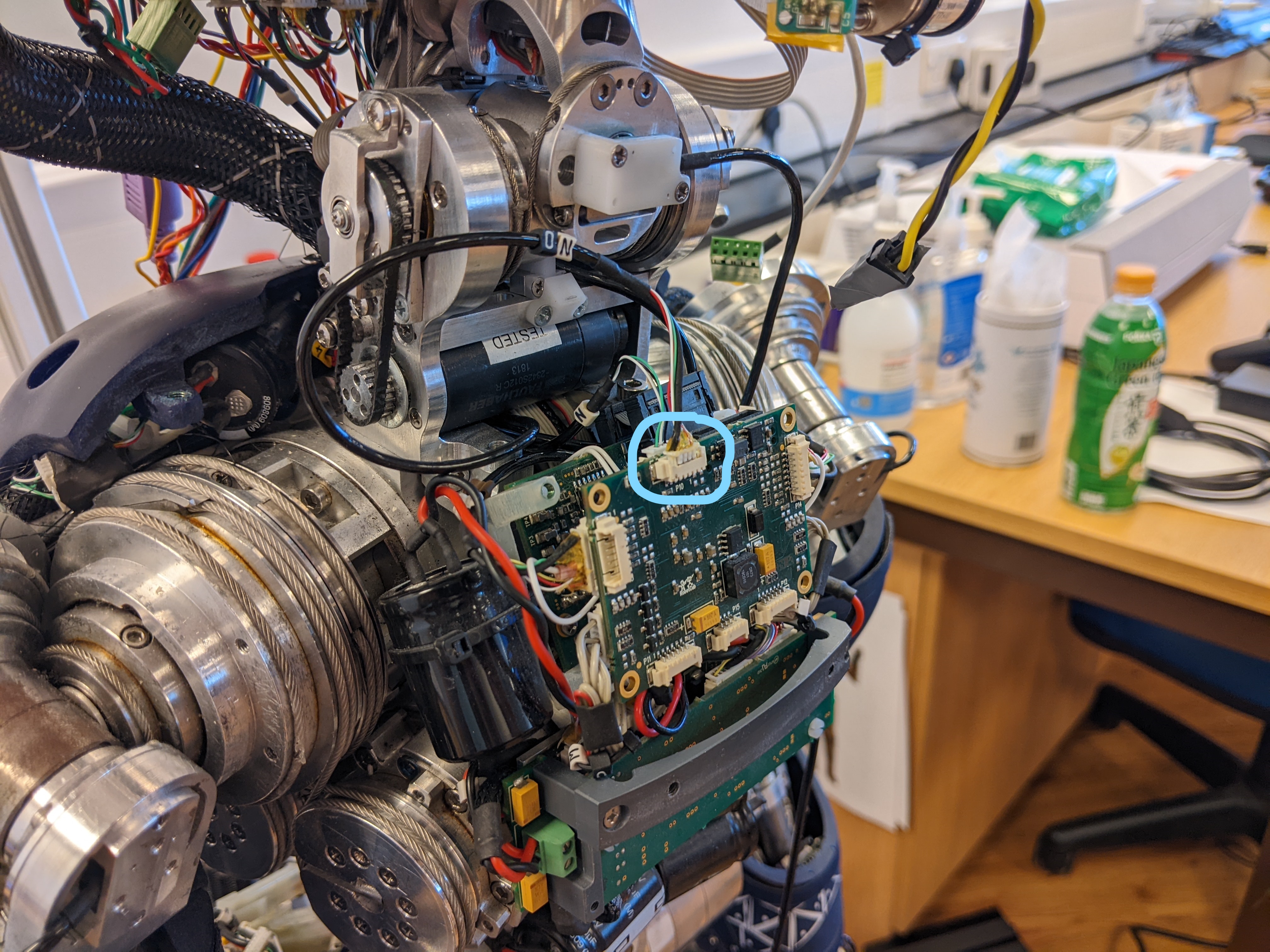
From what I see now is aligned on one side, you should leave one pin free on the left side and one on the right side.
Thanks!
cc @Uboldi80