blog
 blog copied to clipboard
[S32K344] HSE Overview
1. SECURITY ARCHITECTURE
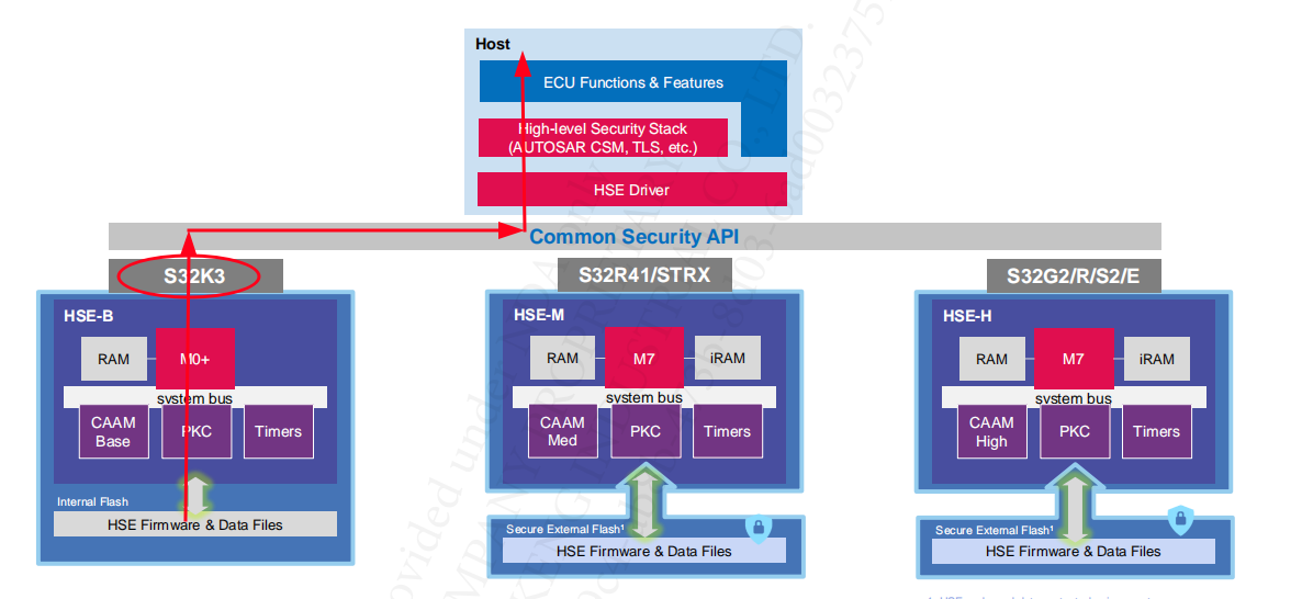
Architecture:
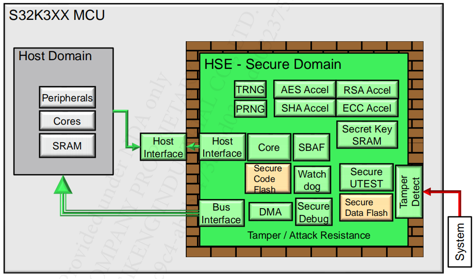
Functional Blocks:
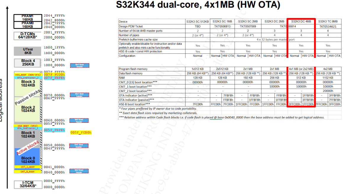
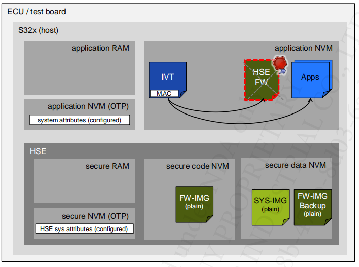
2. Memory Architecture For HSE
3. HSE Boot Artifacts (IVT/HSE FW)
The secure boot flow involves multiple software bootloaders – this gives a great deal of scope for customisation to ensure that boot process is optimal for specific use cases.
3.1 Boot Flow
From a high level, the flow is as follows:
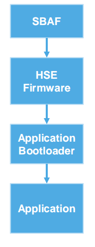
- SBAF (Secure Boot Assist Flash) Installs and boot HSE FW.
- HSE firmware then authenticates customer bootloader(s):
- Authenticate the Application Bootloader to SRAM based on Core Reset (CR) and Secure Memory Regions (SMR) configurations
- Hand control to Application Bootloader(s) executing on selected core
- Application Bootloader begins execution
- Application Bootloader then starts the Application(s)
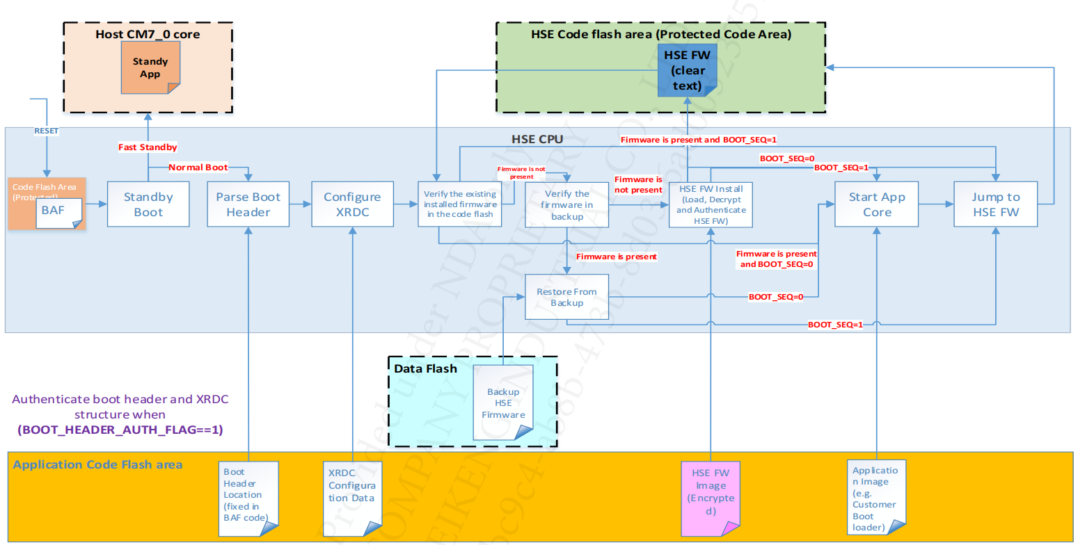
Depending on configuration inputs, the HSE can handle:
- HSE Firmware install. The pointer to HSE Firmware encrypted and signed image is in IVT or the firmware image can be placed at the first IVT location.
- Unsecure Application Boot (HSE FW not used). The App Start pointer(s) are provided in IVT (see IVT from next slides)
- HSE Firmware boot. HSE FW is installed as plain text in secure flash. During device configuration one can also import the keys and secure boot information in the device.
Note, The Application Secure Boot is managed by HSE FW through:
- Core Reset (CR) and Secure Memory Region (SMR) services (also called SMR based boot)
- Basic Secure Boot (BSB) – only one core can be booted and the application is signed via “HSE Boot Data Sign” service.
- Signing of boot artifacts: IVT image. This is can be done using “HSE Boot Data Sign” service
3.2 Boot Image
The layout of the Boot Image binary in the flash of the chip is shown in following figure:
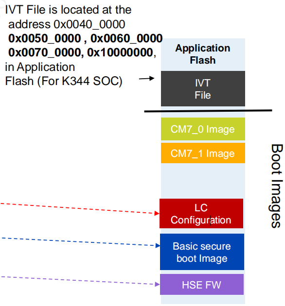
IVT + Core0 image + Core1 image + LC config + Secure Boot image + HSE FW.
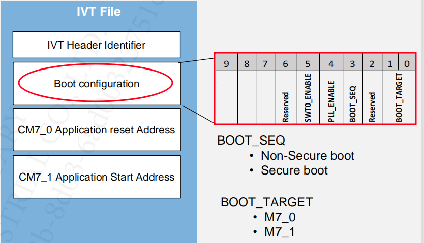
3.2.1 Image Vector Table (IVT)
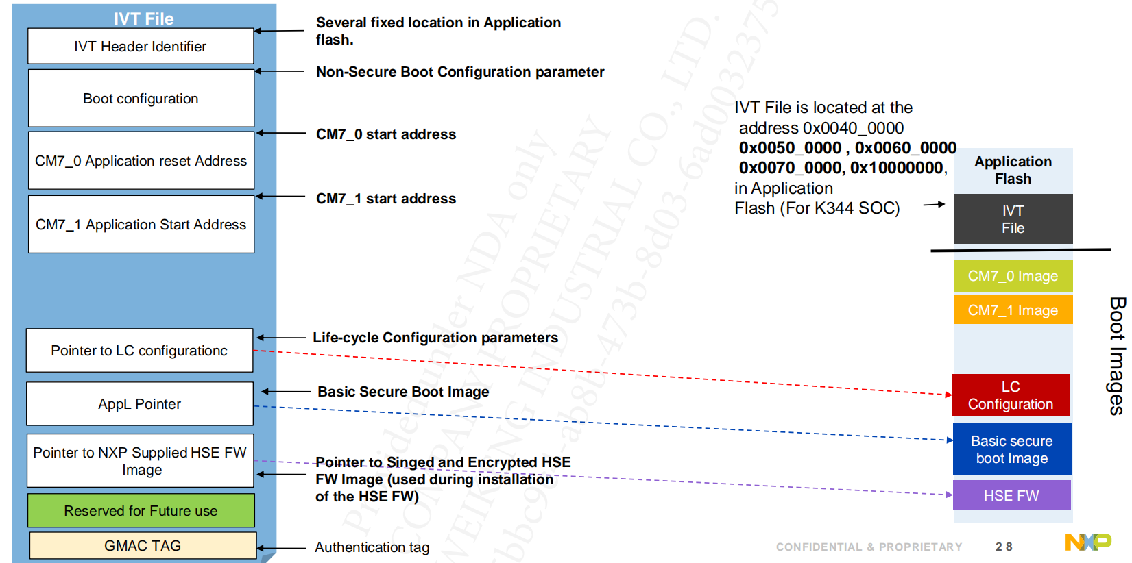
IVT used by HSE to Boot application in non-secure way, for configuration and installation, while it is defined by the Application and it signed by the HSE, (only if security is enabled.
3.2.2 HSE Firmware
There are two types of the HSE firmware, which are the pink image and blue image.
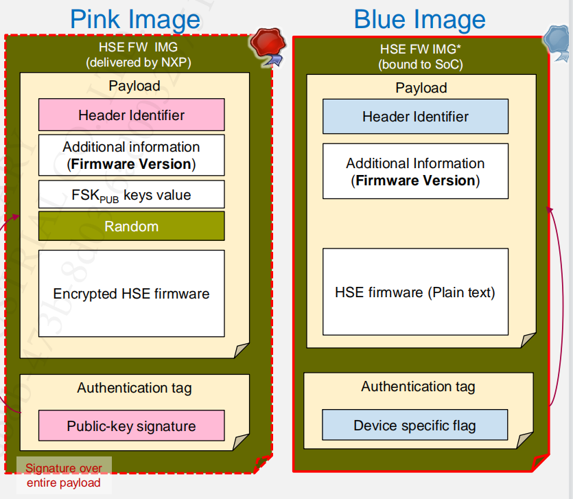
Note, the HSE will be signing the Application. As the result, there is a private key in the HSE firmware. While the HSE also can encrypt the App image by a NXP FW Delivery key (FDK).
Note, the HSE has considered some attacks to enhance the security, such as:
- Installed in plain text inside HSE secure code flash block;
- Protected against rollback attacks
- HSE FW version in Pink Header should be greater than HSE FW version installed on the device.
4. HSE Interfaces
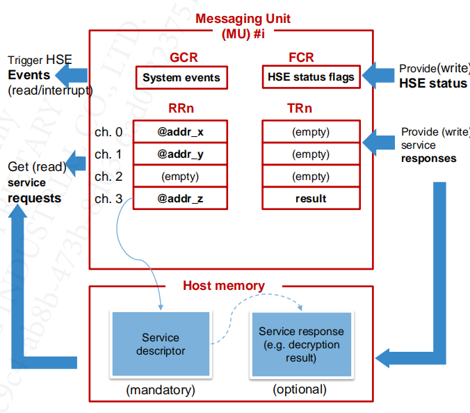
4.1 HSE Message Unit (MU)
AP -> HSE:
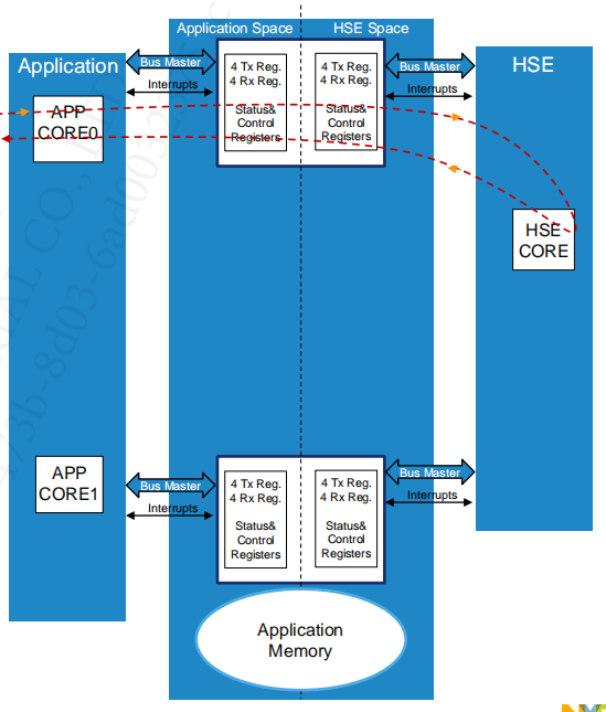
The features:
- Multi-thread access
- Each thread can use one/many physical channel
- Suitable for simultaneously asynchronous requests
- Multi-process/domain access
- each process can use its own MU interface => isolation (Freedom from Interference )
- By default, only MU0 is enabled. The Application can enable more MUs using “Set Attribute” service
4.2 HSE Service Interface
4.2.1 Host Side
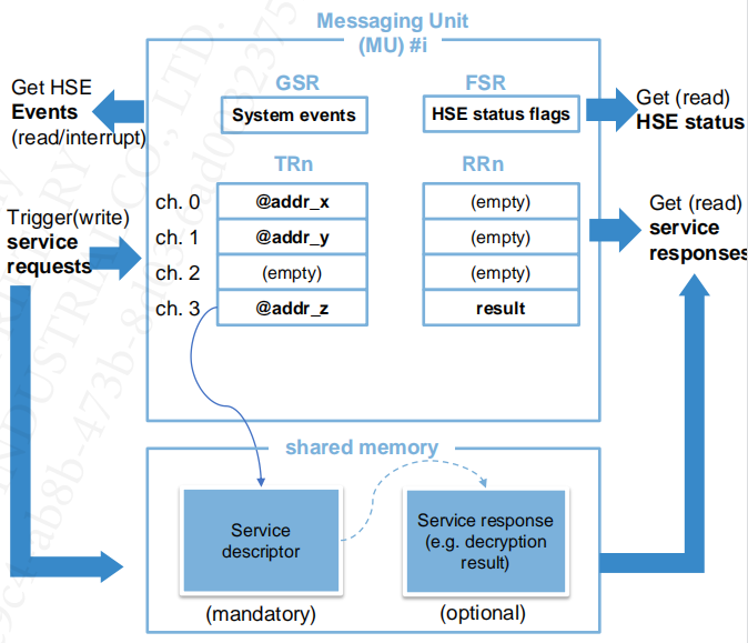
HSE Channel
- Is bidirectional logical communication path from a Host Application to HSE Firmware used to access the HSE services.
- Transports HSE Service parameters and status messages
- Is implemented using MU registers and shared memory
- Categorized in Control Channels (Channel 0) and Data Channels
HSE Mailbox (service descriptor)
- Mailbox stores service parameters
- using Shared Memory
4.2.2 HSE Side
HSE Channel
- Is bidirectional logical communication path from a Host Application to HSE Firmware used to access the HSE services
- Transports HSE Service parameters and status messages'
- Is implemented using MU registers and shared memory
- Categorized in Control Channels (Channel 0) and Data Channels
HSE Mailbox (service descriptor)
- Mailbox stores service parameters
- using Shared Memory
4.2 HSE Service Request/Response
4.2.1 HSE Service Request
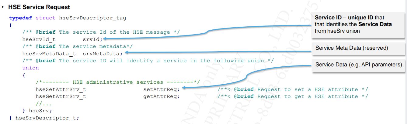
HSE Service Response (hseSrvResponse_t); is provided by the HSE firmware, to indicate the end of a service request. It indicates whether the requested service has successfully completed or ended with an error.
4.2.2 HSE STATUS & NOTIFICATION ERRORS
HSE Status is provided by FSR register:
- HSE Channel Flags (the least significant 16 bits in MUB.FSR register; one bit per channel)
- 0b - channel idle and it can accept service requests
- 1b - channel busy
- HSE Status Flags (the most significant 16 bits in MUB.FSR register):
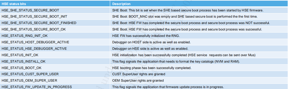
Asynchronous notification errors (at MU level) signaled by HSE to HOST through interrupts (GSR register). Each time a bit is set (an error is triggered) an interrupt occurs. E.g. FATAL ERROR: HSE FW will shutdown the MU communication (APP should perform a system reset).
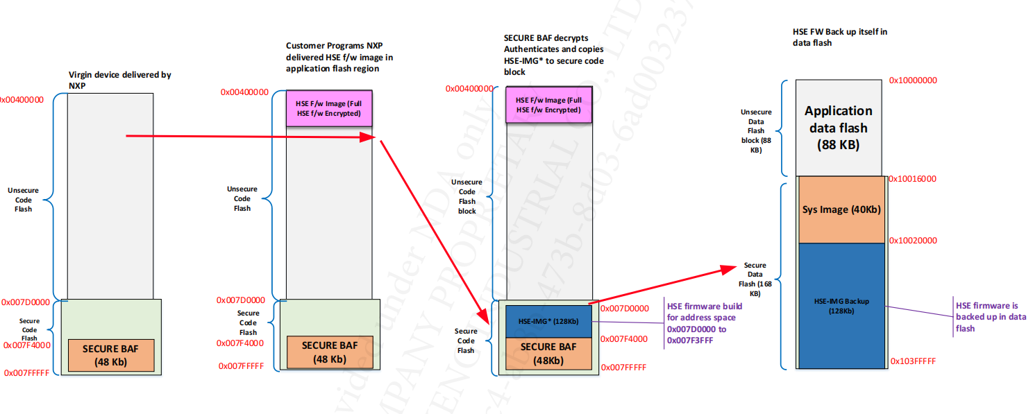
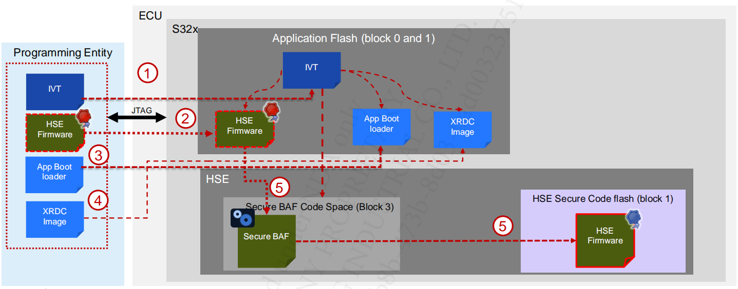
5. HSE Installation on Virgin Device
5.1 Full Memory
After POR:
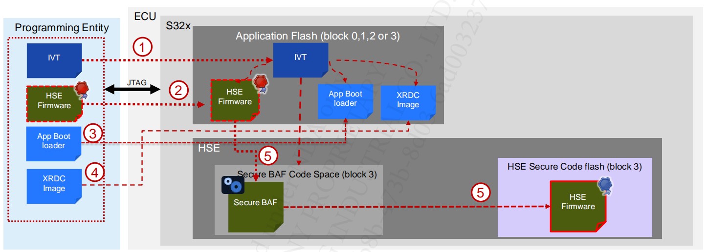
- The programming entity programs the images IVT in application flash block.
- The programming entity programs HSE FW Image in application flash block.
- The programming entity program app boot loader in application flash block.
- Programming entity programs XRDC image in application flash block & issues a reset
- Upon next boot HSE will decrypt, authenticate and program the HSE FW image in secure code area. It will boot the application and HSE FW.
The memory changes are shown in the following figure:
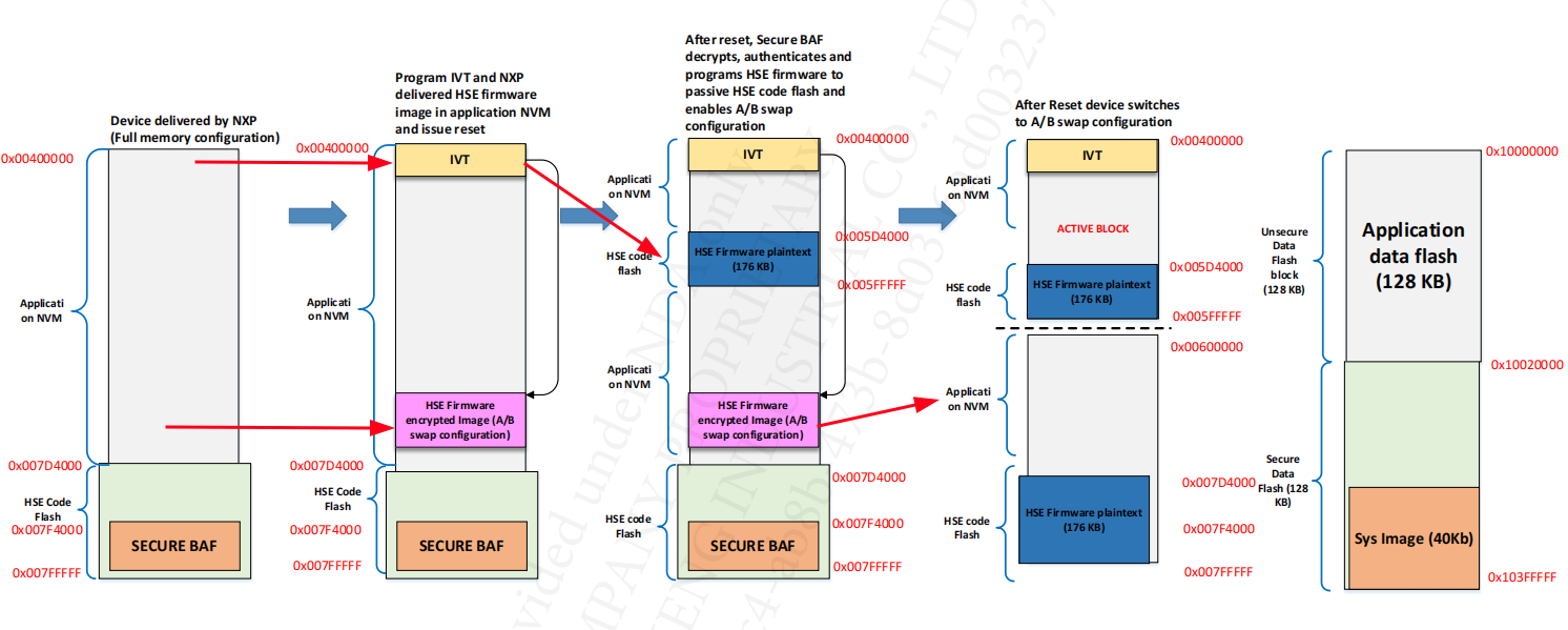
5.2 A/B Swap
After POR:
- The programming entity programs the images IVT in application flash block
- The programming entity programs A/B swap HSE FW Image in application flash block.
- The programming entity program app boot loader in application flash block
- Programming entity programs XRDC image in application flash block & issues a reset
- Upon next boot HSE will decrypt, authenticate and program the HSE FW image in secure code area. It will program A/B swap enable configuration, parameters and issue reset.
6. HSE config
The HSE firmware configuration is controlled and handled by the application through the different services available, under certain conditions, once the HSE firmware has been successfully installed:
- HSE attribute configuration (e.g. HSE Set Attribute service)
- Formatting the app key catalogs (HSE Key Catalog Format service)
- NVM key provisioning (generate/import/derive key services)
- Configuring Secure Memory Regions (HSE CR/SMR service)
- UTEST configuration done by application
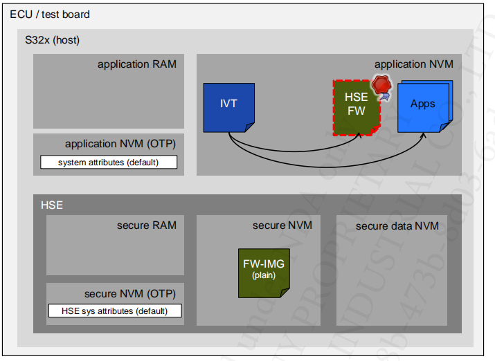
6.1 Default config
6.2 Config
- The Application formats the Application Key Catalog (NVM & RAM key catalogs)
- The Application configures the HSE: HSE Attribute Configuration, Key Provisioning, Secure Boot, etc.
- The Application configures the system configuration in UTEST
- Application signs the IVT & XRDC image using HSE service “Boot Data Sign” or offline using key derived from ADKP
- At reset, HSE load the SYS-IMG in its internal secure RAM
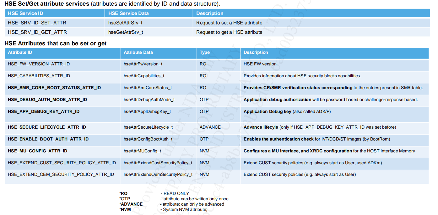
6.3 HSE ATTRIBUTE CONFIGURATION
6.4 Boot Sequence After Config
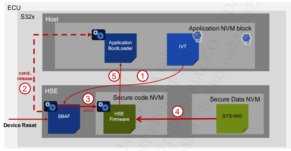
- SBAF reads the IVT.
- HSE Boot application incase non secure boot is desired.
- HSE starts the HSE Firmware.
- HSE firmware reads SYS-IMG (Keys, SMR and core reset table)
- HSE Firmware boots the app core configured in SMR)
7. Data Sync
7.1 Data synchronization with the HSE core
Data can be seen from the Figure 2 that the HSE service structure is passed between S32K3xx and HSE through MU, and HSE will execute the service according to the service ID and parameters (which can be values or addresses) in the structure.
D-Cache problem: For the data transferred between the dual cores, will be modified by at least one of the cores, when D-cache is enabled, the data synchronization issue will occur.
There are two solutions for the data synchronization:
- Users can choose to simply turn off the D-cache although will lose performance and will influence overall cache configurations.
- Put the data that may have data synchronization issue in a non-cacheable memory area while the D-Cache is enabling, taking affect only in an area of cacheable memory.
7.1.1 How to use global variables and temporary variables.
For the global value:
There are two types with initial value and without initial value:
- The global value with the initial value. Generally, the compiler puts the value with the initial value into the
.datasection. Refer to https://github.com/carloscn/blog/issues/5 - The global value without the initial value. it is placed into the section of
.bss.
Obviously, disabling the global D-Cache configuration is a worse method due to lose the global performance of the chip. As a result, we have to consider a method to control the data having synchronization issues populated into non-cacheable areas.
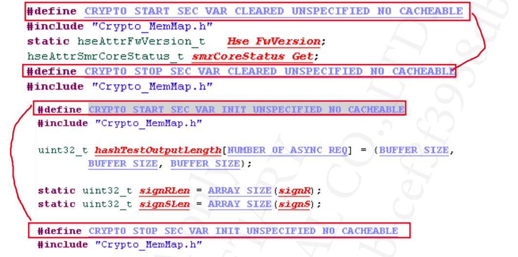
The S32K344 has defined a type of MemMap file to guide the compiler in formatting the memory. Through the precompiled directives(#prama section) defined in the MemMap file, assign the two type global variables to the non-cacheable data segment or non-cacheable bss segment as following figure.
For the temporary value:
Refer to https://github.com/carloscn/blog/issues/5 , the temporary value, being defined in one function, is placed into the .data or .text section after being compiled, deciding whether to with an initial value.
In the ARM Cortex-M7 design, as they are temporarily allocated on the stack, the M7 stack can only be placed in the non-cachable area.
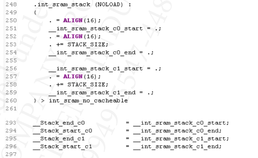
Unless by modifying the cache policy by the MPU module of the stack area to solve this problem.
If there is a memory management program, the user can also use a non-cacheble memory pool to allocate the space for the temporary variables.