blog
 blog copied to clipboard
[ls104x] Provisioning Guideline
ls104x Provisioning Guideline
!!!请严格按照本文步骤执行eFUSE的烧录(provisioning)。请每一步都要一个字一个字的读,不可以错过任何步骤,不可以越过任何的过程,即便你对一些过程已经熟悉。一个参数的错误都可能导致secure boot失败。
1. Provisioning
Provisioning分为两个阶段:
- 调试阶段:使用RCW来控制BootROM从mirror register读取SRKH;
- 生产阶段:RCW控制失效,BootROM强制从eFUSE读取SRKH;
调试阶段是给我们提供一个SRKH烧录错误的,我们只是把SRKH烧录到mirror registers,并没有真正的烧录到eFUSE。只有烧SFP_INGR register 之后,mirror register的值会被打到eFUSE上,此时eFUSE不可以被烧录,也就是进入到生产阶段。
1.1 调试阶段的Provisioning
烧录前提:需要一个非secure状态下编译的可以进入到uboot环境的firmware。
调试阶段的的Provisioning,需要烧录三个位置:
- OTPMK:最先烧录的,这个是烧录到真正的eFUSE,没有mirror机制。
- SRKH Mirror Register:这个是public key hash (SRK),烧录到mirror register
- OTPMK flags: 标志位
1.1.1 修改配置
1.1.1.1 准备input file
在这个路径下:

以下是完整的文件内容:
/*
 * Copyright 2018 NXP
 */

---------------------------------------------------
# Specify the platform. [Mandatory]
# Choose Platform - LS1/LS1043/LS1012/LS1046
PLATFORM=LS1043
---------------------------------------------------
# GPIO Pin to be set for raising POVDD [Optional]
POVDD_GPIO=230000020
---------------------------------------------------
# One time programmable master key flags in binary form.[Mandatory]
# 0000 -> Program default minimal OTPMK value
# 0001 -> Program random OTPMK value
# 0010 -> Program user supplied OTPMK value
# 0101 -> Program random OTPMK value with pre-programmed minimal value
# 0110 -> Program user supplied OTPMK value with pre-programmed minimal value
# 1xxx -> Don't blow OTPMK
OTPMK_FLAGS=0010
# One time programmable master key value.
# [Optional dependent on flags, Mandatory in case OTPMK_FLAGS="0010" or "0110"]
OTPMK_0=aa75f9a1
OTPMK_1=a57473d4
OTPMK_2=8d0603d5
OTPMK_3=3ad3e6d7
OTPMK_4=aa243543
OTPMK_5=c5cc1cb0
OTPMK_6=cbcc3904
OTPMK_7=aa13f3fc
---------------------------------------------------
# Super root key hash [Optional]
SRKH_0=1a897018
SRKH_1=d6e28f90
SRKH_2=038cd077
SRKH_3=4f4e1a1a
SRKH_4=dc045b54
SRKH_5=a14dc071
SRKH_6=ef414760
SRKH_7=8b4e04a6
---------------------------------------------------
# Specify OEM UIDs. [Optional]
# e.g OEM_UID_0=11111111
OEM_UID_0=
OEM_UID_1=
OEM_UID_2=
OEM_UID_3=
OEM_UID_4=
---------------------------------------------------
# Specify Debug challenge and response values. [Optional]
# e.g DCV_0=11111111
DCV_0=
DCV_1=
DRV_0=
DRV_1=
---------------------------------------------------
# Specify Debug Level in binary form. [Optional]
# 000 -> Wide open: Debug portals are enabled unconditionally.
# 001 -> Conditionally open via challenge response, without notification.
# 01x -> Conditionally open via challenge response, with notification.
# 1xx -> Closed. All debug portals are disabled.
DBG_LVL=
---------------------------------------------------
# System Configuration register bits in binary form [Optional]
# WP (OEM write protect)
# ITS (Intent to Secure)
# NSEC (Non secure)
# ZD (ZUC Disable)
# K0,K1,K2 (Key revocation bits)
# FR0 (Field return 0)
# FR1 (Field return 1)
WP=
ITS=
NSEC=
ZD=
K0=
K1=
K2=
FR0=
FR1=
---------------------------------------------------
# Specify the output fuse provisioning file name. (Default:fuse_scr.bin) [Optional]
OUTPUT_FUSE_FILENAME=fuse_scr.bin
---------------------------------------------------
我来解释一下,有几个注意的点:
POVDD_GPIO
The use of the trust architecture feature is dependent on programming fuses in the Security Fuse Processor (SFP). To program SFP fuses, the user is required to supply 1.8 V to the TA_PROG_SFP pin Power sequencing. TA_PROG_SFP should only be powered for the duration of the fuse programming cycle, with a per-device limit of six fuse programming cycles. At all other times, TA_PROG_SFP should be connected to GND.
In the AutoX hardware design, the
TA_PROG_SFPpin is connected to theUART2_RTS_Bpin. To pull theTA_PROG_SFPpin, theUART2_RTS_Bpin should be pulled high during the U-Boot boot stage.Refers the link https://www.nxp.com/webapp/Download?colCode=LS1043A (datasheet),
UART2_RTS_Bpin is shown in the following figure:In the hardware configuration,
UART2_RTS_Bis multiplexed withGPIO1_20.Referring to the documentation provided at Farnell's datasheet, the base addresses for GPIO can be obtained.
从上面的的引用可以推断出,GPIO1_20的地址是: MPC@0230000000 + 020 = MPC@0230000020
NXP在这里并没有给出POVDD_GPIO应该填写什么格式,通过实验直接230000020写即可。
OTPMK_FLAGS
标志位,上面文件给出了清晰的设置什么值对应什么功能的解说。我们这里选择:0010
OTPMK
OTPMK属于设备的master key,是在SoC安全应用派生keys的根key,也可以叫做device key。因此该key在随机数生成的时候必须符合标准。NXP提供了生成key的工具:
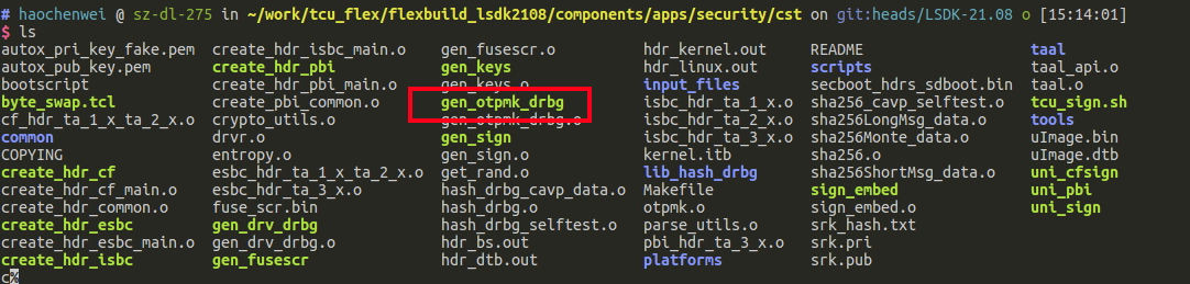
- Generate OTPMK.
-
cd cst -
./gen_otpmk_drbg -b 2
-
需要注意的是,在datasheet和user guide中并没有找到SNVS_HPSR_REG的寄存器地址。NXP的相关技术论坛中的技术支持对该问题也没有解答。
Input string not provided
Generating a random string
-------------------------------------------
* Hash_DRBG library invoked
* Seed being taken from /dev/random
-------------------------------------------
OTPMK[255:0] is:
aa75f9a1a57473d48d0603d53ad3e6d7aa243543c5cc1cb0cbcc3904aa13f3fc

 NAME    |     BITS     |    VALUE
_________|______________|____________
OTPMKR 0 | 255-224      |   aa75f9a1
OTPMKR 1 | 223-192      |   a57473d4
OTPMKR 2 | 191-160      |   8d0603d5
OTPMKR 3 | 159-128      |   3ad3e6d7
OTPMKR 4 | 127- 96      |   aa243543
OTPMKR 5 |  95- 64      |   c5cc1cb0
OTPMKR 6 |  63- 32      |   cbcc3904
OTPMKR 7 |  31-  0      |   aa13f3fc
我们分别把这个数据直接写到input file里面。
SRKH mirror register
SRKH是secure boot签名的public key的hash,由于我们的private key被封锁在了sign server上面。对应的公钥必须和私钥对应,因此需要使用改造后的cst,来完成SRKH的生成。
这部分直接可以在编译log里面找到:
SRK (Public Key) Hash:
1a897018d6e28f90038cd0774f4e1a1adc045b54a14dc071ef4147608b4e04a6
         SFP SRKHR0 = 1a897018
         SFP SRKHR1 = d6e28f90
         SFP SRKHR2 = 038cd077
         SFP SRKHR3 = 4f4e1a1a
         SFP SRKHR4 = dc045b54
         SFP SRKHR5 = a14dc071
         SFP SRKHR6 = ef414760
         SFP SRKHR7 = 8b4e04a6
同样把该值对应写到input file中。
ITS
这个位如果是调试阶段的话空着就可以了。写了之后整个eFUSE就被锁定了。因此在调试阶段不要写这个。
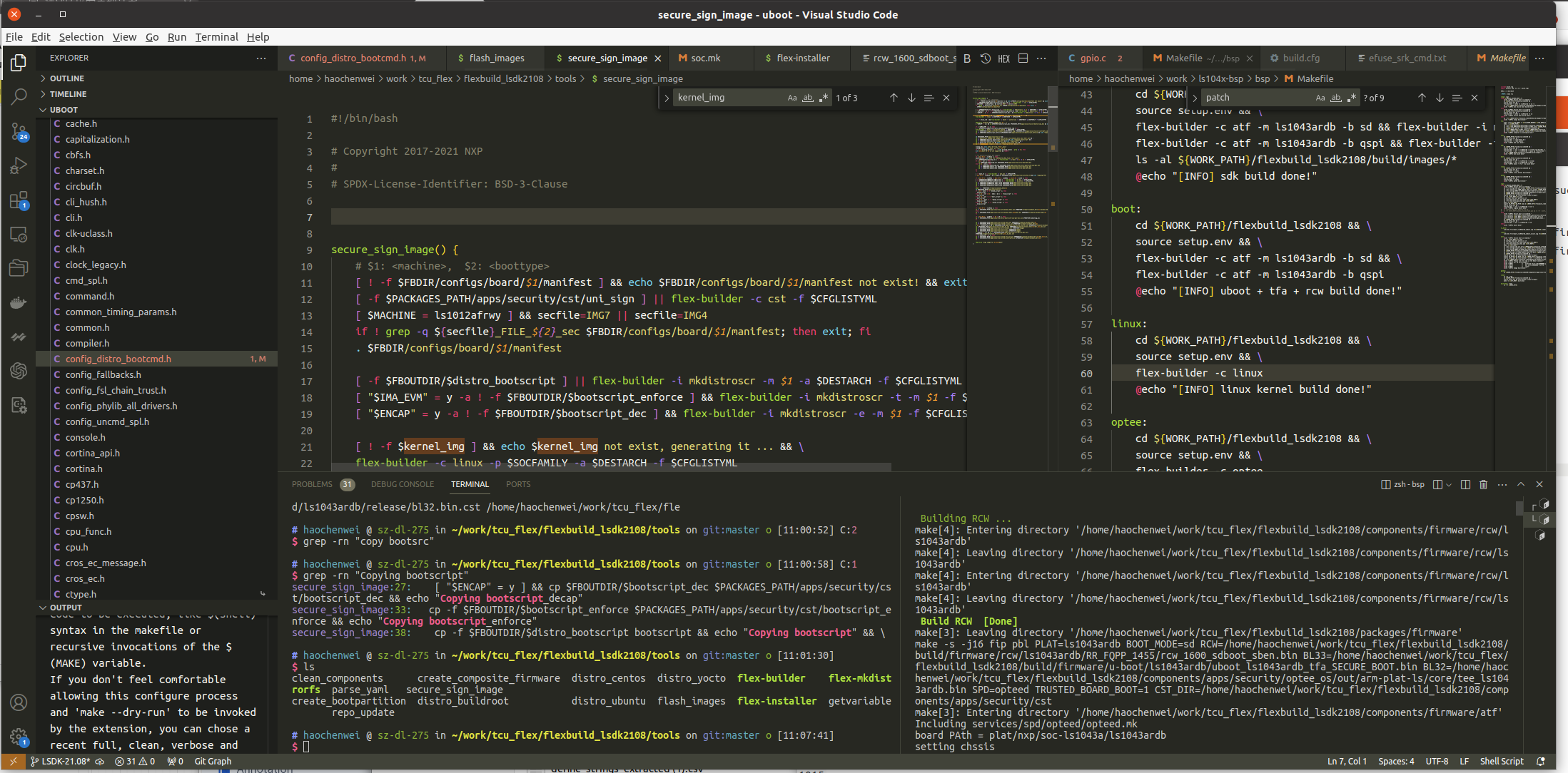
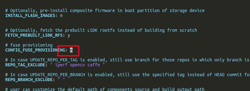
1.1.1.2 修改编译工程
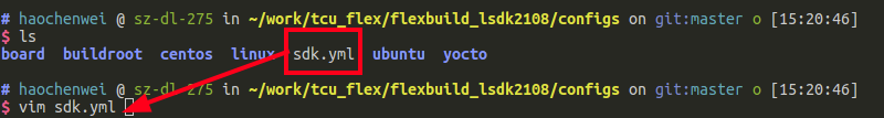
设定 CONFIG_FUSE_PROVISIONING=y 在 flexbuild_<version>/configs/sdk.yml
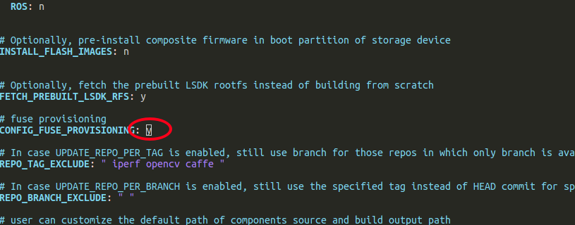
为y。
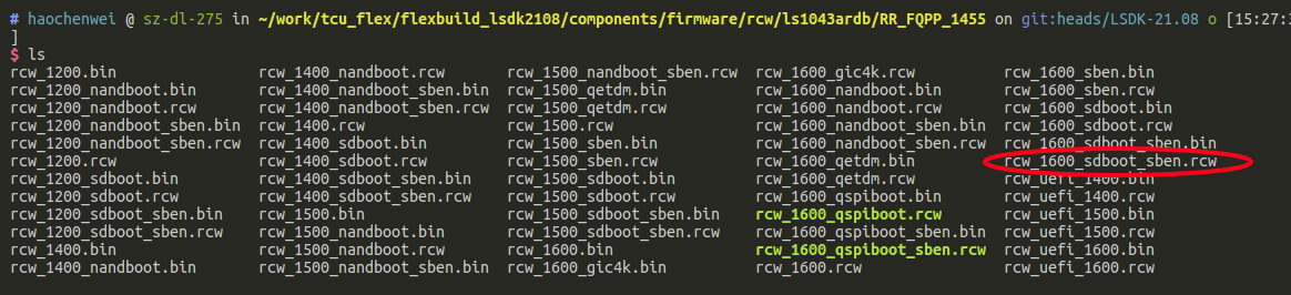
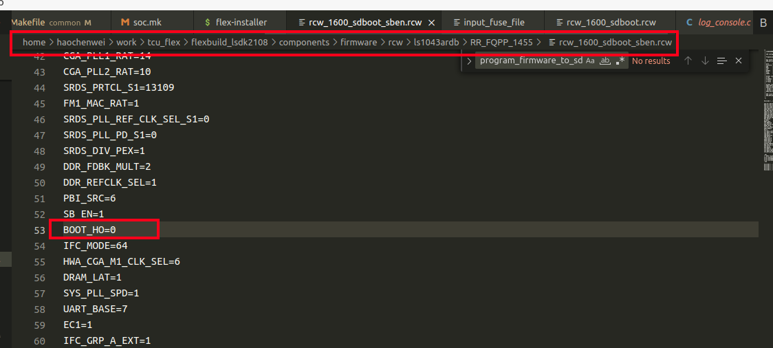
1.1.1.3 修改RCW文件
Secure boot模式的RCW文件在这里:
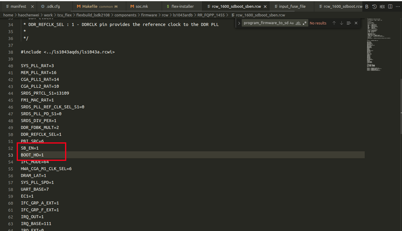
Provisioning时:SB_EN = 1 + BOOT_HO = 1
1.1.2 编译
先编译ATF:
flex-builder -c atf -m ls1043ardb -b sd
此时,会报错找不到load_img.h(这是flex-build的一个bug)
解决方案参考: https://community.nxp.com/t5/Layerscape/Build-ls1046a-fuse-provisioning-firmware-image-show-quot-load/m-p/1605060
$ flex-builder -c atf -m ls1046ardb -b sd
$ flex-builder -i mkfw -m ls1046ardb -b sd
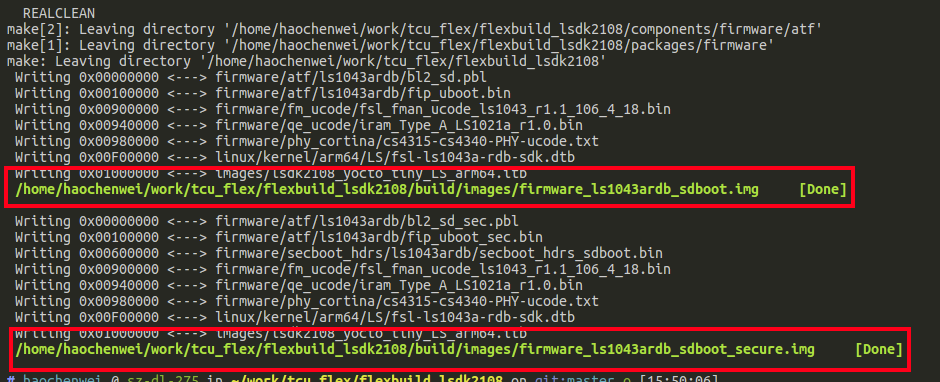
这个会生成一个非secure boot的固件和一个secure boot的固件。此时我们需要烧录firmware_ls1043ardb_sdboot_secure.img 。NXP把Provisioning的设备端的程序放在了ATF固件中。
我们此时最好来检查以下fuse.bin文件是否生成正确。我们打开这个文件:
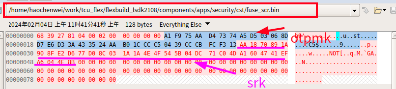
注意,这个值和我们当时在input file中的值大小端是相反的。
1.1.3 烧录
我们可以使用uboot的tftp或者存储到sd卡中通过fsload/ext4load来完成数据的加载。
我这里使用的存储到SD卡的ext4分区:
=> ext4load mmc 0:3 0xa0000000 prov.img
=> mmc write a0000000 8 1fff8
=> reset
此时,板子重启,provisioning在ATF启动阶段完成。
1.1.4 检查烧录情况
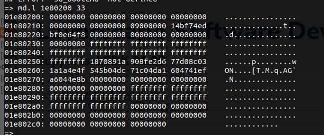
此时在uboot使用 md.l 1e80200 33 读取结果是这样就代表成功了。
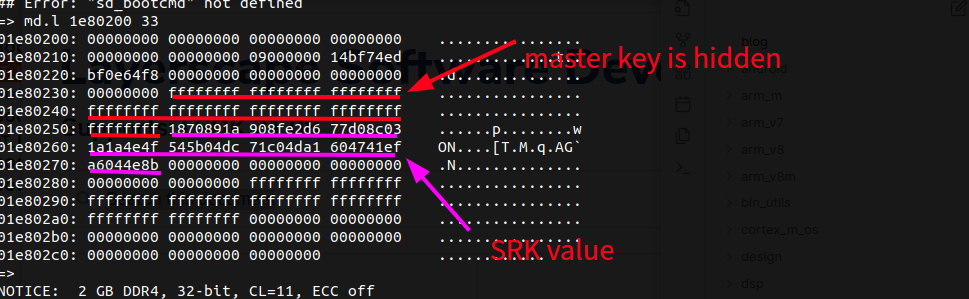
注意,此时由于ITS没有烧录,所以没有签名的编译正确的image也可以启动。当ITS被烧录之后,BootROM会强制校验hash。
1.1.1.4 编译
1.2 验证secure boot
我们需要对nxp的flex工程进行重新配置:
第一,sdk.yml中的provisioning要改为n
第二,RCW中的BOOT_HO改为0
第三,需要彻底清除掉atf的编译历史
flex-builder clean-firmware
第四,重新编译。
flex-builder -i mkfw -m ls1043ardb -b sd -s
最后重新烧录的sd卡,注意seek=4
sudo dd if=firmware_ls1043ardb_sdboot_secure.img of=/dev/sdb seek=4 bs=1k conv=fsync && sync
我们可以看到ATF的log:
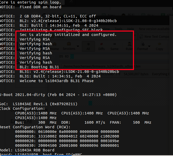
第一级引导ATF验证完毕。
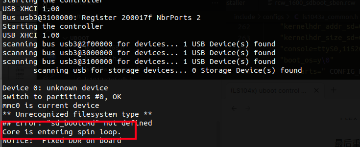
uboot会验证第二集引导:
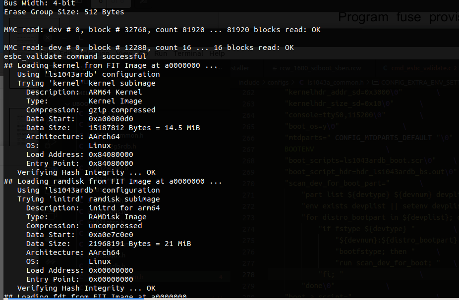
此时,TCU的整个secure boot开发阶段完成使能。
我们也可以用一个错误的例子,让kernel验证失败,会弹出: