ROBOTIS-OP3
 ROBOTIS-OP3 copied to clipboard
After over 5 months of working with my OP3 like-setup, I am getting an error right after the dynamixels flash.
Hi there, I originally posted back in December and Will Son helped me get up and running. Here: https://github.com/ROBOTIS-GIT/ROBOTIS-OP3/issues/105 I have built my own biped but have a Raspberry Pi4 (instead of the NUC) and an OpenCR. I have 26 DOF instead of 20. The first 20 are defined exactly like OP3 and I have downloaded and catkin_make all of OP3's packages. Over the last 5 months things have been fine and working. I have successfully run op3_bringup, as well as, self_test and was working on the action_editor when I ran into a full stop.
Right after the INFO message: Torque on DXLs! (and the dynamixels flash) I'm getting: [ERROR] [nnnn.nnnn]: Fail to control LED [[RxPacketError] Unknown error code!]
Then each error message for each joint gets displayed as well. [ERROR] [nnnn.nnnn]: JOINT[head_pan] does NOT respond!!
I was literally working on it over the last few days and suddenly, its dead in the water. I opened the biped up and physically checked all the wires and they are indeed attached. The U2D2 does some blinking and flashing, but is not blinking correctly. Of the 3 LEDs, the TxD and PWR are blinking but not the RxD. Does this sound familiar to anyone? Could this be a hardware issue, like the U2D2 not working properly after this amount of time? Is there any type of debugging that I could try to isolate where the problem really is? Could it have something to do with the FET not being actually turned on?
Its very strange, I did not change any code, was just adjusting offsets during the week as I tweaked the standup page, and was about to go through adding values for the extra 6 DXLs to some of the other pages when this occurred.
Any help or steering me in the correct direction would be very much appreciated. Thank you in advance, Smitty
Hi @Smitty-44 Glad to hear the progress you made during the last 5 months, and can't wait to see it working. The described problem looks unusual as Torque on packet works fine but LED doesn't. Checking whether U2D2 is alive with DYNAMIXEL Wizard 2.0 might help.
If the FET on the OpenCR doesn't work, the LED on DYNAMIXEL would not be turned on so the OpenCR looks good.
Hi Will Son, Thanks for replying. Yes, I thought the same thing, but wondered if it could be something else. I went ahead and ordered another U2D2. And over the last 5 months, I did a rebuild of the structure of the biped to add a usb_cam and to better house the internal electronics. It is coming along pretty well.
I do have another question if I may.
I know I talked about it some time ago, but I think I just simply didn't understand back then.
On the subject of the wifi hotspot, on the OP3, the wifi hotspot is the NUC, correct?
That's what has an address of 10.42.0.1, the NUC, correct?
I hope I am understanding this correctly.
Before I even started designing and building the parts for my biped, I had SSHed to my raspberry Pi using my desktop. And I was able to start processes like roscore, and the lidar, etc.
So, to setup the hotspot I would just have to work on the Pi for that.
And then alter accordingly on my desktop to be able to SSH in again.
I have instructions how to setup a Pi hotspot.
That is the last thing I haven't really setup yet.
My hope is to have this guy up and moving around later this year. And when I do, I will give you an update. He is kinda heavy though. Near the limits of the dynamixels. So, I am trying to be careful of that.
I want to thank you again for all your help. I really appreciate it. Cheers, Smitty
@Smitty-44 It is my pleasure to be able to give you a little help to resolve your issue on building OP3. As you correctly understood, the NUC is configured as a wifi hotspot so that external PC can connect to a specific IP address(10.42.0.1) assigned for the OP3 NUC.
However, the hotspot is not necessary if you are going to ssh into the Raspberry Pi through the external router. Web tools are providing features from a web browser that are already available from the ROS GUI so I'd say it is not a critical feature of running OP3.
I can't wait to see your project is completed! Will
Will Son, Thanks again for the quick responses and the info concerning the hotspot.
I received a new U2D2 and tried it connected to the upper 12 motors and using Wizard was able to see them all. So, I installed the new U2D2 but I got the same messages as before. I am afraid it might be the OpenCR board or something else, somehow. I was launching the action_editor as before, the LEDs on the motors flash, but then 5 messages: [ERROR] [nnnn.nnnn]: Torque on DXLs! [[RxPacketError] Unknown error code!] are displayed and then, [ERROR] [nnnn.nnnn]: Fail to control LED [[RxPacketError] Unknown error code!]
Do you know what I can check to see if the OpenCR board is the problem? Is it possible something on the OpenCR board is burnt out or damaged?
I do own a turtlebot3 burger. It does have an OpenCR in it, but of course, it has the turtlebot code loaded.
Cheers, Smitty
On Sun, Jul 11, 2021 at 10:13 PM Will Son @.***> wrote:
@Smitty-44 https://github.com/Smitty-44 It is my pleasure to be able to give you a little help to resolve your issue on building OP3. As you correctly understood, the NUC is configured as a wifi hotspot so that external PC can connect to a specific IP address(10.42.0.1) assigned for the OP3 NUC.
However, the hotspot is not necessary if you are going to ssh into the Raspberry Pi through the external router. Web tools are providing features from a web browser that are already available from the ROS GUI so I'd say it is not a critical feature of running OP3.
I can't wait to see your project is completed! Will
— You are receiving this because you were mentioned. Reply to this email directly, view it on GitHub https://github.com/ROBOTIS-GIT/ROBOTIS-OP3/issues/114#issuecomment-877919054, or unsubscribe https://github.com/notifications/unsubscribe-auth/ANVLKUYPY4B5BYECX5KBKS3TXJFVHANCNFSM477HT62Q .
@Smitty-44 If the OpenCR cannot provide sufficient power to all connected DYNAMIXEL, I think some of them may fail to respond. Supplying power directly from the battery to DYNAMIXEL could help reducing a burden of OpenCR as a power supply, but still it is weird that OpenCR cannot supply power to DYNAMIXEL under resting condition without a motion. Can you identify the DYNAMIXEL ID that do not respond?
Hi Will Son, I have both a battery and the power cord plugged into the OpenCR and it has worked fine for months. One day it was all working and the next, no movement from any of the 26 dynamixels at all. None of them respond at all. Is it possible something could have happened to the OpenCR, a burn out or something? How can I test the OpenCR to see if everything is working properly? Short of buying another OpenCR board, I was hoping there was something I could do before spending that kind of cash if the board is fine. Cheers, Smitty
On Thu, Jul 15, 2021 at 3:40 AM Will Son @.***> wrote:
@Smitty-44 https://github.com/Smitty-44 If the OpenCR cannot provide sufficient power to all connected DYNAMIXEL, I think some of them may fail to respond. Supplying power directly from the battery to DYNAMIXEL could help reducing a burden of OpenCR as a power supply, but still it is weird that OpenCR cannot supply power to DYNAMIXEL under resting condition without a motion. Can you identify the DYNAMIXEL ID that do not respond?
— You are receiving this because you were mentioned. Reply to this email directly, view it on GitHub https://github.com/ROBOTIS-GIT/ROBOTIS-OP3/issues/114#issuecomment-880470905, or unsubscribe https://github.com/notifications/unsubscribe-auth/ANVLKU3AJRGSHHPWNN3ANFTTX2GH3ANCNFSM477HT62Q .
Hi Smitty,
Oh, if all DYNAMIXEL isn't responding, it could be the fuse(10A, replaceable) on the back of the OpenCR. If the fuse gets blown up, none of SMPS or battery power is delivered to DYNAMIXEL.
A simple OpenCR test that can separate other possible factors would be connecting DYNAMIXEL to OpenCR and upload the DYNAMIXEL2Arduino > scan_dynamixel example.
If you see DYNAMIXEL blinking and detected in the Arduino terminal, you will be able to find out whether your OpenCR is good or not.
Hi Will Son, Yes, that's it. And I believe you are talking about this: Input Power Fuse 125V 10A LittleFuse 0453010 http://www.littelfuse.com/products/fuses/surface-mount-fuses/nano-2-fuses/453/453010.aspx
That makes perfect sense to me. Thank you again for your help! I will get on that and let you know how that pans out. Take care and Cheers, Smitty
On Fri, Jul 16, 2021 at 12:06 AM Will Son @.***> wrote:
Hi Smitty,
Oh, if all DYNAMIXEL isn't responding, it could be the fuse(10A, replaceable) on the back of the OpenCR. If the fuse gets blown up, none of SMPS or battery power is delivered to DYNAMIXEL.
A simple OpenCR test that can separate other possible factors would be connecting DYNAMIXEL to OpenCR and upload the DYNAMIXEL2Arduino > scan_dynamixel https://github.com/ROBOTIS-GIT/Dynamixel2Arduino/blob/master/examples/basic/scan_dynamixel/scan_dynamixel.ino example.
If you see DYNAMIXEL blinking and detected in the Arduino terminal, you will be able to find out whether your OpenCR is good or not.
— You are receiving this because you were mentioned. Reply to this email directly, view it on GitHub https://github.com/ROBOTIS-GIT/ROBOTIS-OP3/issues/114#issuecomment-881160304, or unsubscribe https://github.com/notifications/unsubscribe-auth/ANVLKU7G4SQY5LYG7BFWRWDTX6V2XANCNFSM477HT62Q .
Hi Will Son, Ok, here's what I did. I remembered, I have a turtlebot3 sitting in the corner. So, I took the fuse out of there and placed it in my biped. Still the same issue. So, I took out the entire turtlebot3 OpenCR board and compiled the op3 code using the Arduino IDE. And I switched the OpenCR boards, and still the same issue. So, if it isn't the U2D2 and it isn't the OpenCR board or its fuse, then the big question remains, why the sudden failure to power the dynamixels after working for months. I had previously, successfully, run the op3_bringup, many times over many weeks. I also had the gui run and moved the head. And I had successfully launched the self_test which also played the mp3 file, "self ready test mode". I have a speaker attached to the raspberry pi4 jack.
The problem occurred after I had successfully adjusted the offset file associated with the action_editor. I successfully played the standup page. It was ready to go. The next day, I was going to play other pages from the standup position when this occurred.
And the only thing I noticed which I know is not correct, is the U2D2 RxD led is not flashing at all. I changed out the TTL cable from the U2D2 and also the USB which is connected to the Pi4.
Sorry for this problem, but I am really stumped. Cheers, Smitty
On Fri, Jul 16, 2021 at 8:35 AM Jacob Smith @.***> wrote:
Hi Will Son, Yes, that's it. And I believe you are talking about this: Input Power Fuse 125V 10A LittleFuse 0453010 http://www.littelfuse.com/products/fuses/surface-mount-fuses/nano-2-fuses/453/453010.aspx
That makes perfect sense to me. Thank you again for your help! I will get on that and let you know how that pans out. Take care and Cheers, Smitty
On Fri, Jul 16, 2021 at 12:06 AM Will Son @.***> wrote:
Hi Smitty,
Oh, if all DYNAMIXEL isn't responding, it could be the fuse(10A, replaceable) on the back of the OpenCR. If the fuse gets blown up, none of SMPS or battery power is delivered to DYNAMIXEL.
A simple OpenCR test that can separate other possible factors would be connecting DYNAMIXEL to OpenCR and upload the DYNAMIXEL2Arduino > scan_dynamixel https://github.com/ROBOTIS-GIT/Dynamixel2Arduino/blob/master/examples/basic/scan_dynamixel/scan_dynamixel.ino example.
If you see DYNAMIXEL blinking and detected in the Arduino terminal, you will be able to find out whether your OpenCR is good or not.
— You are receiving this because you were mentioned. Reply to this email directly, view it on GitHub https://github.com/ROBOTIS-GIT/ROBOTIS-OP3/issues/114#issuecomment-881160304, or unsubscribe https://github.com/notifications/unsubscribe-auth/ANVLKU7G4SQY5LYG7BFWRWDTX6V2XANCNFSM477HT62Q .
@Smitty-44 Whoa, this is one of the most wicked issues that I had this year... Ok, let's go back to the very basic and see what we've missed.
- Do you see the led blink on every DYNAMIXEL when the op3_manager node is up and running?
- Since you have two working U2D2, can you connect on of them to your PC and detect all connected DYNAMIXEL from DYNAMIXEL Wizard 2.0? If they are detected, can you turn on the torque and update the Goal Position manually?
- ID 200 is assigned to the OpenCR and Wizard 2.0 will detect it as an unknown device like below.
 And should be able to read from the Control table using the Packet feature. The 1 byte Torque On flag is saved in the Address 24 and can be read as below.
 If Torque is turned on, the Parameter in the Status packet should be 0x01 instead of 0x00 as below.

Hi Will Son, For:
- During the bringup process, all the LEDs blink, but that is it. So, I just launched the op3_manager by itself. Same thing.
- So, this was really frustrating. I tried every way I could think of using the PC with the U2D2 and Wizard 2.0. Dynamixels never seen. I connected the PC to the U2D2, directly to a dynamixel powerhub (for the legs), while plugging the SMPS directly into the powerhub. The LEDs flash, but the Dynamixels were not detected with Wizard 2.0. I connected the PC to the U2D2 and a U2D2 power hub board directly to the motors, LEDs flashed when I turned on the powerboard switch, but that's it. Wizard 2.- doesn't see them. I even just connected the PC to the U2D2 to the OpenCR which had all the dynamixels connected to it. The SMPS was plugged into the OpenCR, I turned on the switch, LEDs flash, but the dynamixels not seen by Wizard 2.0. Everytime, I checked to make sure the PC and Wizard were looking at the same/correct COM port, usually COM3. Once it popped up as COM5. But I changed the settings in Wizard to correspond. It never saw the dynamixels. The connect button never lit up as well during all these attempts.
- this was a no go. Nothing was ever detected. I am completely dumbfounded now. The LEDs flashed, which I would take as a sign they are indeed getting power the moment they were plugged in or the appropriate switch was turned on, depending on each of the above setups. I tried various USB cables from the PC to the U2D2, nothing.
Is there a possibility that something is wrong with the SMPS? So, I have another one, and tried that one. No difference.
So, one last attempt...I started up* Dynamixel Wizard from RoboPlus*. And it found just the OpenCR board as id 200. I don't know what to make of all of this. Cheers, Smitty
On Sun, Jul 18, 2021 at 10:10 PM Will Son @.***> wrote:
@Smitty-44 https://github.com/Smitty-44 Whoa, this is one of the most wicked issues that I had this year... Ok, let's go back to the very basic and see what we've missed.
- Do you see the led blink on every DYNAMIXEL when the op3_manager node is up and running?
- Since you have two working U2D2, can you connect on of them to your PC and detect all connected DYNAMIXEL from DYNAMIXEL Wizard 2.0? If they are detected, can you turn on the torque and update the Goal Position manually?
- ID 200 is assigned to the OpenCR and Wizard 2.0 will detect it as an unknown device like below. [image: image] https://user-images.githubusercontent.com/26239359/126092090-221fb752-733b-446d-902e-8eb6eb7b3242.png And should be able to read from the Control table using the Packet feature. The 1 byte Torque On flag is saved in the Address 24 and can be read as below. [image: image] https://user-images.githubusercontent.com/26239359/126092615-af7d67fa-da10-4c4c-8c7b-9a110b1ba440.png If Torque is turned on, the Parameter in the Status packet should be 0x01 instead of 0x00 as below. [image: image] https://user-images.githubusercontent.com/26239359/126092729-8e52c932-d4b1-423a-93be-3c7d3d5781b8.png
— You are receiving this because you were mentioned. Reply to this email directly, view it on GitHub https://github.com/ROBOTIS-GIT/ROBOTIS-OP3/issues/114#issuecomment-882177556, or unsubscribe https://github.com/notifications/unsubscribe-auth/ANVLKU23B2ZQ7UQUWMIE5SDTYOCRRANCNFSM477HT62Q .
Will Son, I want you to know I found the source of the problem and fixed it. I am back up and running. I will explain the process in a reply tomorrow. It was not the U2D2 or the OpenCR. It was a damaged wire at the knee joint. Talk to you tomorrow. Cheers, Smitty
On Mon, Jul 19, 2021 at 12:46 PM Jacob Smith @.***> wrote:
Hi Will Son, For:
- During the bringup process, all the LEDs blink, but that is it. So, I just launched the op3_manager by itself. Same thing.
- So, this was really frustrating. I tried every way I could think of using the PC with the U2D2 and Wizard 2.0. Dynamixels never seen. I connected the PC to the U2D2, directly to a dynamixel powerhub (for the legs), while plugging the SMPS directly into the powerhub. The LEDs flash, but the Dynamixels were not detected with Wizard 2.0. I connected the PC to the U2D2 and a U2D2 power hub board directly to the motors, LEDs flashed when I turned on the powerboard switch, but that's it. Wizard 2.- doesn't see them. I even just connected the PC to the U2D2 to the OpenCR which had all the dynamixels connected to it. The SMPS was plugged into the OpenCR, I turned on the switch, LEDs flash, but the dynamixels not seen by Wizard 2.0. Everytime, I checked to make sure the PC and Wizard were looking at the same/correct COM port, usually COM3. Once it popped up as COM5. But I changed the settings in Wizard to correspond. It never saw the dynamixels. The connect button never lit up as well during all these attempts.
- this was a no go. Nothing was ever detected. I am completely dumbfounded now. The LEDs flashed, which I would take as a sign they are indeed getting power the moment they were plugged in or the appropriate switch was turned on, depending on each of the above setups. I tried various USB cables from the PC to the U2D2, nothing.
Is there a possibility that something is wrong with the SMPS? So, I have another one, and tried that one. No difference.
So, one last attempt...I started up* Dynamixel Wizard from RoboPlus*. And it found just the OpenCR board as id 200. I don't know what to make of all of this. Cheers, Smitty
On Sun, Jul 18, 2021 at 10:10 PM Will Son @.***> wrote:
@Smitty-44 https://github.com/Smitty-44 Whoa, this is one of the most wicked issues that I had this year... Ok, let's go back to the very basic and see what we've missed.
- Do you see the led blink on every DYNAMIXEL when the op3_manager node is up and running?
- Since you have two working U2D2, can you connect on of them to your PC and detect all connected DYNAMIXEL from DYNAMIXEL Wizard 2.0? If they are detected, can you turn on the torque and update the Goal Position manually?
- ID 200 is assigned to the OpenCR and Wizard 2.0 will detect it as an unknown device like below. [image: image] https://user-images.githubusercontent.com/26239359/126092090-221fb752-733b-446d-902e-8eb6eb7b3242.png And should be able to read from the Control table using the Packet feature. The 1 byte Torque On flag is saved in the Address 24 and can be read as below. [image: image] https://user-images.githubusercontent.com/26239359/126092615-af7d67fa-da10-4c4c-8c7b-9a110b1ba440.png If Torque is turned on, the Parameter in the Status packet should be 0x01 instead of 0x00 as below. [image: image] https://user-images.githubusercontent.com/26239359/126092729-8e52c932-d4b1-423a-93be-3c7d3d5781b8.png
— You are receiving this because you were mentioned. Reply to this email directly, view it on GitHub https://github.com/ROBOTIS-GIT/ROBOTIS-OP3/issues/114#issuecomment-882177556, or unsubscribe https://github.com/notifications/unsubscribe-auth/ANVLKU23B2ZQ7UQUWMIE5SDTYOCRRANCNFSM477HT62Q .
@Smitty-44 Sweet!! Glad to hear that you finally found what the problem is. That is weird though. Even if the cable is damaged, other DYNAMIXEL with good connection should be responding to Wizard 2.0. Thanks for the good news!
Hi Will Son, I decided to start at the beginning, like you inferred. I hooked up the U2D2 to the left elbow, l_el, and tried that with Dynamixel Wizard 2.0. It found it fine. So, I continued by adding the entire left arm, and Dyn Wiz 2.0 found all 5 dynamixels. Then I did the same for the right arm, which worked fine and then both arms and the 2 for the neck. Dyn Wiz 2.0 found all 12. I then connected the left leg and the 2 at the torso for my biped version and it found all 8. It came down to the right leg. I connected just the right leg and it did not find anything. So, I tried again with just the 2 left ankle dynamixels and it found both. Then, I connected it to the right knee and it didn't find anything. That isolated the problem to the right knee. When I disconnected the wires to the knee, I discovered one of the 3 individual wires had ripped out of the connector, showing bare wire. I replaced it with a new, longer wire and it worked. I connected all 26 to the U2D2 and Dyn Wiz 2.0 found all 26. I then reconnected everything back up and successfully launched action_editor. I am including a pic. [image: IMG_20210721_081326953.jpg] So, after finding this link: https://emanual.robotis.com/docs/en/dxl/x/xl430-w250/#connector-information I am concluding it is the #1 wire in the pinout in the housing which is the GND line. Please correct me if I am wrong. And that apparently makes all dynamixels appear to be not found. Does this make sense, Will Son? I hope I explained it correctly. If anyone runs into this same type of problem in the future, I hope this helps. Thanks again for all your help and patience. Cheers, Smitty
On Tue, Jul 20, 2021 at 9:30 PM Jacob Smith @.***> wrote:
Will Son, I want you to know I found the source of the problem and fixed it. I am back up and running. I will explain the process in a reply tomorrow. It was not the U2D2 or the OpenCR. It was a damaged wire at the knee joint. Talk to you tomorrow. Cheers, Smitty
On Mon, Jul 19, 2021 at 12:46 PM Jacob Smith @.***> wrote:
Hi Will Son, For:
- During the bringup process, all the LEDs blink, but that is it. So, I just launched the op3_manager by itself. Same thing.
- So, this was really frustrating. I tried every way I could think of using the PC with the U2D2 and Wizard 2.0. Dynamixels never seen. I connected the PC to the U2D2, directly to a dynamixel powerhub (for the legs), while plugging the SMPS directly into the powerhub. The LEDs flash, but the Dynamixels were not detected with Wizard 2.0. I connected the PC to the U2D2 and a U2D2 power hub board directly to the motors, LEDs flashed when I turned on the powerboard switch, but that's it. Wizard 2.- doesn't see them. I even just connected the PC to the U2D2 to the OpenCR which had all the dynamixels connected to it. The SMPS was plugged into the OpenCR, I turned on the switch, LEDs flash, but the dynamixels not seen by Wizard 2.0. Everytime, I checked to make sure the PC and Wizard were looking at the same/correct COM port, usually COM3. Once it popped up as COM5. But I changed the settings in Wizard to correspond. It never saw the dynamixels. The connect button never lit up as well during all these attempts.
- this was a no go. Nothing was ever detected. I am completely dumbfounded now. The LEDs flashed, which I would take as a sign they are indeed getting power the moment they were plugged in or the appropriate switch was turned on, depending on each of the above setups. I tried various USB cables from the PC to the U2D2, nothing.
Is there a possibility that something is wrong with the SMPS? So, I have another one, and tried that one. No difference.
So, one last attempt...I started up* Dynamixel Wizard from RoboPlus*. And it found just the OpenCR board as id 200. I don't know what to make of all of this. Cheers, Smitty
On Sun, Jul 18, 2021 at 10:10 PM Will Son @.***> wrote:
@Smitty-44 https://github.com/Smitty-44 Whoa, this is one of the most wicked issues that I had this year... Ok, let's go back to the very basic and see what we've missed.
- Do you see the led blink on every DYNAMIXEL when the op3_manager node is up and running?
- Since you have two working U2D2, can you connect on of them to your PC and detect all connected DYNAMIXEL from DYNAMIXEL Wizard 2.0? If they are detected, can you turn on the torque and update the Goal Position manually?
- ID 200 is assigned to the OpenCR and Wizard 2.0 will detect it as an unknown device like below. [image: image] https://user-images.githubusercontent.com/26239359/126092090-221fb752-733b-446d-902e-8eb6eb7b3242.png And should be able to read from the Control table using the Packet feature. The 1 byte Torque On flag is saved in the Address 24 and can be read as below. [image: image] https://user-images.githubusercontent.com/26239359/126092615-af7d67fa-da10-4c4c-8c7b-9a110b1ba440.png If Torque is turned on, the Parameter in the Status packet should be 0x01 instead of 0x00 as below. [image: image] https://user-images.githubusercontent.com/26239359/126092729-8e52c932-d4b1-423a-93be-3c7d3d5781b8.png
— You are receiving this because you were mentioned. Reply to this email directly, view it on GitHub https://github.com/ROBOTIS-GIT/ROBOTIS-OP3/issues/114#issuecomment-882177556, or unsubscribe https://github.com/notifications/unsubscribe-auth/ANVLKU23B2ZQ7UQUWMIE5SDTYOCRRANCNFSM477HT62Q .
@Smitty-44 Thank you very much for the detailed description about the way you identified the problem. The GND is a very important wire because it works as a reference voltage(0 V) for communication as well as providing current circulation for connected modules. I wish the rest of development goes well without any hick ups!
Will
Hi Will, Fantastic! I'm glad my wire problem and fix helped someone.
So, I am at the stage where I have modified the actions with the action_editor and now want to run them with sound. Of course, I saw that requires using the 4 buttons...which I do not have yet. I saw the pdf schematic drawings of the small boards like OP3_GPIO Board. I already have a speaker added to the Pi which can default through the jack connection. And I have played the "self test ready mode" already, through that speaker. I know I need to create those boards/wiring on my own since those are not sold separately, and I have an "idea" on how to do it, just not the expertise. I am new to wiring from a schematic (I've done numerous easy ones), but I gave it a try. I have a couple of questions. Can I test any of these just connecting them to the OpenCR or do I need to power up everything? I ask this because I am a little anxious I may short something out due to any incorrect wiring of mine. Is there any other guidance you can give to aid me in not fudging this all up?
I have the appropriate 12 wires connected out from the OpenCR GPIO pins to a large breadboard for prototyping. I have probably over wired the 4 buttons. Hopefully you can track the wiring in the included snapshot and point out any obvious mistakes. You can see the power (red) and GND (black) wires on the left coming in. Then the RGB LED, and the 3 LEDs, then the 4 buttons, with the first blue button being the SW_MODE, then SW_START, SW_USER, and DXL_PWR_RESET in order.

I tried to follow 7.3.3. Boards from the emanual: https://github.com/ROBOTIS-GIT/ROBOTIS-OP-Series-Data/blob/master/ROBOTIS-OP3/Hardware/Electronics/Boards/OP3_GPIO_Board_170213.pdf
As always, thank you for your help. And if I should contact someone else at Robotis, please let me know that as well. Cheers, Smitty
Hi @Smitty-44 Glad that you are getting one step closer to the final touch. Though it is difficult to review your design, as long as you have correctly implemented the circuit based on the provided PCB schematics, you should be good to go. The OP3 buttons will be connected to the digital pins (pulled up high when not pressed) of the OpenCR GPIO Pin 7~10 (MODE, START, USER, RESET respectively).
The RGB LED for the front and other three R / G / B LEDs for the back near the buttons are also connected to the OpenCR GPIO, and powered by the VCC_3.3V from the GPIO pin 1 of the OpenCR.
I'd recommend separately check the input and output with an external power source (if you have 3.3V power supply) before connecting to OpenCR.
Just make sure that the Button outputs are not directly connected to the power source (such as 3.3V or 5V) because the other side of the button is fixed to the ground and as soon as you press the button, the circuit will be shorted between input(ground) and output.
LEDs are relatively safer than buttons as they are protected with diodes and resistors, but pay attention when connecting to the correct GPIO pins.
Thanks!
Hi Will Son, That's my problem. I can look at simple PCB schematics, but these two pdfs confuse me. I see those two molex connectors, plus whatever is being used for the speaker. I have a speaker connected to the Pi jack, and is the default. Will that work for the modes? Must I have the Speaker Amp board and another speaker? Right now, when I bring up self ready test, the mp3 file plays thru my Pi speaker. I also see a number of capacitors out there. Are there any other hints you can throw my way? I usually can figure things out with actual pics. I wired the 12 GPIO pins, (1 and 2 and the other 10) as in the "OP3_GPIO Board" pdf, but right now I do not have the 3 capacitors wired. Should the 3 separate LEDs be connected to GND? I'm not sure I see that. And I'm confused how it all links together. Maybe I have it wired correctly, but I am hesitant to connect to my OpenCR and my biped.
Is there a way for me, from the command line, to just run whatever Mode, or Start, or Reset? The only other information I found out there (through google translate) was someone else inquiring about the boards and connections and I think someone sent them an email and they instantly understood. Thank you for answering all my questions, all the time. I really appreciate it. Cheers, Smitty I added a photo for whatever it's worth. When I turn on the OpenCR, all the LEDs light up. [image: IMG_20210816_141658295_HDR.jpg]
On Tue, Aug 10, 2021 at 10:11 PM Will Son @.***> wrote:
Hi @Smitty-44 https://github.com/Smitty-44 Glad that you are getting one step closer to the final touch. Though it is difficult to review your design, as long as you have correctly implemented the circuit based on the provided PCB schematics, the OP3 buttons will be powered by the OpenCR GPIO Pin 7~10 (MODE, START, USER, RESET respectively).
The RGB LED for the front and other three R / G / B LEDs for the back near the buttons are also connected to the OpenCR GPIO, and powered by the VCC_3.3V from the GPIO pin 1 of the OpenCR.
I'd recommend separately check the input and output with an external power source (if you have 3.3V power supply) before connecting to OpenCR.
Just make sure that the Button outputs are not directly connected to the power source (such as 3.3V or 5V) because the other side of the button is fixed to the ground and as soon as you press the button, the circuit will be shorted between input(ground) and output.
LEDs are relatively safer than buttons as they are protected with diodes and resistors, but pay attention when connecting to the correct GPIO pins.
Thanks!
— You are receiving this because you were mentioned. Reply to this email directly, view it on GitHub https://github.com/ROBOTIS-GIT/ROBOTIS-OP3/issues/114#issuecomment-896444984, or unsubscribe https://github.com/notifications/unsubscribe-auth/ANVLKU7RIZYWBITNJNAYEQDT4HL57ANCNFSM477HT62Q . Triage notifications on the go with GitHub Mobile for iOS https://apps.apple.com/app/apple-store/id1477376905?ct=notification-email&mt=8&pt=524675 or Android https://play.google.com/store/apps/details?id=com.github.android&utm_campaign=notification-email .
As long as the pi speaker works, you don't need additional speaker amp to amplify the sound.
The LED should be carefully connected. The longer pin is Anode(+), and the other is Cathode(-) as below.
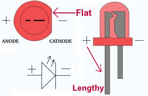
image source: http://www.zpag.net/Electroniques/Diode/led_find__anode_and_cathode.html
The Anode pins should be connected to the 3.3V pin of the OpenCR while Cathodes should be connected to GPIO Pin 4(Red), Pin 5(Green), Pin 6(Blue) respectively.
In this way, the MCU can drop the LED_Signal_IN_# pins to LOW(0V) to turn the LED on while turning them off with HIGH(3.3V) output. 330ohm resistors are important because they limit the amount of current flows through the LED.
I haven't tried it before, but there are subscribers for getting demo mode and button status https://github.com/ROBOTIS-GIT/ROBOTIS-OP3-Demo/blob/master/op3_demo/src/demo_node.cpp#L77-L78 You may publish necessary string such as "soccer", "vision", "action" and then "start" to begin the demo.
I'm sorry but I can't see the picture. When attaching pictures in the email reply, it doesn't seem to be included in the reply on Github.
Hi Will Son, Thank you very much for the response. Definitely answers most of questions. Yes, I can just use my speaker and yes, I can send commands for the modes, etc., from the command line. I understand about the anode and cathode for the LEDs, but I checked my wiring again. Also, I have resistors for them as well and they are 330ohm. I am replying through github this time, so hopefully you will see my 2 pics even though they maybe hard to see. If you see anything glaringly wrong, please shout out. I know it is hard to see.
First one, is the current breadboard wiring which will need replaced by a PCB or two.
It is a U2D2 connected to an OpenCR which has the OP3 firmware loaded.
It shows the 12 wires coming out of the OpenCR GPIOs, and running out to breadboards.
The small yellow breadboard has the 1 (+), and 2 (-) wires from the OpenCR, included with the 3 capacitors as indicated by the schematics, and then connects to the large breadboard's + and - .
The other 10 GPIO wires, 3 for the LED RGB, 3 more for the separate LEDs, and 4 for the buttons.

Second one, is the U2D2 plugged into the desktop, and the OpenCR with power applied.
The LED RGB lights up, the others do not, the U2D2 does not have data being sent at that moment, I took the pic, and then I quickly turn the power off and disconnect the U2D2 from the desktop.

These pictures are just in case you see something terribly wrong. At this point I will continue working on going from here to creating PCBs. And I will experiment with trying to execute from a terminal. Thank you so much for your patience, understanding and straight forward explanations. As always, Cheers, Smitty
Hi @Smitty-44 Sorry I didn't have enough time to take a closer look this week. I'll review on this next week and get back to you if it is okay with you. Thanks!