ATtiny13-ContinuityTester
 ATtiny13-ContinuityTester copied to clipboard
Simple Continuity Tester
Continuity Tester based on ATtiny13A
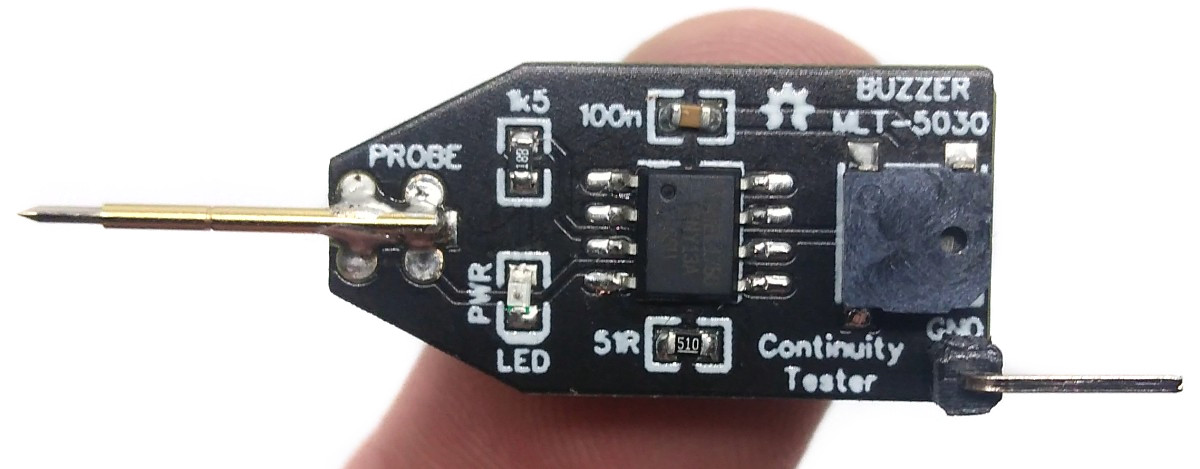
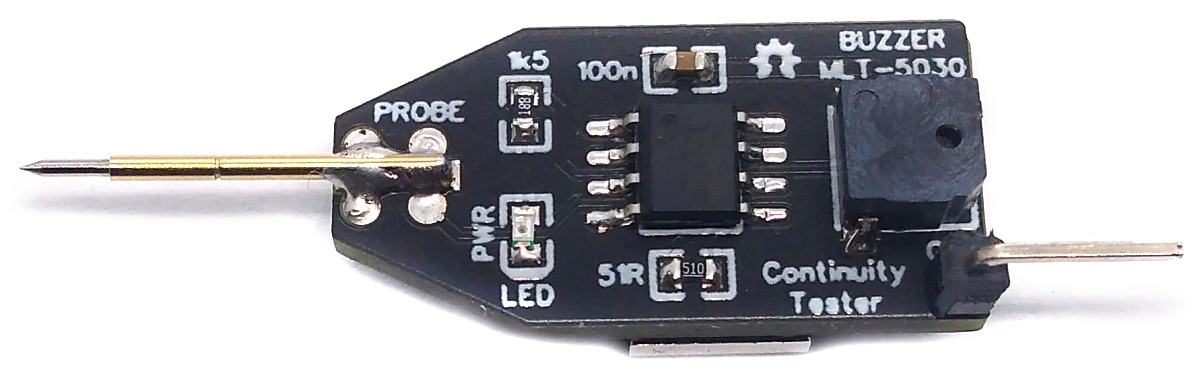
The simple yet effective Continuity Tester is just a conversion of the original one by David Johnson-Davies from the ATtiny85 to the ATtiny13A. It is designed to check circuit wiring and PCB tracks.
- Design Files (EasyEDA): https://easyeda.com/wagiminator/attiny13-continuity-tester
Hardware
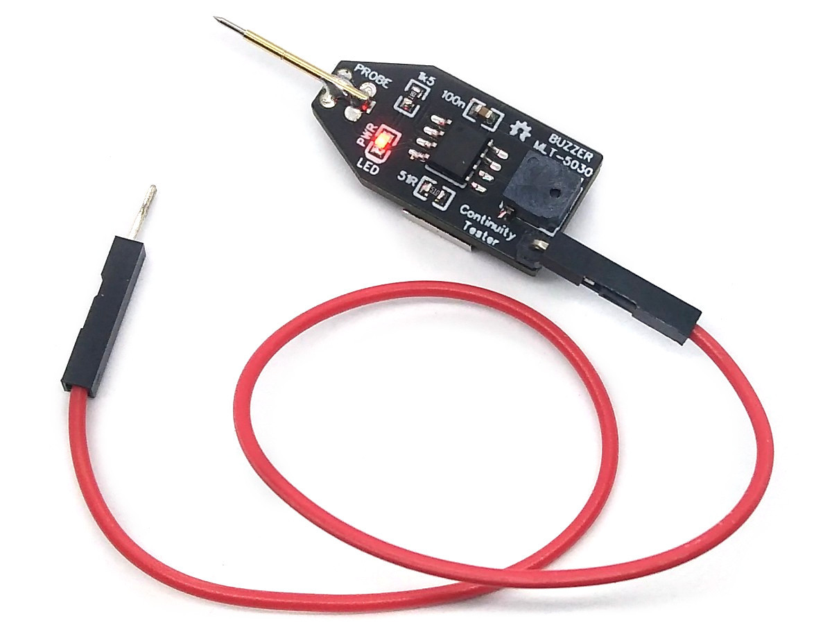
The basic wiring is shown below:

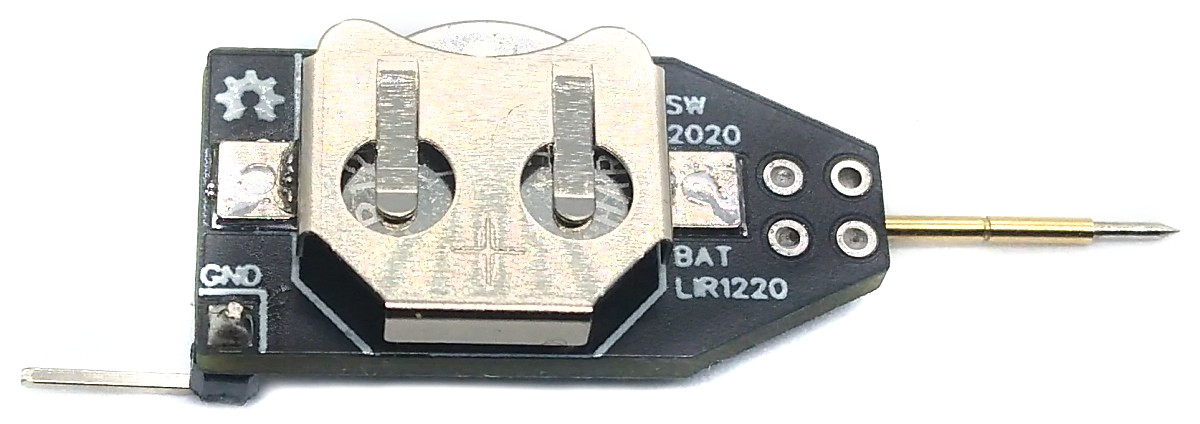
Connect one end of a wire to the GND terminal and use the other end together with the pogo pin to check the continuity of wires and traces. The device is powered by a 1220 coin cell battery. Please remember that only the rechargeable LIR1220 Li-Ion batteries work. The "normal" CR1220s don't deliver enough power for the buzzer.
Software
Implementation
The code is using the internal analog comparator of the ATtiny. By using the internal pullup resistors on both inputs of the comparator and by using a 51 Ohm pulldown resistor to form a voltage divider on the positive input, the comparator output becomes high if the resistance between both probes is less then 51 Ohms. This indicates a continuity between the probes and the buzzer will be turned on. For a more precise explanation refer to David's project. Timer0 is set to CTC mode with a TOP value of 127 and no prescaler. At a clockspeed of 128 kHz it fires every millisecond the compare match A interrupt which is used as a simple millis counter. In addition the compare match interrupt B can be activated to toggle the buzzer pin at a frequency of 1000 Hz, which creates a "beep". If no continuity between the probes is detected for 10 seconds, the ATtiny is put into sleep, consuming almost no power. The device can be reactivated by holding the two probes together. The LED lights up when the device is activated and goes out when the ATtiny is asleep. The code needs only 280 bytes of flash if compiled with LTO.
// Libraries
#include <avr/io.h>                             // for GPIO
#include <avr/sleep.h>                          // for sleep mode
#include <avr/interrupt.h>                      // for interrupts

// Pin definitions
#define REF       PB0                           // reference pin
#define PROBE     PB1                           // pin connected to probe
#define LED       PB2                           // pin connected to LED
#define EMPTY     PB3                           // unused pin
#define BUZZER    PB4                           // pin connected to buzzer

// Firmware parameters
#define TIMEOUT   10000                         // sleep timer in ms
#define DEBOUNCE  50                            // buzzer debounce time in ms

// Global variables
volatile uint16_t tmillis = 0;                  // counts milliseconds

// Main function
int main(void) {
  set_sleep_mode(SLEEP_MODE_PWR_DOWN);          // set sleep mode to power down
  PRR    = (1<<PRADC);                          // shut down ADC to save power
  DIDR0  = (1<<REF) | (1<<EMPTY);               // disable digital input on REF and EMPTY
  DDRB   = (1<<LED) | (1<<BUZZER);              // LED and BUZZER pin as output
  PORTB  = (1<<LED) | (1<<REF) | (1<<PROBE);    // LED on, internal pullups for REF and PROBE
  OCR0A  = 127;                                 // TOP value for timer0
  OCR0B  = 63;                                  // for generating 1000Hz buzzer tone
  TCCR0A = (1<<WGM01);                          // set timer0 CTC mode
  TCCR0B = (1<<CS00);                           // start timer with no prescaler
  TIMSK0 = (1<<OCIE0A);                         // enable output compare match A interrupt
  PCMSK  = (1<<PROBE);                          // enable interrupt on PROBE pin
  sei();                                        // enable global interrupts

  // Loop
  while(1) {
    if(ACSR & (1<<ACO)) {                       // continuity detected?
      tmillis = 0;                              // reset millis counter
      TIMSK0 |= (1<<OCIE0B);                    // buzzer on
    } else if(tmillis > DEBOUNCE)               // no continuity detected?
      TIMSK0 &= ~(1<<OCIE0B);                   // buzzer off after debounce time

    if(tmillis > TIMEOUT) {                     // go to sleep?
      PORTB &= ~(1<<LED);                       // LED off
      PORTB &= ~(1<<REF);                       // turn off pullup to save power
      GIMSK  =  (1<<PCIE);                      // enable pin change interrupts
      sleep_mode();                             // go to sleep, wake up by pin change
      GIMSK  = 0;                               // disable pin change interrupts
      PORTB |=  (1<<REF);                       // turn on pullup on REF pin
      PORTB |=  (1<<LED);                       // LED on
    }
  }
}

// Pin change interrupt service routine - resets millis
ISR(PCINT0_vect) {
  tmillis = 0;                                  // reset millis counter
}

// Timer/counter compare match A interrupt service routine (every millisecond)
ISR(TIM0_COMPA_vect) {
  PORTB &= ~(1<<BUZZER);                        // BUZZER pin LOW
  tmillis++;                                    // increase millis counter
}

// Timer/counter compare match B interrupt service routine (enabled if buzzer has to beep)
ISR(TIM0_COMPB_vect) {
  PORTB |= (1<<BUZZER);                         // BUZZER pin HIGH
}
Compiling and Uploading
Since there is no ICSP header on the board, you have to program the ATtiny either before soldering using an SOP adapter, or after soldering using an EEPROM clip. The AVR Programmer Adapter can help with this.
If using the Arduino IDE
- Make sure you have installed MicroCore.
- Go to Tools -> Board -> MicroCore and select ATtiny13.
- Go to Tools and choose the following board options:
- Clock: 128 kHz internal osc.
- BOD: BOD disabled
- Timing: Micros disabled
- Connect your programmer to your PC and to the ATtiny.
- Go to Tools -> Programmer and select your ISP programmer (e.g. USBasp).
- Go to Tools -> Burn Bootloader to burn the fuses.
- Open ContinuityTester.ino and click Upload.
If using the precompiled hex-file
- Make sure you have installed avrdude.
- Connect your programmer to your PC and to the ATtiny.
- Open a terminal.
- Navigate to the folder with the hex-file.
- Execute the following command (if necessary replace "usbasp" with the programmer you use):
avrdude -c usbasp -p t13 -U lfuse:w:0x3b:m -U hfuse:w:0xff:m -U flash:w:continuitytester.hex
If using the makefile (Linux/Mac)
- Make sure you have installed avr-gcc toolchain and avrdude.
- Connect your programmer to your PC and to the ATtiny.
- Open a terminal.
- Navigate to the folder with the makefile and sketch.
- Run
PROGRMR=usbasp make installto compile, burn the fuses and upload the firmware (change PROGRMR accordingly).
References, Links and Notes
License

This work is licensed under Creative Commons Attribution-ShareAlike 3.0 Unported License. (http://creativecommons.org/licenses/by-sa/3.0/)