4-pin No Display/No Control
Hello, I found this project a few weeks ago and by now have assembled the 4-Wire version of a #54123 (Eggplant) Miami (Is a few years old). Which is owned by my father.
(I have a 6 Pin 2021 Cube Shape Helsinki which i also attempt to modify, which also doesn't work, but i will open another issue if i can't figure it out in the next few days [at least it shows temperature, but no control])
So much for the introduction.
Specifications: Lay-Z Miami Pump version #54123 (AirJet, no HydroJet) Used Code 4 wire, master branch (latest to date) Used the: #define NO54123 in model.h commented out the #define NO54138 Web Panel - Working (I translated it to german, but retried everything from scratch today, so im back to original)
ESP is starting up fine even when plugged in.
I'm not sure, could the issue be a defect in the LLC? I read some people had issues and destroyed it while soldering, so i really tried to watch the temperature and let it cool down. How would i measure if it works correctly?
Or any idea how to start the troubleshooting process?
If i can somehow contribute to the project I'm happy to help. (And yes, i took the pump into my apartment, because i could test control with bubbles for example)
Pictures below:
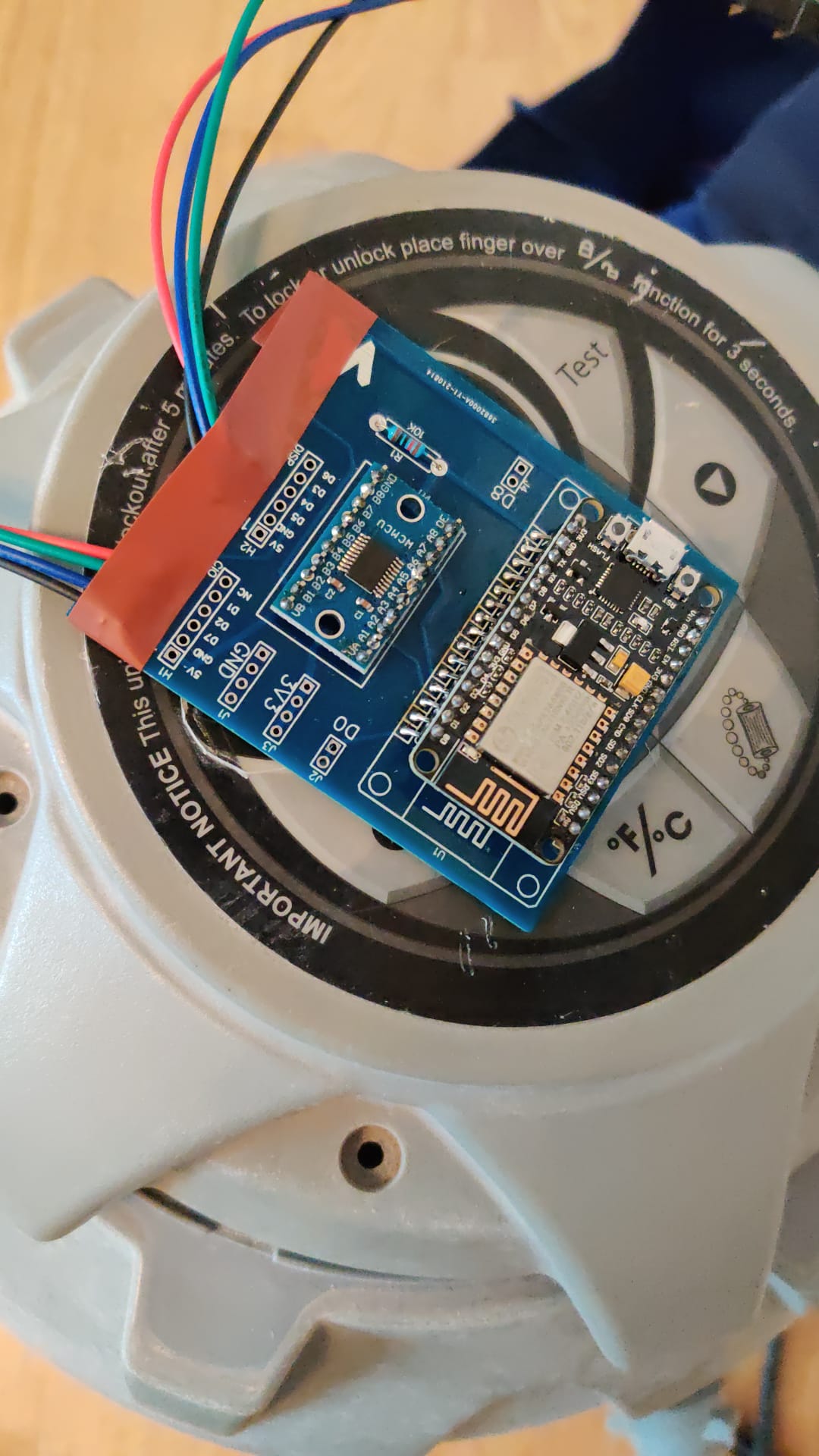

Hi, I'd start by measuring 0 Ohms between the two connectors' power pins. Gnd-gnd. 5v-5v. Then check between each data pin in the connectors and the corresponding pin on the LLC 5v side. Also make sure you don't have shorts between adjacent pins
So thanks for the quick response by the way.
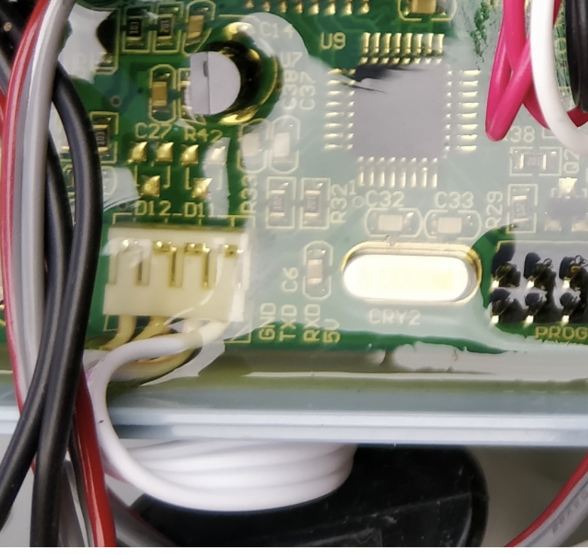
After measuring everything trough and checking the pump with a flashlight again i noticed that the Pins are: 5V, RX, TX, GND in that order.
So my soldering 5V,GND,... couldn't work in the first place. (And im lucky i didn't fry anything) Should have double checked, as it is clearly stated in the instructions.
Luckily the connections on the board itself seem fine.
I will resolder the connection pins and report back afterwards. Might take 1-2 days until i got time for that.
h2owasser, did you manage to connect Miami?
I have a similar version of Miami ( the same #54123), the same 4 wires but with a different cover. And I have the same problem as you when connecting. But I have not yet even managed to determine which of the RX wires, which 5 V, and which TX. When measuring with a multimeter with a connected screen on all 3 wires, I have 5v. What am I doing wrong?
Sorry for the late reply. Night Shift is taking it's toll in my productivity there. I couldn't continue on the testing on my side (and i do not have time until around the 20th) so i can't report back properly, sorry.
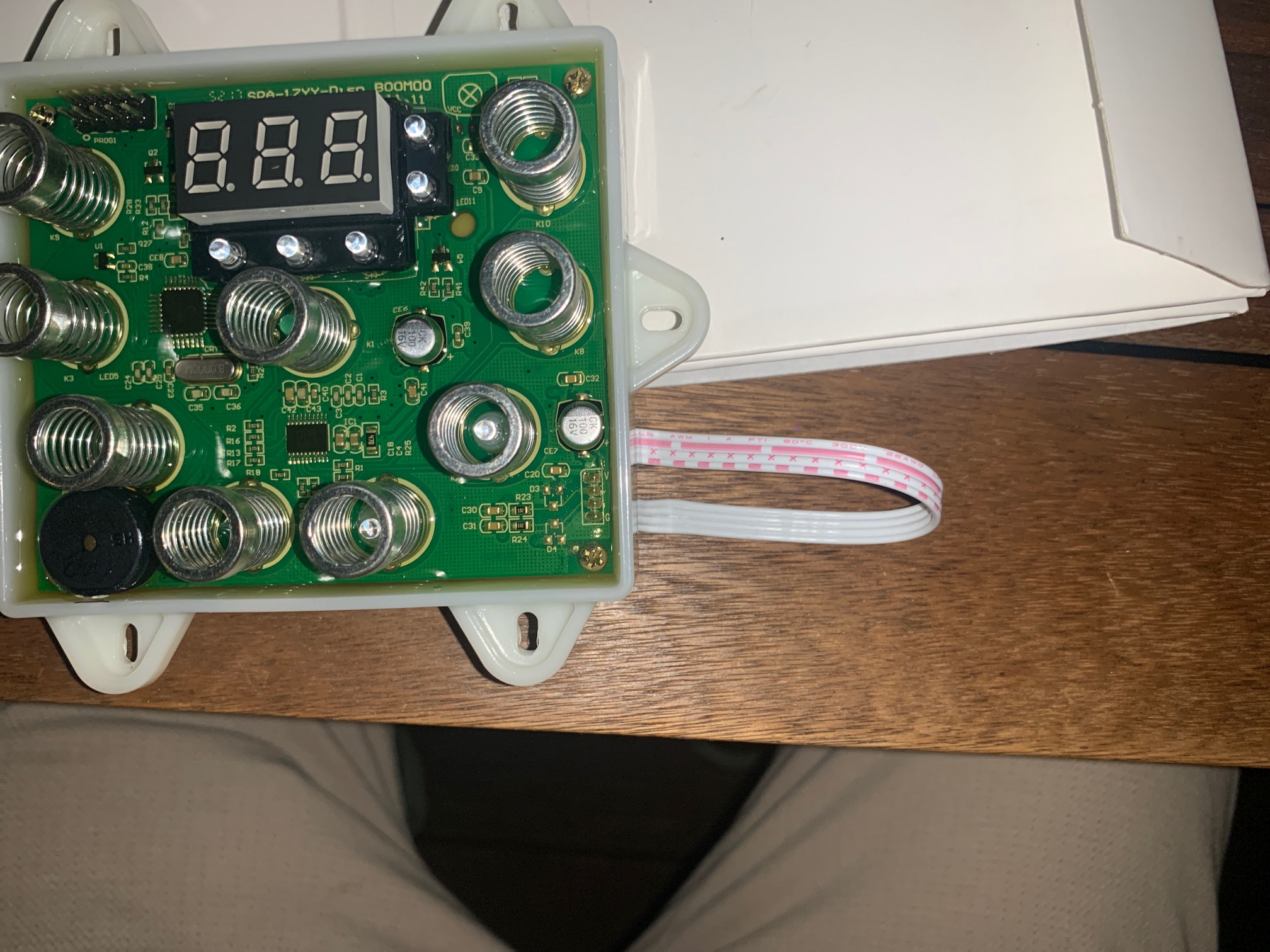
Basically I opened up the whole pump (where the display is connected to the "mainboard") And luckily i could identify the pins by pulling on the cable a bit. (on the mainboard)
In my case the small - - - was GND the ° ° ° ° was TX Long lines -- -- -- was RX And the one with the cable specifications was 5V
I hope you managed to find the right pins.
About the 5V measuring: As it is a digitally communicating device you can't measure the quick changes of the signals (0,1) with the multimeter. Small changes can be recognized as "High" or "Low" by the device. 0 does not mean it has to be 0V....could be 4,5V or something for example.
good luck
h2owasser, thank you for the clarification.
I opened my pump and found hints from the manufacturer.
Here is a photo.
Display side:
 Pump side:
 I'll try to run it on the weekend.