specify ports
a -> b: {
  source-port: some_unique_id
}
we would need
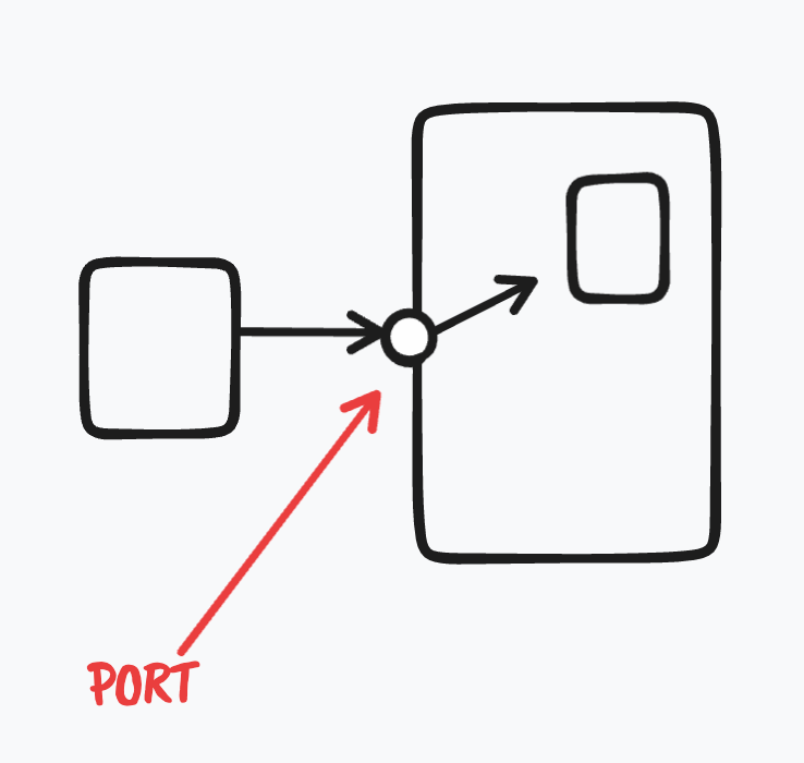
- some visual indicator of port
- enforce route sharing only between ports that are the same
- some way to specify this to the layout engines
Hi @alixander!
I am referring to out discussion over on Discord: https://discord.com/channels/1039184639652265985/1039185315685998693/1058752079105114112
Let me know if this is the wrong issue do describe my own use case.
The Use Case:
I am currently building a pretty simple tool which allows to generate some sort of system documentation based on Markdown files with some structured header (aka Frontmatter). Simply put it will allow to nest parts/components of a system (represented as a Markdown/Frontmatter file describing its Interfaces as well as the dependencies to interfaces of other parts/components) in a hierarchical matter, just as the C4 model allows to. However, one disadvantage in the C4 model is that dependencies are represented by arrows (relations) between boxes (parts of the system, a "C" of the C4, depending on the layer). What I miss here is the representation of an interface; A "Container" (lets say this is a service of some sort) might have multiple interfaces provided by its different "Components" (the "Database" can be accessed via "SQL", the "Web Service" provides a "REST" interface). I want to be able to visualize these interfaces and let components only connect to these interfaces as they describe one of the most important artifacts of an architecture.
Current Solution
Currently, generating the documentation is simply solved by rendering templates. For the visual part this is done by generating PlantUML Component Diagrams. As you can see at the very bottom of this documentation portin and portout can be specified, a label per port can be provided.
Downsides of the Current Solution
- PlantUML has not the most prettiest look out of the box
- A Component Diagram is a specific kind of diagram from the UML family, which is not what my little tool is generating. This might end up confusing readers.
- Components with no
portin/portoutare rendered differently to components with ports. This indicates a difference to the reader where no difference exists. (Currently I solve this by generating aportout(which I do not use in my approach, onlyportinare relevant) for every "box" with a label of "\n" which forces the same look on all "boxes", but this does not help the overall aesthetics). - d2 would provide a bunch of features (Markdown in "boxes") that could improve the visual documentation dramatically but are not available in PlantUML.
I hope this gives you some insights of my use case. Happy to help with testing and answering questions.
@sontags thank you for the detail, it's helpful. A few questions:
A "Container" (lets say this is a service of some sort) might have multiple interfaces provided by its different "Components" (the "Database" can be accessed via "SQL", the "Web Service" provides a "REST" interface). I want to be able to visualize these interfaces and let components only connect to these interfaces
Interesting, I would've considered these as children of a container. If I understand you correctly, you want these to be represented on the border of their parent? I presume you also care about the label of these ports? Would a tiny square like plantuml has it be the ideal representation or something else?
If the ports are such that they are all on different sides of the parent shape, is that a problem?
What else do you want to specify about the ports?
@alixander Yes, the "Components" are basically children of the "Containers" (following the C4 wording).
Side note: A nice thing about PlantUML is that both are components (this time following the UML wording), they are just nestable. parents and children are the same entity, see the following example:
@startuml
component C {
  component c1
}
@enduml
Here's an (ugly) illustration of what I trying to get
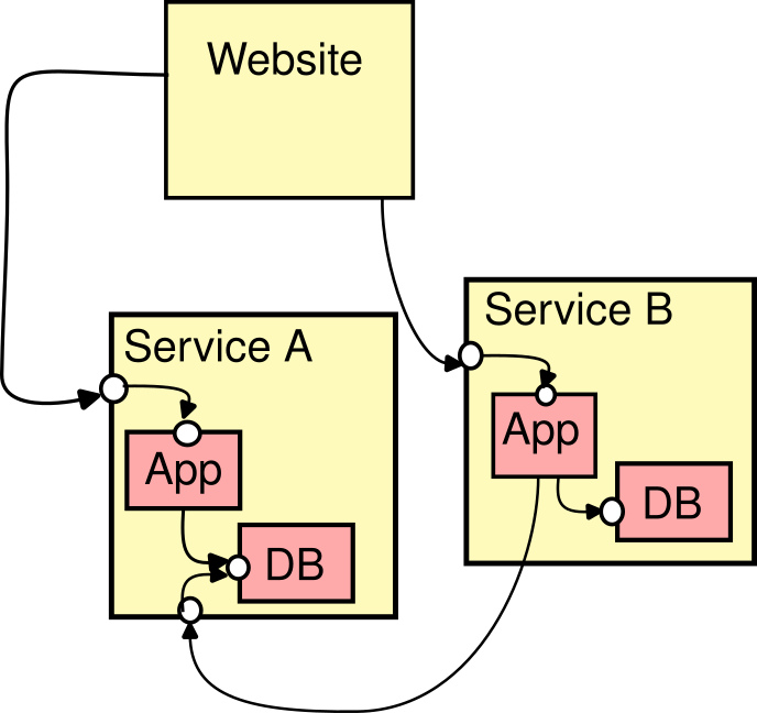
Here, the yellow boxes are "Containers", the red boxes are "Components". The Container "Website" is not specified on a Component-Level. That's by intention: If it does not make sense to get into detail documenting things (maybe it is self-explaining) then I do not want to force the user to do so...
Yes, Interfaces are displayed as a artifact on the border of the child/container. The exact shape (to me) is mostly a question of aesthetics. Labels would be very helpful: In case I want to reduce the complexity in a certain view/render and therefore omit the "Component" layer a label could still describe the interface. Ports on all sides is a good idea if it helps decluttering and prevents line crossings.
However, one disadvantage in the C4 model is that dependencies are represented by arrows (relations) between boxes (parts of the system, a "C" of the C4, depending on the layer).
This isn't quite true; the C4 model is notation independent (see https://c4model.com/#Notation), so you're more than welcome to include ports in your own notation. I generally prefer the simplicity of uni-directional arrows though, because in many cases you end up having 1 arrow (single client) to 1 port (single interface) to 1 box (single implementation), and the diagrams become unnecessarily noisy. Ports can also complicate diagram layout if several clients are using the same interface. YMMV, of course.
Right, I had understood C4 to be flexible on these matters. A method of splitting up abstractions that wouldn't have any opinion on ports, which is more in the domain of layouts.
I do see how it can get messy, as it constrains the layouts. There'd be instances where rather than a nice straight line, the connection has to twist and bend to get to that. But I think for cases like network diagrams, there's no substitute for ports -- they're probably the most important part of the diagram.
For the issue of arrow directions, I guess a single unit-sized circle wouldn't work. Two options I can think of:
-
Two circles, one for inbound, one for outbound. I think this can have unintended semantics though.
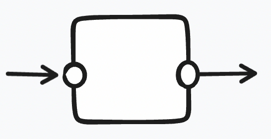
-
A rectangle with enough room to support both arrows.
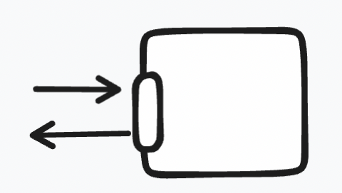
2 is trickier than 1.
For my use case, it would be sufficient to only provide interfaces that can be "consumed", as in:
        ---------------------
        |                   |
------> o                   |
        |                   |
        ---------------------
The "consuming interface" must not be shown explicit, eg. its just the box pointing to an interface:
---------------------     ---------------------
|                   |     |                   |
|                   |---->o                   |
|                   |     |                   |
---------------------     ---------------------
I see applications for both 1) and 2). However 1) could cover all use cases I can think of...
unfortunately not, still nailing more fundamental parts of D2 before adding features like this
I would also like to see this. If possible as a little square as it's defined for ports in UML. Little circles stand for interfaces. See here the overview: https://www.uml-diagrams.org/component-diagrams.html