Cell module option
Hi Stuart, Would it be plausible/possible for the cell module to not use any onboard cell balancing resistors/thermistor combo, but instead have the option to take that signal straight to a relay-- on a per cell basis --? My cells are quite large and it would be much easier for balancing if I could take the 'balance signal' and use it to trigger a much larger load for balancing that cell. Fred
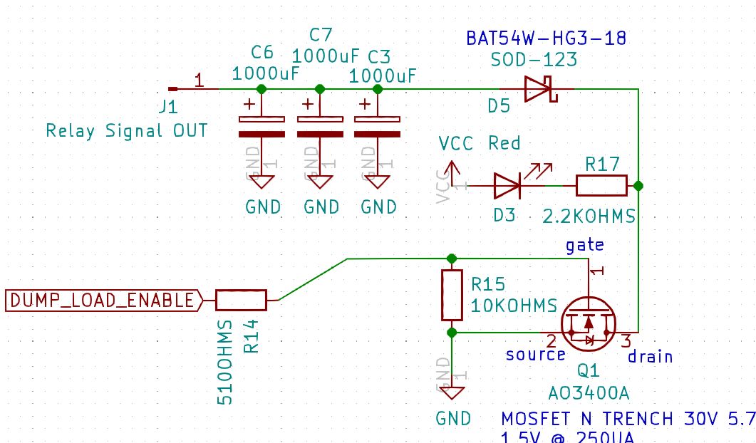
Basically, If I eliminate all the dump resistors and replace them with a two pin connector (out) and a flyback diode across those terminals (the coil), all should be good? An indicator led would also be helpful.
The code uses PWM so would want to switch the relays on and off very quickly. Would you be monitoring the balance load temperature?
Yes, an external load would be monitored but I would still need to monitor the temperature of the cell module itself. What about leaving the pwm as is and running it through a capacitor bank?
You could keep the in board MOSFET and PWM but just use another larger external MOSFET instead of a relay?
I'll look into the MOSFET idea and see if I can come up with a simple circuit. Thanks Stuart.
About that yes. The JST connect is rated up to 2amp but I would not put that through them.
I think I've got it worked out, How do I stop the dump load signal from turning off for a blip every 12 seconds? Is that in the code, (edit: yes and I can't/shouldn't)
I'm going to work out a filter circuit to eat up that pulse going to the dump load.
The dump load shouldn't be triggering that frequently. It's active high, so held low by the pull down resistor.
If the module isn't connected to the controller, every 8 seconds it should take a voltage reading, is the "blip" aligning with that?
It's unconnected to any controller, just power to the module. The module is 4.0 code version: 2021.02.24.12.59
Well I've got the module connected to the controller (working), I've got the relay connected (working) and every 13 seconds the red led indicating the dump load blinks once, it blips off then back on. No worries though, a cap keeps the relay on during that blip.
keep in mind that my cell module does not have the dump load resistors soldered on.
Hi Stuart, What do you think about this
 I'm planning on using a wire-out for the relay signal and pulling the power for the relay directly from each cell.
Would it not be easier to change the code just to remove the PWM signal? You wouldn't need all those large caps.
I'm still intrigued on the need to do this at all, do your cells really need balancing that much?
How are you preventing the external load from going over temperature?
My cells are i80p each and they were not constructed at the same time, meaning they are definitely different in capacity. Some charge up faster than others so I have a need for balancing. As far as the need to monitor the heat of the load, I'm not planning on just burning off the excess. I'm still not sure how yet, maybe lights, or using it to charge smaller cells, or a capacitor bank. I was under the impression that the PWM signal is there for a reason, so I was bypassing it. The large capacitor ratings are for when the PWM signal jumps from ON to OFF as the cell voltage decreases. If it's easier to just remove it from the code (without losing an important feature), I'll go with that.
The PWM is there for a reason, it keeps the temperature of the module down to the set level.
If you don't need that, it's fairly easy to just switch it on when needed. The bypass current counting won't work in this scenario.
So for my situation, I can disable both the PWM and bypass current counting features, along with nixing my capacitors. Will this be the same for the latest v4.4 module and the new controller?
I'm going to need help with changing the code, but not right now Thanks Stuart!
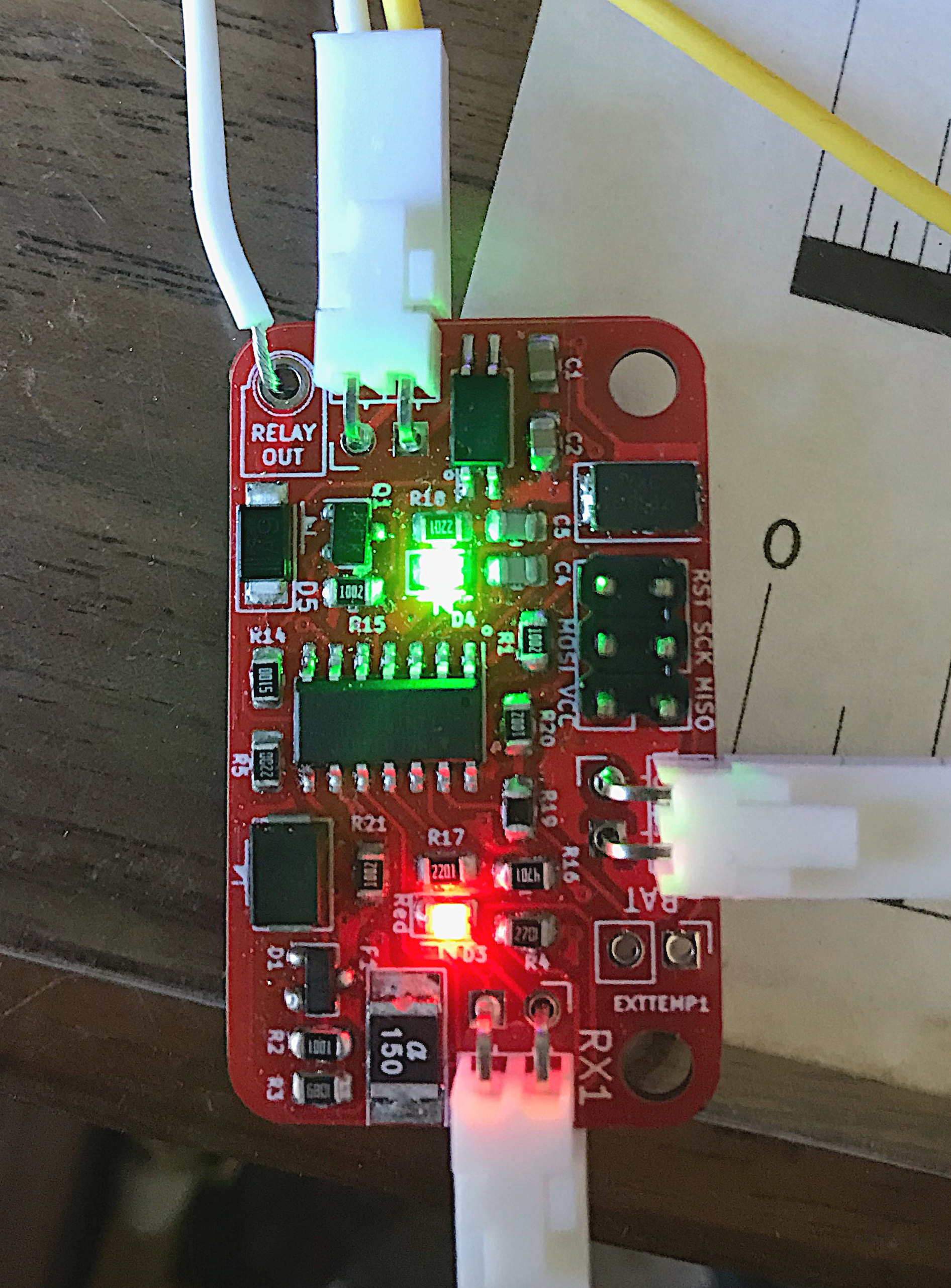
Hi Stuart, I've got my v4.4 module completed and I have successfully used the new controller to program it via the web interface. Originally I was going to use capacitors to level out that 'blip' in the discharging system, but seeing how easy it was to program the modules, I think I still might.
Here's a pic of my module and adding a cap filters out the 'blip' on my relay board just fine.