How to recover CellModules?
Hi, i might have flashed the wrong version on my cell modules (v430 instead of v421). When I try to reflash, the green LED on the module flashes once and i get the error:
avrdude: try to set SCK period to 1.6e-05 s (= 62500 Hz) avrdude: set SCK frequency to 32000 Hz avrdude: warning: cannot set sck period. please check for usbasp firmware update. avrdude: error: program enable: target doesn't answer. 1 avrdude: initialization failed, rc=-1 Double check connections and try again, or use -F to override this check.
How can i revive these modules?
Oh dear, this isn't going to be easy. The prototype v 4.3 board uses an external crystal rather than the internal oscillator. Therefore the fuses on the attiny chip are set to use an external clock.
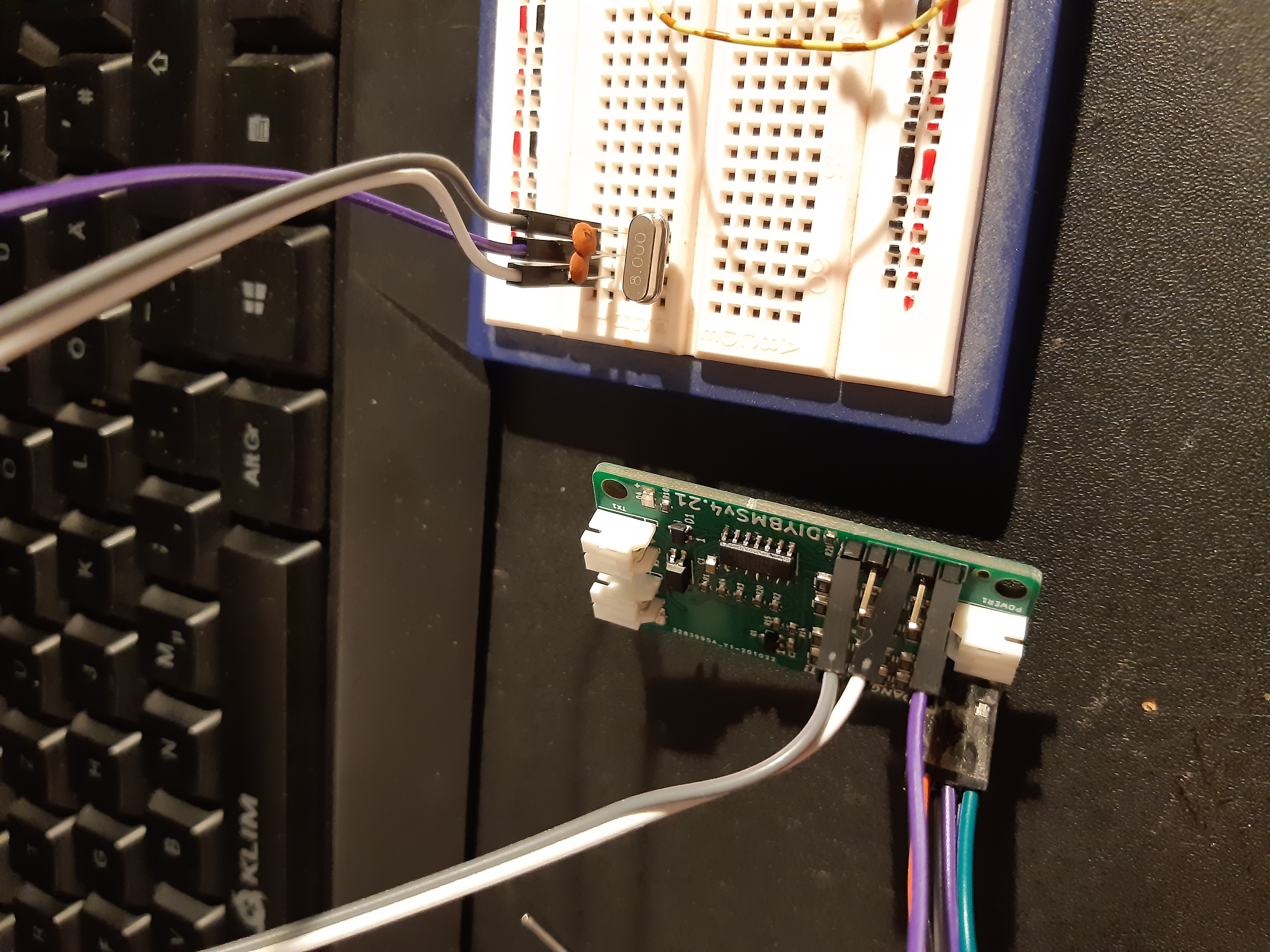
You can recover it by connecting some wires temporary to the xtal pins on the attiny and connecting them to an 8mhz crystal.
Google how to recover Arduino after wrong fuse settings, it's a similar procedure
Hi Stuart, I hooked up an 8Mhz Crystal to pins 2 & 3. But still the same error. Is there anything else I could try?
The XTAL pins (2 and 3) are connected to the SENSOR1 connector - so its likely easier to connect the crystal to this point (pins 1 and 3)
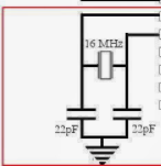
You may need to include the 22pF capacitors as well - you need to create a circuit that looks like this (but use an 8Mhz crystal)
The ground is on pin 5 of the sensor connector.
Hi Stuart,
that's basically what i did. I also connected the two capacitors to Sensor Pin5 as Ground.
Silly question, but you did provide power to the board via the ISP programmer?
Did the GREEN led light up when attempting to program to board?
Yes I did. The D4 LED flashes once when I try to program the module. It also turns on once in a while when i keep the board powered long enough.
I programmed my fuses incorrectly at first as well, and found I could recover by doing the following:
Input a 20kHz square wave into pin 1 of SENSOR1 connector (GND to pin 5 of the same connector). It doesn't have to be perfect - connect an external arduino that's just flipping an output at either 5v or 3.3v.
Use the following command line: avrdude -cusbasp -pattiny841 -B2000 -u -U hfuse:w:0xD6:m -U lfuse:w:0xE2:m -U efuse:w:0xF4:m
This gives a 20kHz clock to the ATTINY841, and programs it at 500Hz. As long as SPI is still enabled this should work. You don't want to flash it this way - a 500Hz clock takes over 5 minutes to program the ATTINY841 - but the fuses are quick even at slow speeds, and faster programming should be available once the fuses are reset. If you can provide a 1, 4, or 8 MHz clock signal, you can go faster, but 20kHz is a nice minimum that most can achieve with parts they have on hand.
But since this is really a user error (choosing the wrong firmware) I think it can be closed as such, with these notes suggesting how to resolve it.
That said, "in universe" fixes could include:
Leaving the fuses for 4.3 set to internal clock, and then selecting the external clock on startup if it's present (start it, determine if it's running or not, then switch to it. Continue with internal if it's not running correctly and send an error code to the controller).
There are lots of unused I/O on the controller board, so a fix that would use JRELAY1, or J1-J4 on the controller board to either supply the clock, or even an entire ISP programmer could be made. This would be easier on the ESP32. Of course, eventually it would be nice if the controller could update the sensor firmware over the communications bus.
Thanks for the useful recovery guide. The new ESP32 controller board does indeed have a built in ISP programmer to help avoid these problems.