Enable multiple selections of the axes of grids to be drawn
PR Details
Originally, the grid could be only drawn in one plane (X, Y or Z). This PR enables the grids to be drawn in multiple planes.


Related Issue
#158
Types of changes
- [ ] Docs change / refactoring / dependency upgrade
- [ ] Bug fix (non-breaking change which fixes an issue)
- [x] New feature (non-breaking change which adds functionality)
- [ ] Breaking change (fix or feature that would cause existing functionality to change)
Checklist
- [ ] My change requires a change to the documentation.
- [ ] I have added tests to cover my changes.
- [ ] All new and existing tests passed.
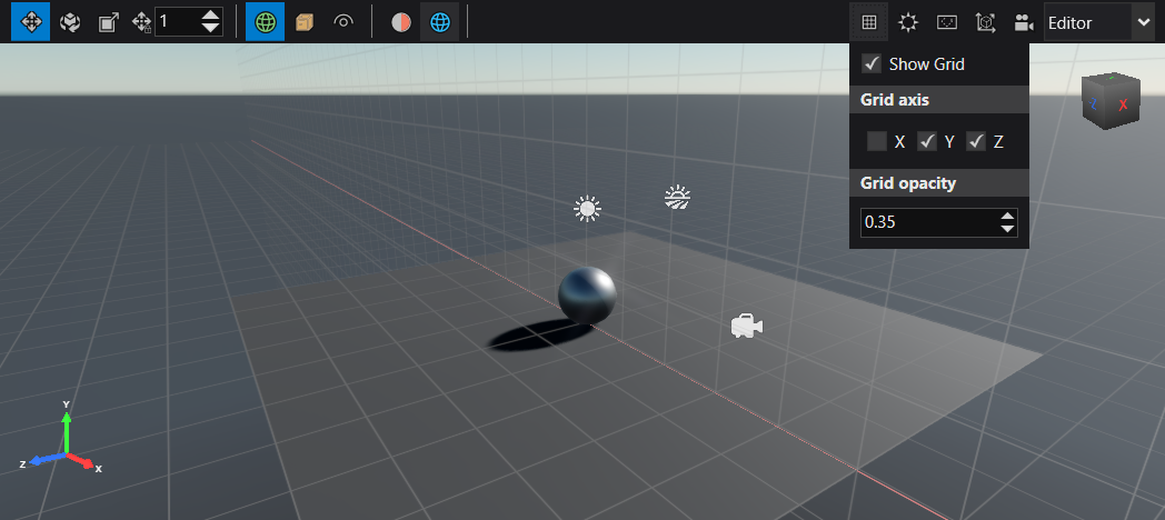
How about changing this to toggle grids for each axis instead of a radio button for each combination of axis ? i.e.:
- [ ] x
- [x] y
- [x] z Instead of
- [ ] x
- [ ] y
- [ ] z
- [ ] xy
- [ ] xz
- [x] yz
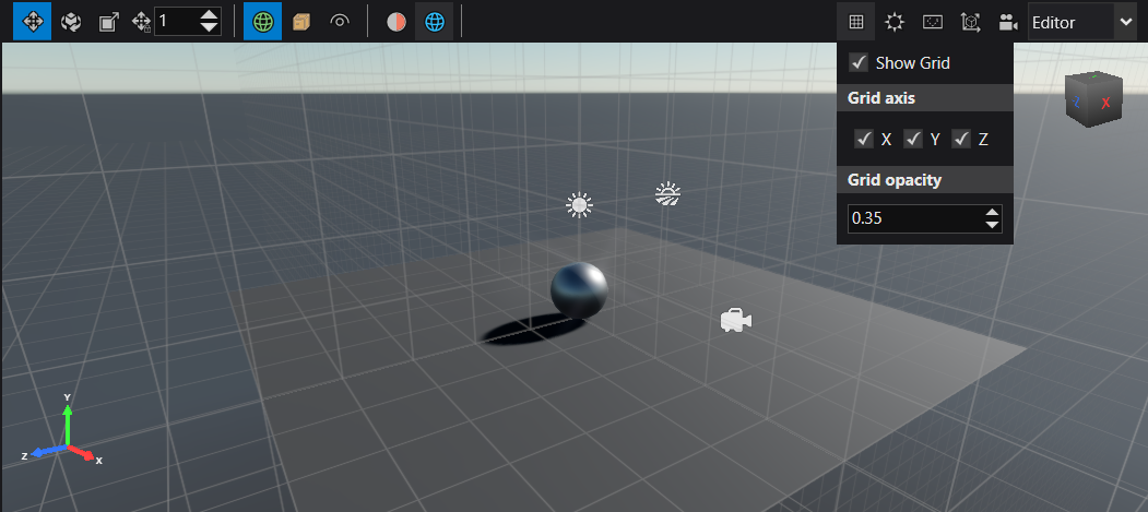
Ok, just to be clear - is the originAxes array about the colored line going along the unit axis on origin point? So in the current behaviour the flat grid has both X and Z axis. I would expect each singleton grid to have 2 axis marked, and any 2+ combination of grids to have all the axis marked. Looking at your screenshots that is not the case. Am I getting this right?
Actually I was not sure how origin axes should be marked in this case. My understanding is that, for example, if you select X grid axis, all the origin axes excluding X axis will be marked. So in the UpdateOriginAxes function, I simply disable the origin axes selected as the grid axes, which results in the behavior the screenshots just show.
I got to compile your code and first thing I noticed was that the default behavior has changed
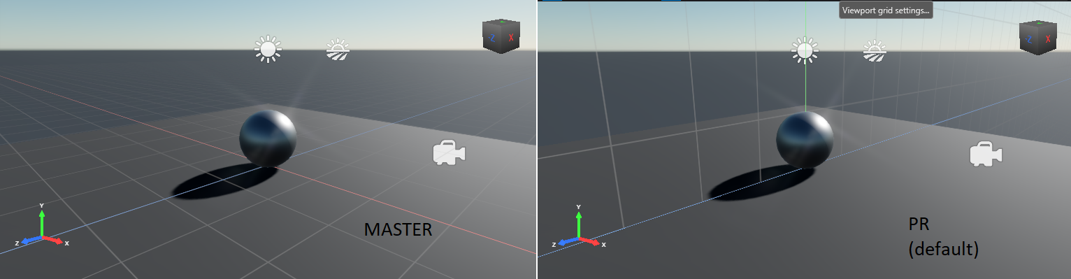 Which will be unexpected for the users. I'll let you figure it out, while I looked at modifying the axis behavior in a PR onto your branch: https://github.com/garychia/stride/pull/1
It seems that I forgot to change the default scene setting. Thanks for pointing it out. I'll try to solve it.