SPI usage: pinout allocation and read/write
Describe the bug Practical difficulties to implement SPI communication with external modules (e.g. nrf24L01) As per the Maixduino board specification, more SPI interfaces are available, although one of them is used for the TF card management. Therefore SPI1 is mapped to generic IO port, but no clear instruction how to address and read/write specific registers. Even I am not sure if the "csn" control works properly in below snippet.
To Reproduce
import ustruct as struct
import utime
from machine import SPI
from Maix import GPIO
from Maix import FPIOA
from board import board_info
from fpioa_manager import fm
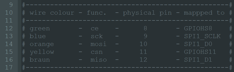
### Set up the SPI ports
fm.register(11,fm.fpioa.GPIOHS11, force=True)#cs0=csn
csn = GPIO(GPIO.GPIOHS11, GPIO.OUT)
fm.register(14,fm.fpioa.GPIOHS8, force=True)#ce
ce = GPIO(GPIO.GPIOHS8, GPIO.OUT)
fm.register(10,fm.fpioa.SPI1_D0, force=True)#mosi
fm.register(12,fm.fpioa.SPI1_D1, force=True)#miso
fm.register(13,fm.fpioa.SPI1_SCLK, force=True)#sclk
### init SPI1
spi1 = SPI(SPI.SPI1, mode=SPI.MODE_MASTER, baudrate=4000000, polarity=0, phase=0, bits=8, firstbit=SPI.MSB)
b= bytearray(1)
print("\nbefore init: ", b[0])
### init
csn.value(1)
ce.value(0)
utime.sleep_ms(500)
### prepare for communication
csn.value(0)
print("csn: ", csn.value())
spi1.write(0x03, cs=SPI.CS1)
#spi1.write(0x03)
csn.value(1)
utime.sleep_ms(500)
print("csn: ", csn.value())
csn.value(0)
# spi1.readinto(b, write=0x00, cs=SPI.CS1)
b = spi1.read(8)
csn.value(1)
ret = b[0]
print("after init: ", ret)
Expected behavior It is planned to send 0x03 command to register 0x00 Configuration register. But unfortunatelly, it is not clear how to address registers with the given SPI library.
Actual behaviour As it seems, even the "csn" state change does not work.
before init:  0
csn:  0
csn:  0
after init:  0
- IDE version: MaixPy 0.2.4
- Firmware version: MicroPython v0.5.0-200-g8f6aa7b on 2020-08-31; Sipeed_M1 with kendryte-k210
- Board: Maixduino
- OS: Windows
Meanwhile continuing the analysis, it seems to be that status of GPIO pin configured as OUT cannot be read (connecting a LED to CSN pin that it is controlled properly although the csn.value() always returns with "0"). --> It is not align with the example script https://github.com/sipeed/MaixPy_scripts/blob/master/hardware/demo_gpio_led.py where it is stated that OUT pin can be read:
led_r = GPIO(GPIO.GPIO0, GPIO.OUT) led_g = GPIO(GPIO.GPIOHS0, GPIO.OUT) led_b = GPIO(GPIO.GPIO2, GPIO.OUT) ... print("LED RGB(%d,%d,%d)" % (led_r.value(), led_g.value(), led_b.value()))
Additionally, it is not clear how CSN can be "mapped" to SPI.SPI1 in order to refer to the right csn in the readwrite statements...
Trying with the latest Maixpy release, I can find the nrf24l01 micropython ported lib in folder "..\MaixPy\components\micropython\core\drivers\nrf24l01"
Please share how should it be used
I have a similar problem with an external module. SPI1 is used by the OS for the SD card, so when you try to use it it will work faulty, for example, only CS signal but not clock etc. If you send terminal commands re defining the SPI1, sometimes the OS will drop the SD card service and it will work, other times it will crash... So at least for me SPI1 is unusable. I tried to use SPI0, everything works OK, signals work OK and you don't need to do any weird declaration, you declare mosi, miso, sclk, ss0, ss1 with the fpioa and then with the constructor, the problem is that for some reason it only reads 0000 in the MISO pin, but all the sequence is correct even the signal measured at the MISO (tested with a logic analyzer). So, at this moment the M1 module has 0 available SPIs for being used with Micropython.
Here is the code for SPI0 (the brd_ports is just a list of my board's ports, replace with your own):
fm.register(brd_ports['IBS_MOSI'],fm.fpioa.SPI0_D0,force=True)
fm.register(brd_ports['IBS_MISO'],fm.fpioa.SPI0_D1,force=True)
fm.register(brd_ports['IBS_SCLK'],fm.fpioa.SPI0_SCLK,force=True)
fm.register(brd_ports['IBS_CS0'],fm.fpioa.SPI0_SS0,force=True)
fm.register(brd_ports['IBS_CS1'],fm.fpioa.SPI0_SS1,force=True)

spi = SPI(SPI.SPI0, mode=SPI.MODE_MASTER, baudrate=1000000, polarity=0, phase=1, bits=8, firstbit=SPI.MSB)