pico-feedback
 pico-feedback copied to clipboard
Datasheet: SMT Footprint
The datasheet (currently v1.9) shows the following dimensioned drawing for the recommended SMT footprint.
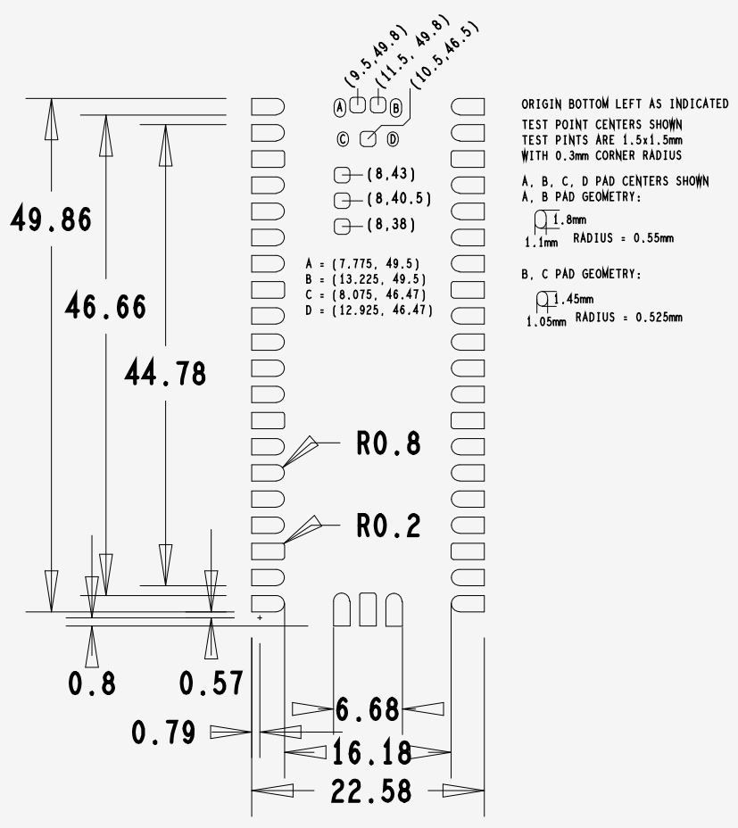
As a minor point, the legend to the right currently indicates "A, B PAD GEOMETRY:" and "B, C PAD GEMOETRY" (which should likely read "C, D ...").
More importantly, while all necessary dimensions are included, some improved clarity / accessibility would be fantastic! It's currently a bit of a maths exercise / eyesight challenge to deduce the necessary dimensions.
I admire the efforts that have gone in to documenting the RP2040 family - while this change isn't technically required, I believe it would reduce friction and improve accessibility significantly, especially for folks who are just starting out.
I'd also encourage you to make use of the fantastic hi-res images you've got in the PDF (vector or otherwise)... I'd be curious to know how many people are drawing up footprints from a direct A4 printout - I don't think legibility in that format would be top of my list for a technical drawing like this.
I've included some example drawings below, and would be happy to offer feedback on revisions or share the sources. (Hopefully my figures are correct!)
The test points and pads A,B,C,D are already well defined, based on centers, so I've omitted them below... (thanks!)
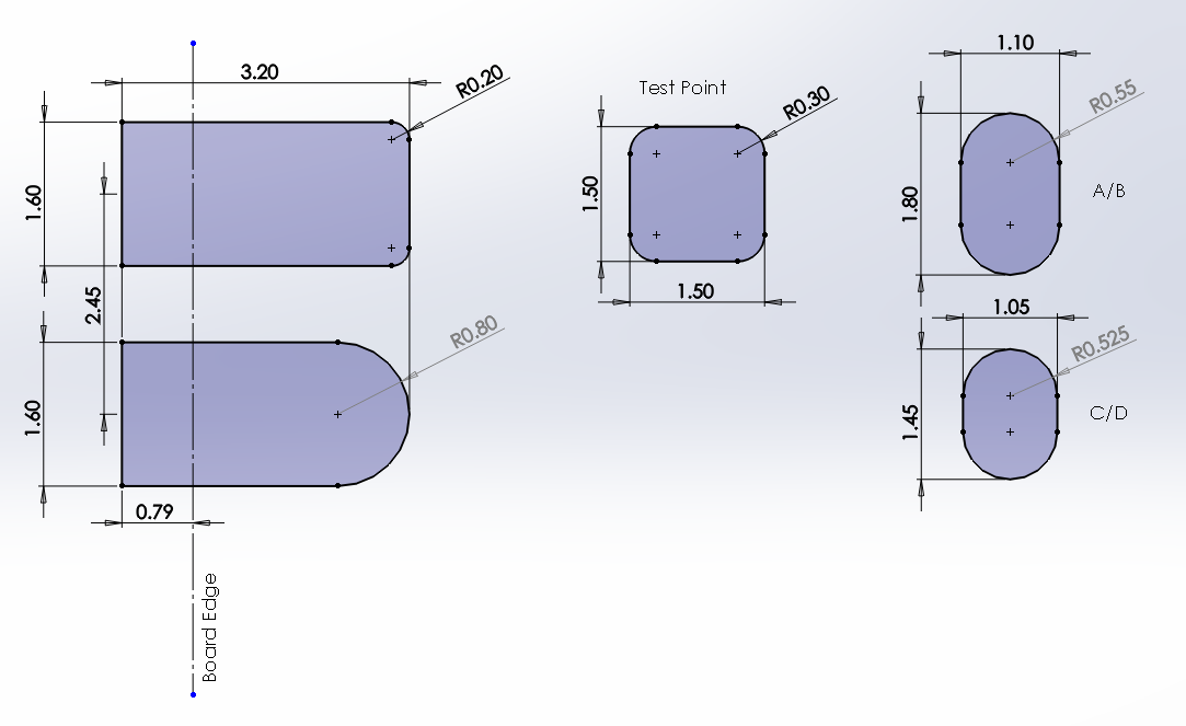
Clear pad dimensions, defined separately
In the first diagram, introduce the pad shapes that are in use, and dimension / label them clearly.
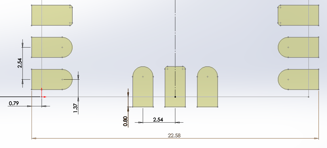
Pad positions
Then, provide an overview drawing that shows the pads and their locations in a more simplified manner. For example, the pads running up the left are first located on the board origin (bottom left), and then have their Y position by center, and it's a repeated 2.54mm pitch... pads on the right side are a direct mirror.
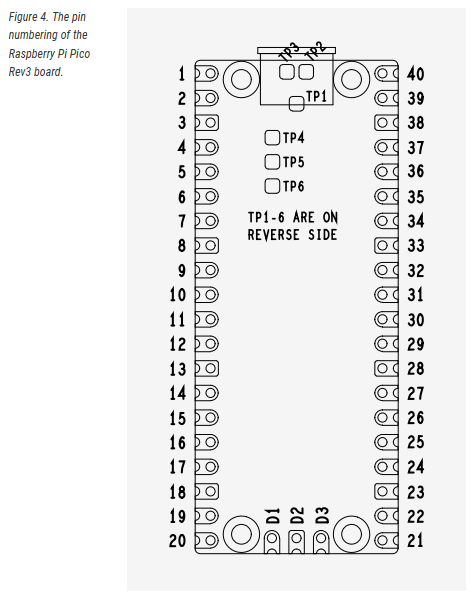
Top / bottom view label
Another easy mistake to make when drawing up footprints is understanding whether the view given is from the top or bottom.
Figure 4 in the datasheet shows the pin numbering, and comments that TP1-6 are on the bottom... however features on the "other" side are often marked in dashed lines or similar. As there is no explicit "this view is from the top" label, this may lead to confusion - though I know it can be deduced from other drawings, it's not immediately apparent.
+1 -- These changes would greatly help the process. None of the public libraries AFAIK implement this correctly. [Still applies at version 2.4.] And I second the motion that overall the docs are excellent.