Radek
![]()
Radek
I am sorry. I overlooked my involvement there is a problem with the description of the connector in the V1.2 board version
Use English. You can use Google translate. You probably used FW with the wrong configuration. Compile your own FW with the correct parameters. In the future, you will be able...
Close the ticket
On the E1 and E0 controllers, just cut the pins in the DIAG connector and everything works as it should :-)
So you don't have to cut anything. Just remove the Jumper at the respective motor controller 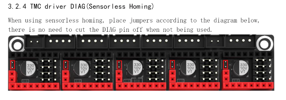
If you remove the diag jumper under the engine E0 and E1, you can use connectors E0DET and E1DET according to your configuration. They are not physically configured to X...
The pin file is fine. If you define X_MIN stop in configuration.h and enable sensorless guidance, X_MAX is not defined.
you should set //#define X_DUAL_ENDSTOPS //#define Y_DUAL_ENDSTOPS #define X_HOME_DIR -1 #define Y_HOME_DIR -1
Then comment the lines //#define X_MIN_PIN PC2 // E0DET //#define Y_MIN_PIN PA0 // E1DET
https://github.com/bigtreetech/MINI-12864/blob/master/mini12864_v1.0/Hardware/BIGTREETECH%20MINI12864%20Interface.pdf Only this