Can we talk about dimensioned drawings?
I'm curious why there's no open enhancement discussion for displaying or exporting dimensioned drawings. I'll leave the spec open for now but I could see a few ways to achieve this. There is so much power here, yet it's not mentioned often, so this feels like a philosophical/motivational conversation before a tech one.
The exercises use dimensioned drawings ask the student for something. It seems natural to me, if you're reading an OpenSCAD drawing, you'd want to see these sometimes as well. One use case is you want to fabricate by hand from a drawing or compare an object to a drawing, measurement by measurement.
In 2013 Canny Machines put up a layer solution of sorts, but it's made clear there are some tradeoffs with that addon.
What are people's thoughts about some sort of builtin support for automatically maintained, optional, dimensions?
Thanks for reading.
Want to back this issue? Post a bounty on it! We accept bounties via Bountysource.
[ I should note that I know almost nothing about the guts of OpenSCAD, However, I have thought a bit about what this problem means. ]
It would be cool.
And I don't immediately see how it could work - at least without some significant additional infrastructure.
Consider this OpenSCAD program.
cube([100,1,1]);
translate([100,0,0]) rotate(90) cube([100,1,1]);

translate([-10,-10,0]) text("A");
translate([100,100,0]) text("B");
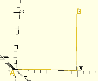
I want a dimensioned line from point A to point B. How would I say that?
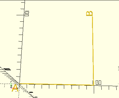
The program itself demonstrates the problem, in how I had to separately calculate where the two points are to position the labels. One could perhaps do a little better by locating the labels "close" to their points, e.g.:
cube([100,1,1]);
translate([100,0,0]) rotate(90) {
    cube([100,1,1]);
    translate([100,0,0]) text("B");
}
translate([-10,-10,0]) text("A");
but note that even there I had to duplicate the second cube's dimensions in positioning B. More importantly, the B label is inside the "rotate", so is rotated:
One might imagine some kind of scheme where you could "mark" a point and then later refer to it, something like:
mark("pointA");
cube([100,1,1]);
translate([100,0,0]) rotate(90) {
    cube([100,1,1]);
    translate([100,0,0]) mark("pointB");
}
dimension("A", "B");
Given that, to the extent that OpenSCAD executes programs at all, it executes them before doing the associated geometry work, I don't know how possible this is. (You almost certainly can't have a function that measures the distance from one point to another and returns it.) Maybe you could have the marks and dimensions be objects that - at geometry time - record their absolute positions and generate an appropriately-shaped object. I don't know if even that would work; I don't know if even at that point the object "knows" where it is. It would be entirely sensible for the object generation process to generate an untransformed (untranslated, unrotated, unscaled) version of the object as a mesh, and for the infrastructure to then transform it as appropriate. Such a scheme also assumes that the geometry processing has a notion of one thing happening before another - the dimension line couldn't be generated until the two marks are recorded - and today it doesn't necessarily have such a concept.
And then there's the question of how this would interact with the programming aspects of the language. What would happen if one of the marks was inside a module or loop so that it was instantiated multiple times?
Consider
cube([100,10,10]);
for(x=[10:20:90])
    translate([x,5,0]) cylinder(d=10, h=30);
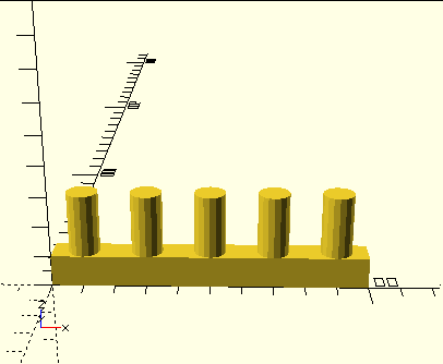 and you want to have one dimension line showing how tall the cylinders are.
It's easy enough to build an object that looks like a dimension line, and position it wherever you want, but it wouldn't be tied to points in the model and automatically maintained. I've got a measuring stick module like that - but to use it I have to manually position it to where I need it. (Rather like a real measuring stick.)
I realize that my examples above are trivial. It's always difficult to come up with examples that are easy enough to be understood, but complex enough to demonstrate problems. Let me leave you with one where I'd have to do a small pile of math to figure out the right answer, and where rendering "inside" the transformation would yield stupid behavior.
module skewz(x, y) {
    multmatrix([
        [ 1, 0, x, 0 ],
        [ 0, 1, y, 0 ],
        [ 0, 0, 1, 0 ],
        [ 0, 0, 0, 1 ]
    ]) children();
}

skewz(.2,.2) cylinder(h=20,d1=10,d2=0);
translate([20,0,0]) skewz(-.2,-.2) cylinder(h=20,d1=10,d2=0);
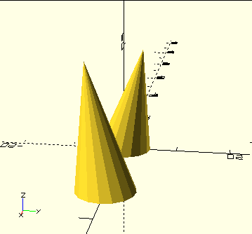 Measure the distance between the two points of the cones.
(Continuing to think out loud...) There could be a pass through the geometry tree, after it was created and before actually generating the meshes, that applied the transformations so as to accumulate a list of the "global" coordinates of the various marks, that would then be available during the mesh creation for the dimensioning object.
Sounds plausible, but not a trivial addition.
And note (as indirectly demonstrated in my examples), often the marks that you want are not at the object's local origin, but rather at some other point on the object. One answer is to separately calculate how the desired point relates to the origin of the object, as I did in the second example. (But that's not necessarily fun; the location of the points of the cones isn't trivially obvious.) Another, far more complex, answer would be to somehow add marking to the primitive objects - so that, for instance, when you create a cube you could place marks at any of its eight corners. You would leave it to the object to figure out exactly where the marks went. You'd also have to leave it to the object to define where marks could go. For a cube, you might want them at the corners, at the centers of faces, at the centers of edges, et cetera. You'd need a micro-language to say which point on the object to use for the mark.
I'm very new to OpenSCAD, but just wanted to express how useful this would be. My main purpose for OpenSCAD is design for 3D printing, but I decided that to learn the application best I should draft something I'm currently building... in this case a new workbench made from dimensional lumber. While the drafting went great and I love the results (aside from finding out the hard way about rendering and colors), for actual production (i.e. carpentry by hand) I'm going to need to either print the drawings and annotate them by hand, or export and import into another program that can handle adding dimensions...
I wonder if adding dimensions might be easiest via interaction with the rendered scene? It could snap to lines and vertices, and just make it easy for the user to add dimensions where they need them. Wherever the cursor is in the source file the dimension tool could insert a function call including the coordinates (or a point/line reference of some sort) and any other data required to show the dimension line as it had been positioned by mouse.
dimension([[0,1,0], [2, 1, 0]], direction='up', offset='12')
It seems like trying to reference arbitrary vertices from source code would be really cumbersome, and nobody would want to dimension.
A 2D sketch tool that output polygon coordinates into the text editor would also be really cool.
Any news on this? I really like the simplicity and lack of ambiguity of openscad but the inability to output a technical drawing just kills it for fabrication.
I've done a little with this since the comments above, but all in the form of modeling dimension lines into the model, like so:
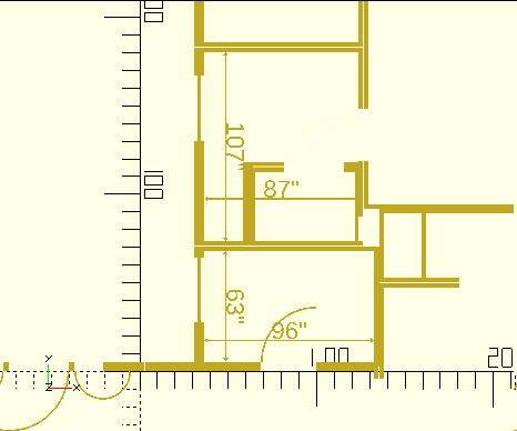
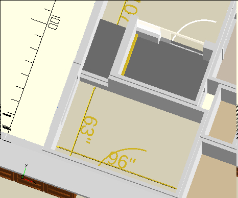
That "drawing" is not generated automatically by OpenSCAD. Rather, the modules that I use to define walls have a mode that instead generates 2D shapes. Its more "natural" 3D mode looks like so:
The dimension lines are explicitly added in the model. I have a module that takes two points and draws a dimension line between them.
I've done a little with this since the comments above, but all in the form of modeling dimension lines into the model, like so:
That "drawing" is not generated automatically by OpenSCAD. Rather, the modules that I use to define walls have a mode that instead generates 2D shapes. Its more "natural" 3D mode looks like so:
The dimension lines are explicitly added in the model. I have a module that takes two points and draws a dimension line between them.
Can you provide some code for that floor plan thingie?;)
Full sources for some version of my house are at https://www.thingiverse.com/thing:4264614/files . I don't happen to remember whether that version includes the 2D option or the dimension lines. But note: calling it a "floor plan thingie" overstates its capabilities. It does not automatically generate dimension lines; it does not even really know what a room is. It knows how to create a wall, with openings. Where does the wall go? That's up to you. If you want more information, send me e-mail at openscad -at- jordan.maileater.net.
OpenSCAD bot: this issue is stale because it has been inactive for 360 days. It will be closed if no further activity occurs within 60 days.