Can Someone Send Me an Original Controller?
I fried my PCB trying to implement a power workaround for Issue 8. Would someone who has discarded theirs be willing to send me theirs? Happy to pay for shipping.
More details. Module C158 on the back burned up when plugging in 24v power repeatedly. I think it was because I had it sitting on the metal frame, but I am not sure.
For clarity, this is what I need:
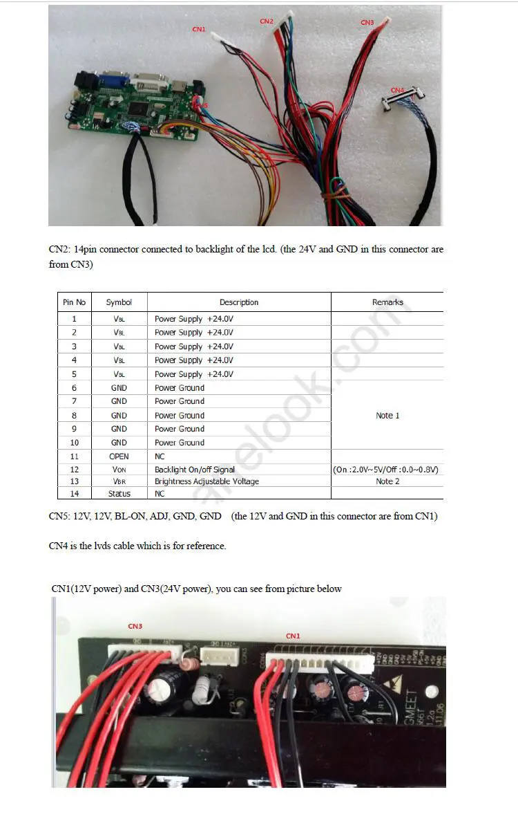
Are you changing out to this board? https://www.ebay.com/itm/166580220209 I have it connected right now and I think I may end up removing the old board completely. If you run this board from eBay, I think you can pull power from the PSU and new board to power the display and backlight. The seller provided a couple images for helping connect it. I removed the jumper on C1 and put the power switch there (original switch location).
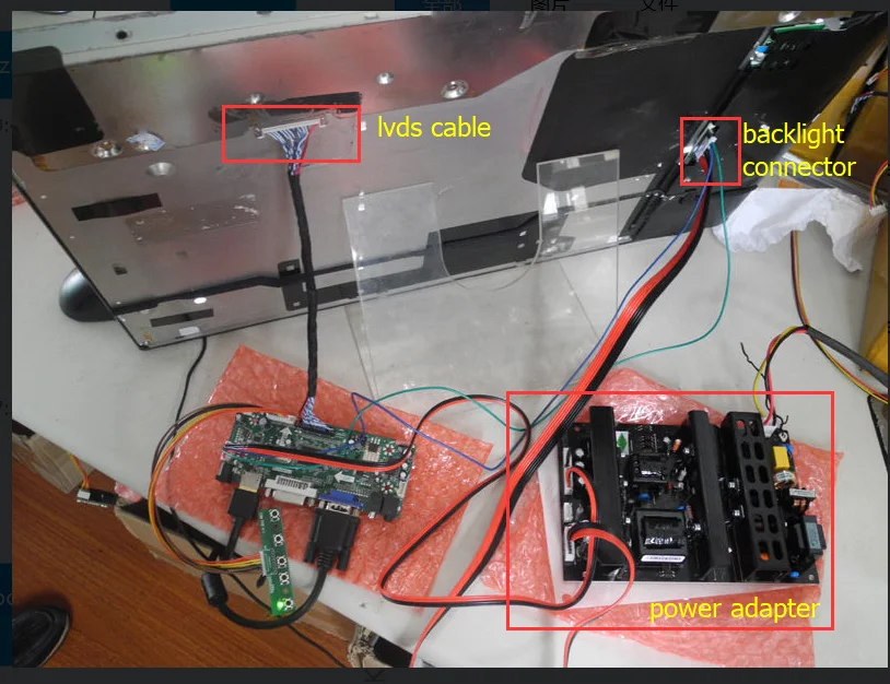
eBay seller’s images
My images
Top picture is my current build state running entirely off the new board.
I’m also planning to try audio direct from the new board, which will require some rewiring/repinning. I can’t figure out how to wire audio from the new board’s L/R +/- connections to the amp. The old board had more connections. I’ve removed what looks like a speaker amp and I’m going to straight connect to the board. Might be weak but hopefully it’ll have some sound.
I want to wrap the wires over the PSU with some 80C electrical tape. Old wires had coating over them with that temp rating. I’m also waiting on some standoffs to arrive. New board’s wire lengths mean it needs to mount in the middle somewhere.
I’m not ready to declare the new board the only feed I need yet. I want to put some hours on it to see how it does. Seems like it’ll work though.
Yes. Same board.
On Tue, Apr 2, 2024 at 1:03 AM Jeremy Fields @.***> wrote:
Are you changing out to this board? https://www.ebay.com/itm/166580220209 I have it connected right now and I think I may end up removing the old board completely. If you run this board from eBay, I think you can pull power from the PSU and new board to power the display and backlight. The seller provided a couple images for helping connect it. I removed the jumper on C1 and put the power switch there (original switch location).
eBay seller’s images [image: image 1] https://camo.githubusercontent.com/be5d1723a7c9ebb43e7e6e3bf29b362d6aa21edfad004b1ac29d303a06674157/68747470733a2f2f616530312e616c6963646e2e636f6d2f6b662f4854423178655a324b6b7a6f4b31526a535a466c7136796934565861542e6a7067
My images Top picture is my current build state running entirely off the new board. IMG_2074.jpeg (view on web) https://github.com/olm3ca/mirror/assets/87494419/f18f76b8-0a18-449d-b333-86914ea73af9 BC8FC4B2-E79A-436A-BB86-238E11E00E4D.jpeg (view on web) https://github.com/olm3ca/mirror/assets/87494419/fcae0ea9-d1cf-4810-8a3d-c66a030c16ed IMG_2043.jpeg (view on web) https://github.com/olm3ca/mirror/assets/87494419/ecdcfbcf-b665-428c-b17f-e3915da7e5fe
I’m also planning to try audio direct from the new board, which will require some rewiring/repinning. I can’t figure out how to wire audio from the new board’s L/R +/- connections to the amp. The old board had more connections. I’ve removed what looks like a speaker amp and I’m going to straight connect to the board. Might be weak but hopefully it’ll have some sound.
I want to wrap the wires over the PSU with some 80C electrical tape. Old wires had coating over them with that temp rating. I’m also waiting on some standoffs to arrive. New board’s wire lengths mean it needs to mount in the middle somewhere.
I’m not ready to declare the new board the only feed I need yet. I want to put some hours on it to see how it does. Seems like it’ll work though.
— Reply to this email directly, view it on GitHub https://github.com/olm3ca/mirror/issues/10#issuecomment-2031141254, or unsubscribe https://github.com/notifications/unsubscribe-auth/AE4ERUMKLQF3RF4WAG5MB2TY3JC4LAVCNFSM6AAAAABFRAEEKWVHI2DSMVQWIX3LMV43OSLTON2WKQ3PNVWWK3TUHMZDAMZRGE2DCMRVGQ . You are receiving this because you authored the thread.Message ID: @.***>
Do you still need the board? My mirror is working fine without it. I'm powering the backlight and display using the new eBay board only. I turn it on for a few hours a day with a managed outlet, and it's been running like that for a about a week now. You should be able to do the same. If you want help with connecting the new board's power, let me know. If you still want the old board, I am not using my old one.
Would love some help getting the ebay board to power this thing.
On Sun, Apr 21, 2024 at 10:56 PM Jeremy Fields @.***> wrote:
Do you still need the board? My mirror is working fine without it. I'm powering the backlight and display using the new eBay board only. I turn it on for a few hours a day with a managed outlet, and it's been running like that for a about a week now. You should be able to do the same. If you want help with connecting the new board's power, let me know. If you still want the old board, I am not using my old one.
— Reply to this email directly, view it on GitHub https://github.com/olm3ca/mirror/issues/10#issuecomment-2068393905, or unsubscribe https://github.com/notifications/unsubscribe-auth/AE4ERULRZSDMJITE7X36OY3Y6R35XAVCNFSM6AAAAABFRAEEKWVHI2DSMVQWIX3LMV43OSLTON2WKQ3PNVWWK3TUHMZDANRYGM4TGOJQGU . You are receiving this because you authored the thread.Message ID: @.***>
Original power supply unit (PSU) setup. Power is going to the old mainboard and the microphone. There's also the Mirror's main on/off switch. I removed all of these, and unpinned the on/off switch for reuse on the new boards connectors. Some of these were hot glued down; I pulled the glue off and was able to disconnect.
Top of the mirror; other end of the power cords. This is the old mainboard, camera, and microphone board. I removed everything, but then reinstalled the camera lens & board (no connections) so there's wasn't an obvious hole where the old camera and lens were. The mainboard receives power in a couple connections, with one of them double pinned to feed power out to the speaker board. I removed the speaker board as well (not shown - near PSU). I think that board is an amp and audio routing. I did try sound without it by temporarily wiring the speakers to the new board, and it worked fine, but I don't have a connector for connecting the speakers directly to the new board (I just rigged it for testing).
New board connected for testing. It's proving power to the TV/Monitor and backlight. TV/Monitor control button panel is wired but was later removed since there's no way to access these buttons from outside the mirror casing without a lot of work, and it wasn't really needed for this project. I may have used it to select input once - don't recall. Jumper cable versus power switch was still installed - see pic immediately following this one. You can replace that loop with the switch wiring, or leave it as-is and manage power with a smart switch or some other method. I liked the idea of having the switch wired, but in practice I have the power connected to a smart switch with a timer to turn the monitor & backlight on/off (on in the morning, off for bed).
If you want to keep the switch, you can removed the cable from the old connector by depressing the tooth type metal bit, and pushing the pin & wire out from bottom of the connector. Once it was out, I pulled the teeth back up a little for better locking again in the new connector. Similar thing to remove the loopback cable, then insert the switch cords where the loopback was. Make sure you get the right holes since there's a bunch of empty pins there - I don't think color/polarity matters since you're just opening/closing a switch.
Completed project. I tried to route the cables to keep them from being too wild. Also, the original power cables were wrapped in 80°C jackets. New cables are not like that, so I used electrical tape with a similar rating and just wrapped the cords since they're running across the PSU. The Raspberry Pi is powered with its own cord.
Hope this helps. Let me know if something isn't clear. Here's a bunch of related pics. https://imgur.com/a/ztgrLKG
@jeremy-fields I finally got around to copying your helpful notes into a new page of the repo specifically for users with this panel. If you notice anything I should update, let me know.
Thanks @olm3ca. I did see one error in my original post. I just edited my post on Issue 8 from:
I did have to move some pins around to get the plugs right. If you do this, pay attention to the +/- because the colors are not always correct - I found red wires connected to negative connections.
to:
I did have to move some pins around to get the original power switch to work versus always being powered on (removed loopback wire on new cable, installed switch wires in its place).
I did some repining in the beginning when I was trying to keep the old scalar board, and I did come across some bad +/- red/black cords where they were switched. I ended up removing that board so that repinning is irrelevant and has added some confusion. The only repinning I did (that stayed) is to pull out that loopback cable on the new board's power connector and move the power switch's cords to there. I talk about it more in this post. Specifically the pictures immediately before and after this text:
If you want to keep the switch, you can removed the cable from the old connector by depressing the tooth type metal bit, and pushing the pin & wire out from bottom of the connector. Once it was out, I pulled the teeth back up a little for better locking again in the new connector. Similar thing to remove the loopback cable, then insert the switch cords where the loopback was. Make sure you get the right holes since there's a bunch of empty pins there - I don't think color/polarity matters since you're just opening/closing a switch.
In summary, my original words in the first quote are incorrect and should either be removed or reworded. My second quoted block is clearer, or choose your own words. No need to repin anything, unless you want that switch versus always on.
@jeremy-fields on the topic of a reset to maintain backlight, my unit does open to a OOPS YOU'RE NOT ON WIFI screen. However, after about 5-10 min the backlight does shut off. I did notice that while in the ON position overnight it did maintain the wifi signal for an AD HOC wifi but the backlight did not come back on. Before I proceed, do I need to ensure the backlight stays on? Definitely harder with this older model and a lack of reset button.
Could someone provide a part number or working link to the "ebay board" referenced above – the ebay link no longer works.