API coordinate system
I'm currently working on wrapping hrtf crate in the GStreamer plugin. I was wondering if you could help me to clarify some of the API constraints?
Those are the questions:
- do coordinates passed to the processor have units? meters for instance?
- if not, do they have to be normalized so they are in the range [-1.0, 1.0]?
- is the coordinate system left or right handed?
- what would be an example of static object positions that correspond to 5.1 speaker layout with the listener at
0.0.0? E.g. would that work for front left/right speakers:
FrontLeft => Vec3 {
     x: -1.45,
     y: 0.0,
     z: 2.5,
 },
FrontRight => Vec3 {
     x: 1.45,
     y: 0.0,
     z: 2.5,
 },
Thank you for all amazing work
Hi!
- The crate does not accept points, only vectors. So it does not care about units, all it needs to know is a sampling vector to fetch data from HRIR sphere.
- Input vectors will automatically normalized.
- HRIR spheres using right-handed coordinate system. (Ping me if you need to know how to make it use left-handed coordinates)
- These vectors should do the job, yes. The crate using HRIR sphere so you can use any vector to emulate sound coming from various direction (even top and bottom).
Thanks for the explanation.
From the documentation I can read that sampling_vector is a vector from source to listener. So for a given position P(x, y, z) in a right handed coordinates the sampling vector will be the vector in opposite direction so Q(-x, -y, -x)?
And this is what I'm observing, when I use sample_vector let's say (1, 0, 0), I was expecting that the positive x corresponds to the right side of the listener (assuming listener is at (0, 0, 0) , but it is exactly opposite.
Also a hrtf example from rg3d-sound shows the same. The position set on source (spatial.set_position) changes clockwise, so going from the front to the right side. But if you listen to rendered sound it is clearly going an exact opposite direction, so to the left first.
Am I missing something?
Now I'm not sure if documentation is right about coordinate system 😅 . I seems that I got confused when writing all of those.
Let's take a step back. If you listen to an output of hrtf example and compare with how source position changes over time, do you think it is an expected outcome?
The start position of a source is at (0, 0, 3) and then the source position updates moving clockwise on the circle, the sound produced by this code does the exact opposite. This is a confusing part.
TBH, I think the hrtf crate documentation is right when it says that the sampling_vector is a vector from the source to listener, but if you use rg3d-sound as reference how to use it, it looks like rg3d-sound just uses left-handed coordinate system and it never translates it to what is expected by hrtf crate.
It's me again :)
I looked into this a bit further and the problem I'm seeing originates from the code that creates hrir binaries. I thought I would draw how the hrir coordinates look now and compare to right handed and left handed coordinate system.
For simplicity I draw only 2d plane, as all the variants have the same understanding of elevation.
This is created by this octave code
1;

function [x, y, z] = lh_coords(azimuth_rad, elevation_rad)
  azimuth_rad = azimuth_rad .+ pi/2;

  x = cos(elevation_rad) .* cos(azimuth_rad);
  y = zeros(1, numel(x)) .+ sin(elevation_rad);
  z = cos(elevation_rad) .* sin(azimuth_rad);
end

function [x, y, z] = rh_coords(azimuth_rad, elevation_rad)
  [x, y, z] = lh_coords(azimuth_rad, elevation_rad);
  z = -z;
end

function [x, y, z] = curr_hrtf_coords(azimuth_rad, elevation_rad)
  elevation_rad = pi/2 .- elevation_rad;

  x = sin(elevation_rad) .* sin(azimuth_rad);
  y = zeros(1, numel(x)) .+ cos(elevation_rad);
  z = -sin(elevation_rad) .* cos(azimuth_rad);
end

azimuth = 0:30:330;
elevation = 15;

azimuth_rad = azimuth ./ 180 .* pi;
elevation_rad = elevation / 180 * pi;

[x, y, z] = lh_coords(azimuth_rad, elevation_rad);
## [x, y, z] = rh_coords(azimuth_rad, elevation_rad);
## [x, y, z] = curr_hrtf_coords(azimuth_rad, elevation_rad);

plot(x, z, '*', 'MarkerSize', 16)
hold on
grid on

set(gca, 'FontSize', 16)

axis([-1 1 -1 1])
xlabel('x')
ylabel('y')

for n = 1:numel(x)
    text(x(n) + 0.05, z(n), num2str(azimuth(n)), 'FontSize', 16)
end
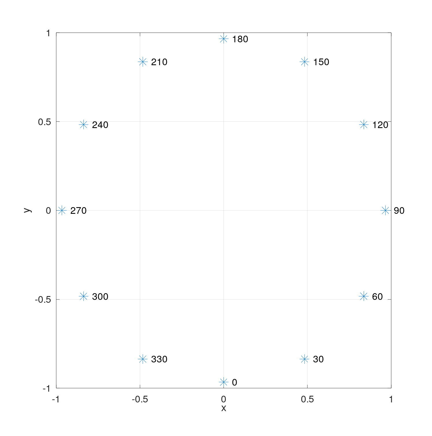
1. Current hrir coordinates:
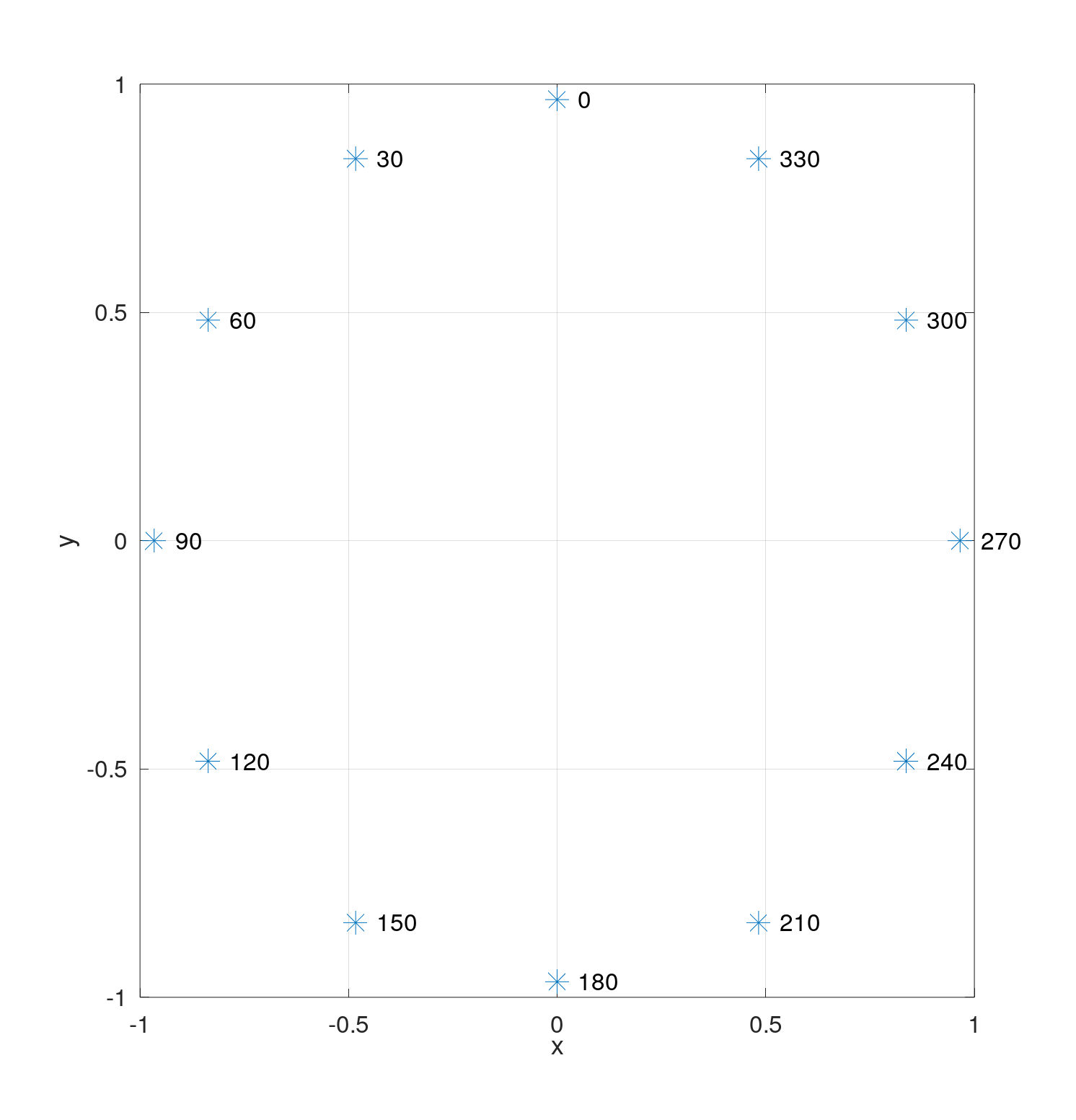
 2. How
 left handed should look like:
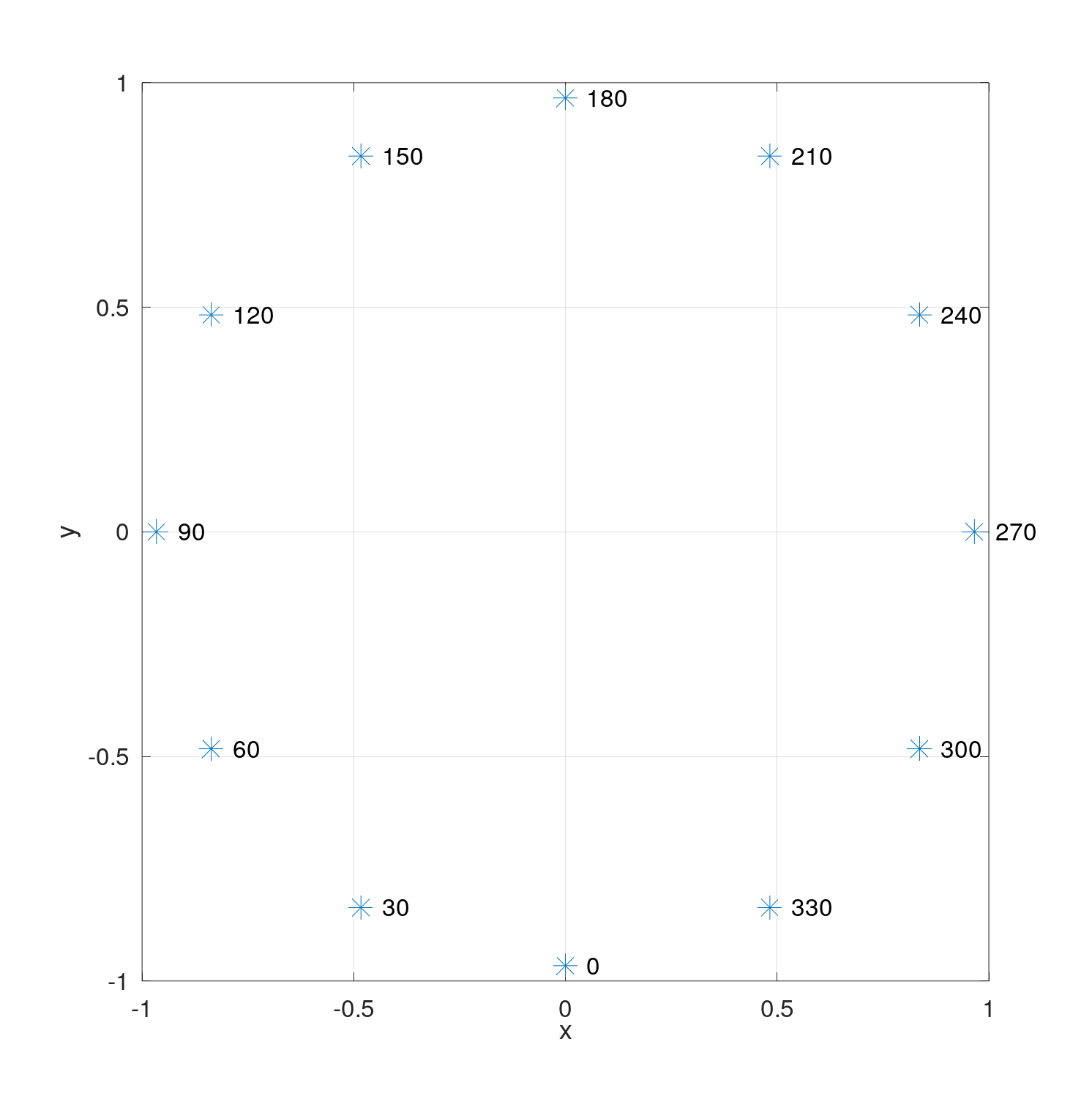
 3. How
 right handed should look like:
IRCAM database uses following format:
- azimuth: azimuth in degrees (3 digits, from 000 to 180 for source on your left, and from 180 to 359 for source on your right)
- elevation: elevation in degrees, modulo 360 (3 digits, from 315 to 345 for source below your head, 0 for source in front of your head, and from 015 to 090 for source above your head)
Currently to choose hrir that corresponds to e.g. 30 degrees azimuth, both x and z need to be negative.
This shows that, hrtf crate does not use Right Handed system even though docs says so. My understanding of LH vs RH is that they only differ in z sign. But here they differ in sign for both x and z.
It is also not a vector from the source to listener because an elevation is not inverted.
@mrDIMAS Please let me know your thoughts. I think the binaries generation could be fixed to use RH or LH or if not it should be very well documented that the coordinate system is something different.
I can prepare PR if you decide to fix it in https://github.com/mrDIMAS/hrir_sphere_builder
No worries, this is amazing job. Do you have any preference: LH vs RH? I didn't spend much time looking at what rg3d-sound is doing, but it looks like it assumes LH coordinates for hrtf renderer. If it is so, picking LH coordinates for HRIR would not require any changes there.
The docs says Hrtf spheres made in *right-handed* coordinate system., so it is either to fix generator to use RH or LH and fix the docs. I'd like to have it in right-handed because rg3d game engine uses RH coordinate system too.