RPiCoffee
 RPiCoffee copied to clipboard
Electronics tutorial
Hi,
Ive seen this project and was really amazed and want to try it for my machine too.
However I have no clue about the electronics - how to connect the Pi and the machine in detail.
Are you still planning to do a noob-friendly tutorial? Would be awesome!
Cheers
Have checked out the shoppinglist, however it is incomplete. Firgured I would try and make it work through the pictures. But I can't seem to find the PCB board/interface where all the parts are soldered to.
Sorry for my late response! I forgot to set any notifications on github. Thank you very much for your feedback, it is nice to hear that you are interested!
Yeah, I will definitely work on a tutorial/rework the circuit diagrams. Currently, I am a little bit busy with my Masters thesis but I will find some time ;-)
Do you have the gerber files for the pcb? Then I can order it and try already!
hi there, I just uploaded the whole KiCad Project to the repo. My PCBs were made by Oshpark where you can upload your KiCad files directly without plotting gerber files. In case you want to use some other service, I exported the gerber plots in a separate folder.
I also included the schematic as PDF.
Please pay attention to the missing route between resistor R10 and R11. I spotted that error when the PCBs where already produced. You reroute it or just solder some wire by hand to fix that. I included a screenshot of KiCad where I marked that area on the layout.
Hope that helps so far!
Awesome! Thanks, that will definitly help. Did you add a file where the error or R10 and R11 was fixed, or should i fix it manually as you said?
No it is not fixed.
You can fix it manually with soldering a wire as shown here: https://github.com/misteu/RPiCoffee/blob/master/schematics_KiCadProject/missedRouting.jpg
On that photo you can see how it looks on the finished PCB: https://github.com/misteu/RPiCoffee/blob/master/docs/images/PCB_soldered.jpg So, pretty easy. If you managed to solder all the SMD stuff on the board, this one will be the most relaxing work ever 😅
If there is enough space on the PCB to fix that route, that would be the more elegant solution. But honestly, no one notices that PCB when it is built in 😄
Could you perhaps update the shopping list you created? Or it the shopping list actual, on Reichelt?
hi there, for soldering the interface circuit you just need the stuff I put into that table here in the wiki: https://github.com/misteu/RPiCoffee/wiki/Shopping-list
You will find all the parts if you search for them in your favorite electronics store. All of these are pretty common parts.
In addition to that you just need the RPI, a power supply and very thin wire as described in the wiki entry.
Thanks, ordered the PCBs. But I see that you updated the shopping list, now I am not able to find all the parts anymore on reichelt. Could you perhaps send me the actual reichelt list? Makes it allot easier to order for me.
hi there.
You can still find everything on reichelt. Just type in the part number to the search field.
Pin headers straight are called "Stiftleiste" at reichelt. You can buy these: https://www.reichelt.de/rnd-stiftleiste-8-pol-rm-2-54-mm-rnd-205-00629-p208855.html?&trstct=pol_3
You can order them four times (1x 1x08 and 9x 01x02) and break them apart to get the 01x02 headers
The transistors (BC847) you need are these: https://www.reichelt.de/bipolartransistor-npn-45v-0-1a-0-3w-sot-23-rnd-bc847b-p223362.html?&trstct=pos_0 make sure you buy transistors with the case type called: SOT-23 (like in the link above)
The resistors you can find here: https://www.reichelt.de/0805/2/index.html?ACTION=2&LA=2&GROUPID=8397 You can find the right value via the filter on the left, you need 10k, 5.6k and 200 each one eight times. They cost pretty much nothing. So I would buy e.g. 100 of each value (1,2€ per value). They get lost easily and you can uses them for some other projects, too.
The optocouplers are these: https://www.reichelt.de/optokoppler-ltv-817-p76173.html?&trstct=pos_3
you can solder the optocouplers directly onto your PCB or use some sockets. I don't know if there are 4pin sockets available. I did not found them, so I cut apart these: https://www.reichelt.de/ic-sockel-8-polig-doppelter-federkontakt-gs-8-p8230.html?&trstct=pol_1
You can buy theses wires to connect/solder your front panel buttons to the interface PCB: https://www.reichelt.de/index.html?ACTION=446&LA=3&q=kupferlackdraht I would not buy something thicker than 0.2mm because there is not much space if you want to connect all the buttons.
To connect the copper wires to your interface board's connectors I would use these wires, because they already have the right connector: https://www.reichelt.de/flexible-drahtbruecken-7-cm-buchse-buchse-10er-pack-steckboard-mbbvt-p177393.html?&trstct=pos_0 just cut them apart and solder them to the copper wires.
Everything is pretty standard stuff so you could also look on ebay for cheaper offers. I ordered a lot of electronics parts on ebay.
I hope that helps.
Alright, thanks! So the parts you linked are all the parts I need, in the correct number?
Yeah for the interface PCB that should work. But I suggest you look at the circuit and do check if everything is on the list. That will help you also to understand the circuit a little bit more.
And of course you need the raspberry pi. You will also need some pin headers and jumper wires for connecting the raspberry pi to the interface PCB. There are also shops offering the raspberry pi with pre-soldered headers for a few euros more. If you buy a handful of jumper wires you have enough for soldering them to the copper wires and for connecting the PCB to your raspberry. Jumper wires with a length of 10cm are pretty good. I would buy 50 of them or something like that on ebay.
So I would not count every single piece of the circuit ;) Overall, the parts are pretty cheap, even if you buy everthing double ;)
May I ask if you did any bigger soldering projects before that?
Just to be clear: I am not responsible for any damage on you or your coffee machine! Please make sure, that you know what you are doing when soldering on your coffee machine and connecting wires to it.
If you got everything together I would strongly suggest to test every single circuit on its own. If you do one big test in the end its quite annoying to find the error. A good practice is to test every optocoupler circuit with terminal commands.
Thanks! Ordered the parts. This is my first ‘big’ soldering project. Did a few small projects with Wemos and ESP8266.
Now when the parts are in, I can get started. Do you have a overview where I can easily see which part goes where?
I looked in KiCad while soldering. Actually it's eight times the same circuit. So if you finished one or two of them you will know which part goes where ;-)
I reinstalled everything on my rpi today, because something crashed some weeks ago which made it inaccessible. I don't know why this did happen, maybe the logfiles grew to big or something like that.
Long story short: It's a good practice to make some kind of backup of your SD-card as soon as everything works. I didn't had that.. :( Spent some hours reinstalling everything by hand :-/
Feel free to open another issue if you got any problems setting up the rpi or the software.
Already got myself a Raspberry pi zero w with Homebridge running. Made it completely self-maintaining, so I won’t have any work with it again. But its always a good idea to make a backup image. Even if it is just for safe-keeping. In a few weeks, when I got the time to solder everything together: “Hey Siri, make me a cup of coffee.” :)
ah nice! I didn't heard of Homebridge before :)
self-maintaining sounds great, I hacked something together on a fresh Raspian Jessie install.
haha I like that idea of connecting the machine via homebridge to siri 😄
Do you have a high resolution picture of the soldered PCB? I am having a hard time figuring out which goes where.
Do you have KiCad installed? To look there is the safest way to solder the parts to the right spot. There is also a 3D Model Viewer built-in. But I prefer the PCB view where you can just right click the connections and see which part goes there.
Anyway, I can make some photos today because I want to reinstall the updated RPI to the machine. But I can't promise high resolution pictures 😄
Currently, no. I will get to installing that. The KiCad files provided will generate a 3D model? That would be very helpful. The schematics are gibberish to me, when it comes to actually soldering the parts where they belong.
A few close up pictures of the circuits would be great, will make it a bit more 'alive'. :)
The 3D view looks like this:
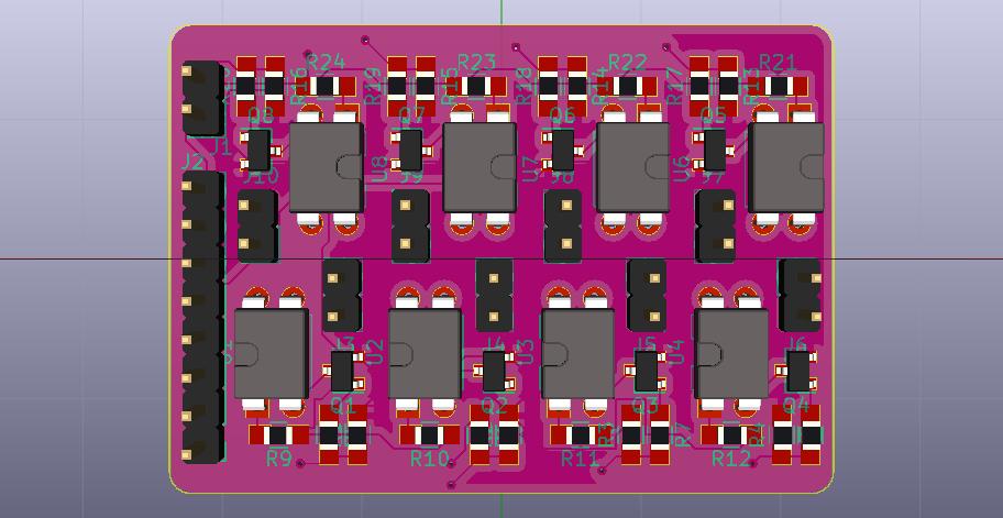
E.g. you can see that there is R23 directly above one of the optocouplers following R15 and R19 from right to left. All of these eight circuits follow the same pattern. I designed one of them and copied it eigth times, than routed everything.
If you look at the circuit diagram you can see the values of R23, R15 and R19:

I see, that makes it fairly easy to determine which goes where. Thank you! Reichelt just shipped my order, so hopefully it will arrive later this week for me to give it a try.
After several attempts, I did not succeed. Soldered three pcb’s according to the manual, with the correct resistors and such. Double checked everything, but no signal comes through.
However, when I connect the wires from the machines board (on/off button) to the pi zero directly, it does work. So it is safe to say the problem lies in the pcb. I am not that much of an electronics expert, so I am wondering what is wrong with connecting the wires from the machines board to the pi zero directly?
Hi, I'm sorry for that. You double checked every connection I assume? Maybe you damaged some transistor while soldering. They are pretty easy to destroy when heating up too much or too long. I remember that I dumped some of them when I had the feeling that I gave them too much heat.
I did not connect them directly for three reasons:
- I did not want to mess around with (or think about) the machines signal levels. The RPi works with 3,3 or 5V, the machine: I don't know. The custom PCB separates both power supplies and both logical levels. The word for it is galvanic isolation, the optocouplers make sure that there is no current running between the machine and the PCB. If you connect the RPi directly to the machine, you could also get problems with noise and as a result very undefined switching of your buttons.
- If there would be some short circuit in an RPi without galvanic isolation to the machine, the machines PCB could be damaged as a result of that short circuit.
- The RPi's output drivers are not designed for directly driving loads permanently. The transistor makes sure that the outputs load is never above that limit for permanent loads.
Alright, so the PCB is necessary. Maybe an odd question, but since I cannot get it to work, would you be able to make the board? I am willing to pay for that, ofcourse!
Currently, I am a litte bit busy writing my master thesis. I can't say for sure when I got time for it.
In general, I could do the soldering if you provide the parts needed. I have got spare parts from my build but I am not sure if there is enough of everything for a second one. I am a little bit low on optocouplers I think. If you take care of them I could do the soldering (on ebay they are pretty cheap).
Maybe you could send me your PCBs as well and I could take a look at them first (and run some tests on it). Maybe it's just some small error/broken part. It would be a pity to throw them all away, because this board can be used for a lot of projects connecting anything to a RPi (like relais and stuff like that).
That would be amazing! I think it would be better if we discuss this in private, so I can send you the parts. I will ofcourse send all the spares I have. Is there a private messaging on GitHub?
I don't know but you can visit my website (mic.st) and scroll down to my email adress. I do not want to post it here due to spambots.