convolve
 convolve copied to clipboard
How to generate kernel_params, and go beyond 6 of them?
Context: https://twitter.com/rickbrewPDN/status/1562499054952534018
The kernel parameters listed at https://github.com/mikepound/convolve/blob/master/complex_kernels.py are a set of 6 hardcoded 4-vector arrays. I've been having difficulty determining how these are actually generated, and how I might generate kernel parameters beyond the 6 that are listed here (as in, how to calculate for 7, 8, 9, etc.). The explanations I've found are not close enough to my comprehension of the math involved ("it's just a Gaussian kernel with a complex width" ... ??!! 😂 from: http://yehar.com/blog/?p=1495). Every example of Bokeh blur code I've found online lists the same set of pregenerated kernel values, with no code showing how to actually generate them.
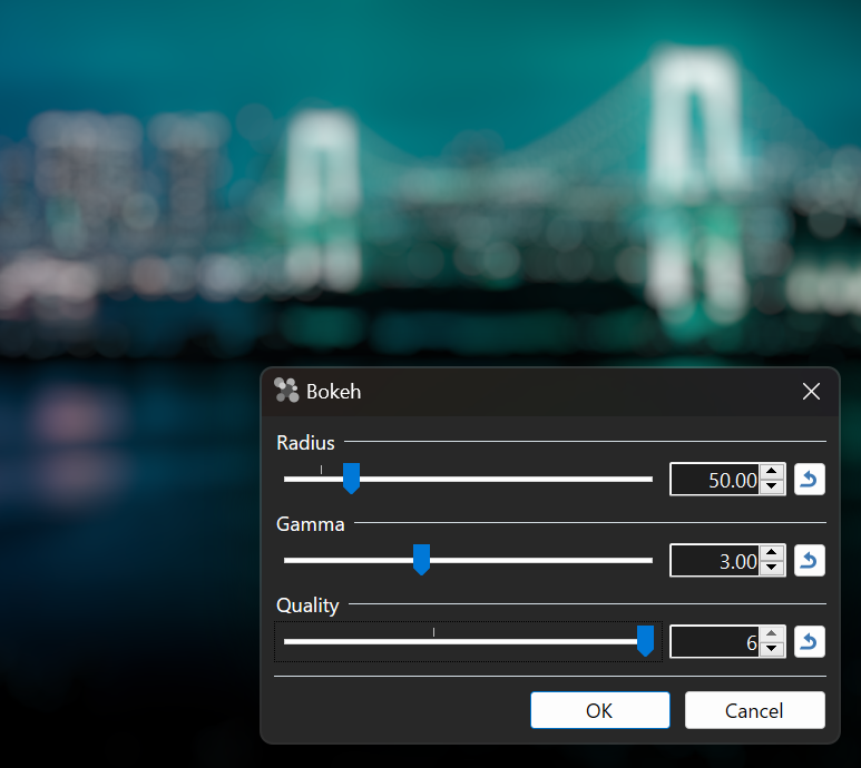
My motivation is to experiment with higher "quality" settings in Paint.NET's new Bokeh blur filter. "Quality" is a slider in the UI that controls which set of kernel parameters are used, which is then tied to the number of rendering passes.
Ringing artifacts are present when there's an imbalance between quality, radius, and the gamma exponent (default is 3). I'm hoping to extend the range at which these values can be combined before artifacts are noticeable (or even eliminating them, if possible). My rendering pipeline is fully 32-bit floating point per pixel component (128-bits total), so there's a lot of room for extra precision vs. the typical 8-bit RGBA32.
My dream solution here would be a function that takes in an integer for the # of components, and returns an array of 4 vectors for the kernel parameters. For example, generate_kernel_parameters(2) would return [[0.886528, 5.268909, 0.411259, -0.548794], [1.960518, 1.558213, 0.513282, 4.56111]] (the numbers from https://github.com/mikepound/convolve/blob/master/complex_kernels.py). I'm not sure how feasible or computationally expensive that is though.
cc @Sergio0694 @saucecontrol @jimbobsquarepants
This is a very interesting problem :) But it's also turning out to be quite a challenge! Not having the facility to do this myself was something that bugged me at the time of writing my original code, so this has been fun. This said, I have little in the way of optimisation experience, so this was a steep learning curve!
TL;DR
After some moderately successful attempts of my own, I actually found the original source code for the optimisation at the end of the blog post. With my own optimisation in Scipy I was fairly close, but unable to obtain the extraordinary accuracy of the original kernels beyond about 4 components. I think there are a couple of reasons, but primarily python is terribly slow for this, maybe 1000 times slower than the C++ implementation. I could probably close the gap a bit with some careful optimisation, but it doesn't seem like a good use of time. I'm going to focus instead on cleaning up and adapting the C++ implementation - it is super quick.
The best results I have so far is running the C++ global optimiser (more on this below) then passing the result through the python local optimiser for a polish. This also has the side effect of increasing the precision of the decimals we have for all component sizes.
Optimisation of kernel parameters
Prior to finding the original code, I came up with my own optimisation approach. As it happens this is fairly close to the one used in the C++ implementation. The function we're trying to fit is some kind of finite impulse response. It's generally zero outside of the range -1 to 1 (called the stop band), and 1 within this range (pass band). There is a small transition between 0 and 1, it looks like this:

To optimise you need to code a cost function that measures how good a given set of parameters are. My cost function ended up being pretty similar to the C++ one, which is a sum of squared error from the computed kernel, and this ideal curve. I also had some success in measuring the actual ripple in both the pass and stop bands. The problem with the optimisation is that it's extremely easy to be stuck in local minima, i.e. a broadly good fit to the data but not the actual minimum ripple possible. I tried many different optimisation algorithms, but because it takes a long time in python, if they are finding their way to a great solution, it's too slow to spot!
Here is an example of a 6 component kernel that fits pretty well, but the ripple is just a little too big:

I also made use of the SciPy differential evolution approach that is used in the C++ version, but it's too slow to converge in python. My best result was about 50% bigger than the original kernel (which in the grand scheme of things is nothing, but it's not good enough). I could probably match the performance of the original if I worked at it, but I've come to the conclusion my time would be better spend adding features to the C++ version. For example, donut bokeh, exploring different transition band sizes and so on.
C++ Optimiser
The original source code is right at the bottom of the blog. Most of it is aimed at reading and writing PNGs and doing the complex kernel convolutions (which here is implemented via fourier transforms - probably faster but I don't think in PDN case it's a huge issue either way), does PDN use FFT convolution?). I've stripped out all of the code to do with images and left only the kernel optimisation in. I ran the 7 component kernel on our servers overnight for 1 billion (lol) iterations, and it's absolutely nailed it. I then took the parameters and tweaked them using a local search (DE and others are global search, better for getting out of local minima, but need fine tuning at the end). The result is great:

It's small, but you can basically see the ripples of the 6 component above and below the 7. The original 6 component model has a ripple size of 0.0012 compared to the new 7 component ripple size of 0.0038, 3x smaller!
Next Steps
I'm running 8, 9, and 10 component models now on our servers. I'll add some numbers when they come in. I'm not sure what's causing the ringing in PDN's implementation, but I suspect that when you use a high gamma / kernel width, this essentially scales up the kernels massively, causing even small ripples to become a bigger deal. We will see I guess if higher component sizes help. There may be other issues such as the size of the kernel (in pixels) compared to the mathematical one within it, but that's probably something to look at later.
I'm going to re-optimise the lower component counts too as I think I can push the accuracy higher than the original post through a combination of running it longer, and fine tuning. For now, here is the 7 component model:
[a b A B] [5.635755002716984, 2.0161846499938942, -127.67050821204298, 189.13366250400748] [6.2265180958586, 6.010948636588568, 255.34251414243556, 37.55094949608352] [6.189230711552051, 8.269383035533139, -132.2590521372958, -101.7059257653572] [4.972166727344845, 12.050001393751478, -0.1843113559893084, 27.06823846423038] [4.323578237784037, 16.00101043380645, 5.837168074459592, 0.3359847314948253] [3.6920668221834534, 19.726797144782385, 0.010115759114852045, -1.091291088554394] [2.2295702188720004, 23.527764286361837, -0.07655024461742256, 0.01001768577317681]
It's probably worth putting this in and seeing if the banding goes down in extreme cases. It was noted by the original author that pushing the components up and ripple down has the side effect of increasing some of the component weights (A, B). This probably isn't an issue at the precision you're using, but with gamma we might want to go over some numbers to make sure there isn't a chance of overflow in extreme cases.
I'll post again when I have more numbers, and I'll start messing around adapting the C++ code, will post that code up soon.
Wow, thanks for the detailed explanation! Well if it takes server(s) running overnight to generate these, that certainly answer my question about whether these could be generated at runtime: no :)
I added the 7th component and it does reducing ringing a little bit:
(with 6)

(with 7)

The first 6 kernels I have are only specified with 6 decimal points of precision:
// 3 components
new Vector4Double[]
{
    new Vector4Double(2.17649, 5.043495, 1.621035, -2.105439),
    new Vector4Double(1.019306, 9.027613, -0.28086, -0.162882),
    new Vector4Double(2.81511, 1.597273, -0.366471, 10.300301)
},
Do you have the first 6 with these higher precision values like you do for the 7th? That might also help the ringing a little. It may be prudent for me to cap the gamma at a lower value as well. Edit: I plugged in the set of 6 higher-precision numbers from the blog and it produced a null output (all zeros), so those numbers seem incompatible.
Using the high gamma values may require 10 or more passes to get rid of the ringing for good, but we'll see as the numbers come in
Also, I assume that the kernel scale for the 7th set of numbers is also 1.2?
private static IReadOnlyList<double> KernelScales
{
    get;
} = new[] { 1.4, 1.2, 1.2, 1.2, 1.2, 1.2, 1.2 };
That looks much better, I agree that (assuming ripple continues to decrease) 9-10 components should see very negligible ringing. How long do these effects take to compute on the GPU? There are a lot of convolutions happening here, but I consistently underestimate GPUs :) Are we talking "live preview" kind of speed? Or just acceptable for a click and see how it looks.
I will re-run the optimisation with different component amounts and try to extract the higher precision numbers, they should all support this but it'll probably only make a notable difference at 5+ components.
My guess is the width multiplier will be the same for 7+ components, but we should probably check e.g. a 64 width and see if point sources are approx 64 pixels across once it's done. I can't remember exactly why I did this, but I think I tried to match the width to what looked good because the edge of the disc has a kind of slope to it. Maybe I decided that the blurred edge of the disc should count within the width, rather than outside it - a judgement call for PDN I think. I suppose the main goal is that regardless of which kernel quality you use, you want the actual blur to be roughly the same size. I think the reason that most of the kernels are the same size and only the 1 component is different is simply because it's a much worse shape, and so the ring ends up smaller and needs to be scaled.
Passable kernels probably appear fairly quickly even on a laptop, but I don't think it'll be possible to optimise at high quality sufficiently quickly. If we wanted to do donuts, tighter and blurrier edges and so on, regrettably I think the best thing would be to do a massive grid search for all the parameters we want at all combinations of inputs.
I do think arbitrary kernels computed dynamically might be possible with the sum table approach, which I hope to have a go at over the coming weeks - at least as a proof of concept. The idea is you turn each convolution into a series of summations which can be made much faster by calculating an integral image. I did a video on viola jones which uses a similar shortcut here: https://www.youtube.com/watch?v=uEJ71VlUmMQ, about 6 mins in. The challenge won't be the image stuff really, it'll be creating nice rectangular regions from arbitrary kernels. But this is essentially a rasterisation problem, I'm sure there's a nice solution somewhere. The other thing is that these kinds of kernels would work mostly with hard edges, and I don't know if that looks better or worse.
How long do these effects take to compute on the GPU?
For a 4,896 x 3,264 px image (this one: https://unsplash.com/photos/Ys-DBJeX0nE ), at default settings (radius=25, gamma=3, quality=3), it takes maybe half a second to run on an NVIDIA RTX A4000 16GB (approx. GeForce 3070). Bumping quality up to 6 makes it take about twice as long. Not real-time enough for gaming, but real-time enough for a photo editing app. Bumping the radius up to the max (300) gives us ~2.5s at quality=3, and about ~5s at quality=6 (these are just rough timings with a stopwatch). Gamma doesn't affect performance.
Performance could be improved by utilizing compute shaders instead of pixel shaders. A pixel shader, at least in Direct2D, can only emit one value -- it can't write to multiple render targets. So the real and imaginary components for the vertical convolution are processed separately, then plugged in as the inputs for the horizontal convolution shader. A compute shader should be able to drop 3 shaders down to 2, in other words. This is at best about a 30% speedup; worth doing, but we (@Sergio0694 and I) don't have the infrastructure in place for it yet. That'll be a 2023 project.
It's easy to underestimate GPU performance, but also just as easy to overestimate it. I ported some fractals over and they were 100-1000x faster. They work great because they're output-only shaders. However, in some cases the GPU can actually be slower. This usually happens when the CPU rendering code benefits from the ability to randomly access pixels without any real penalty, whereas on the GPU the rendering has to be split up into tiles and multiple passes that can each fit within the rendering engine's maximum intermediate texture size (for Direct_2D_ that's 4096 x 4096 pixels, but Direct_3D_'s ultimate maximum is 16384 x 16384 anyway so you'd run into this regardless). I have many effects that are immensely faster on small to large images, but start getting a lot slower once we get into enormous images (like 32K x 32K). The rendering engine has to buffer, subdivide, and shuffle things around a lot more and it isn't efficient anymore.
"Performance could be improved by utilizing compute shaders instead of pixel shaders. A pixel shader, at least in Direct2D, can only emit one value -- it can't write to multiple render targets. So the real and imaginary components for the vertical convolution are processed separately, then plugged in as the inputs for the horizontal convolution shader."
Yeah, this is a compromise the D2D version of the bokeh blur effect had to make, I don't think there's a way around that due to us using pixel shaders right now. My compute shader version of the bokeh blur effect, which uses DX12 compute shaders, doesn't have this limitation, and in theory we should be able to convert this to D2D compute shaders as well. Like Rick said though, that'll require significant work as right now I haven't added the necessary infrastructure to support that (tracked at https://github.com/Sergio0694/ComputeSharp/issues/351), nor Rick has added support for this on the Paint.NET side either. Definitely a 2023 work item, not sooner. But, even with that, I don't see how it'd bring us more than a ~30% improvement or so. It'd pretty much just allow the pixel shader version of bokeh to do 2 1D convolutions per pixel instead of 3, per component. Which is definitely not bad (on paper), but not something that would fully address the scaling issue with more and more kernels and with larger radius. But then again I guess it's also fine given we don't really care about real time support here 🙂
"It's small, but you can basically see the ripples of the 6 component above and below the 7. The original 6 component model has a ripple size of 0.0012 compared to the new 7 component ripple size of 0.0038, 3x smaller!"
I'm a bit confused by that point, did you write those two numbers backwards or am I missing something? As in, if using 7 kernels results in a smaller ripple size, shouldn't that be 0.0012 compared to the 0.0038 we had before? 😅
Anyway, really awesome work on all this Mike, and thank you so much for helping! It's so cool to work together on something, and at least for me, not something I'd have imagined ever happening when I first watched your bokeh video years ago and I was just starting to mess with the original Python code you wrote to port it to C# and ImageSharp. This all makes me so happy 😄
Yes a typo :)
It's no problem - Actually the last 6 months have been so busy with academic stuff it's nice to do something a little different!
Optimising the 8 kernel has gone well - 2x smaller than at 7!
[6.6430131554059075, 2.33925731610851, -665.7557728544768, 445.83362839529286] [8.948432332999396, 5.775418437190626, 1130.5906034230607, 15.626805026300797] [6.513143649767612, 8.05507417830653, -419.50196449095665, -9.275778572724292] [6.245927989258722, 12.863350894308521, -100.85574814870866, 79.1599400003683] [6.713191682126933, 17.072272272191718, 36.65346659449611, 118.71908139892597] [7.071814347005397, 18.719212513078034, 21.63902100281763, -77.52385953960055] [4.932882961391405, 22.545463415981025, -1.9683109176118303, 3.0163201264848736] [3.456372395841802, 26.088356168016503, 0.19835893874241894, 0.08089803872063023]
9 and 10 are looking a little more tricky. The optimisation process is random, it's fairly predictable for lower component counts, but a lot more prone to being stuck in local minima for higher component counts. What this means essentially is the weighting of the components are adjusted into a position where they cannot be improved, and the true optimal position is so wildly different that it cannot jump to this. My first two trainings didn't work, producing accuracy around the level of a 7 component filter. I think the solution is simply to run about 5 of each and see which ones hit, I'm doing this now and at least one is looking good.
I've discovered another reason this optimisation works better than my own is that there's some peculiar code within the cost function that actually seems to go in and overwrite parameters within the optimisation. This isn't usually how it works, normally the optimisation comes up with parameters, uses the cost function to evaluate them, and then makes decisions on what to do next. Here the cost function is actually changing the parameters too. My guess is the author (who seems to have a background in signal processing) is controlling the values for some of the parameters to ensure they stay within reasonable ranges, to coax the optimsation into the right direction. The good news obviously is that this works, the less good news is that it might make this more difficult to port to other bokeh types.
Optimised 9 kernel:
[7.393797857697906, 2.4737002456790207, -1796.6881230069646, 631.9043430000561] [13.246479495224113, 6.216076882495199, 3005.0995149934884, 169.0878309991149] [7.303628653874887, 7.783952969919921, -1058.5279460078423, 459.6898389991668] [8.154742557454425, 13.430399706116823, -1720.108330007715, 810.6026949975844] [8.381657431347698, 14.90360902110027, 1568.5705749924186, 285.01830799719926] [6.866935986644192, 20.281841043506173, 90.55436499314388, -59.610040004419275] [9.585395987559902, 21.80265398520623, -93.26089100639886, -111.18596800373774] [5.4836869943565825, 25.89243600015612, 5.110650995956478, 0.009999997374460896] [5.413819000655994, 28.96548499880915, 0.2499879943861626, -0.8591239990799346]
Current ripple ripple sizes are:
6: 0.003890 7: 0.001285 8: 0.000694 9: 0.000417
We're nearly at the limit I think, will focus on 10 to finish. Notice also the multipliers are getting quite big, e.g 3000 for A component 2. I think you're using high precision behind the scenes so this is probably fine. Imagine a pixel at max 255 brightness, scaled by maximum gamma, then multiplied by 3000, that's the kind of max range we need to handle.
This one wasn't easy :) I ran the optimisation about 50 times for 10 components. 49 of them failed to find a decent optima, but one made it! Ripple is 0.00029.
[7.148185516924103, 2.4927349464132558, -1242.6335320030207, 435.1383849993189] [13.97011128857182, 3.895575022534836, 1392.3314399989267, 638.7307769993176] [6.8989770619005375, 7.476990508899397, -375.25432200238583, 485.81362499651027] [7.0295872483302295, 12.172942127710726, 50.24416900119528, 358.28113199585056] [7.602767849720905, 15.65397904113909, 251.22341800281518, -98.10971700247157] [6.624758031834333, 18.75368396970372, -70.80337099593586, -33.03615600114058] [5.841447009473684, 23.267768013476132, -13.118463995076524, 11.5558290020063] [6.836643992578203, 25.436927996489974, 9.560691003252611, 3.0842850032656344] [4.31348099995382, 28.96548400078732, -0.5601639992634236, 0.010000007078592587] [3.0536740000345017, 32.57196899995972, 0.009999996171068724, 0.03756300474029547]
I've also marginally improved on some of the others. The complete list is:
optim4 = [4.894547282763508, 0.929376567571601, 0.714407681087016, 84.512659879888560, 3.666703743886918, 4.336932586332215, 2.801952481408896, -17.838314975955342,2.626272224663539, 8.135593719310219, -2.537157440802193, 0.589049137537433, 1.290766926824529, 12.347721342563711, 0.010000000000002, 0.227466315879772]
optim5 = [4.716883447930945, 1.7358319178135824, -21.69215371604072, 72.39689418968186, 4.617433689271565, 5.182588501065085, 35.32177160227391, -21.0988424879328, 4.142932558052223, 8.360699330164213, -13.251867272261515, -3.711126526016351, 2.987295576935829, 11.904916752786518, 0.47666554573981107, 1.9589101025300553, 1.5300037016315535, 16.110869110006078, 0.1415257483220136, -0.009987947127719764]
optim6 = [4.8250215031288795, 1.863061689623832, -36.782352280221346, 81.36352349123085, 4.770507936049109, 5.703686744609449, 53.4515131597662, 0.010211273746183322, 5.036597150326645, 9.380850085354819, -12.064235688807356, -32.14410659609454, 4.696499100343814, 12.165429883418184, -5.184640171161125, 12.868037804173614, 3.3515804060339978, 15.658860435220012, 1.589545666571149, -0.4191098554782176, 1.8025717988071053, 19.850286335894605, -0.011516257341898792, -0.09291397508712977]
optim7 = [5.635755002716984, 2.0161846499938942, -127.67050821204298, 189.13366250400748, 6.2265180958586, 6.010948636588568, 255.34251414243556, 37.55094949608352, 6.189230711552051, 8.269383035533139, -132.2590521372958, -101.7059257653572, 4.972166727344845, 12.050001393751478, -0.1843113559893084, 27.06823846423038, 4.323578237784037, 16.00101043380645, 5.837168074459592, 0.3359847314948253, 3.6920668221834534, 19.726797144782385, 0.010115759114852045, -1.091291088554394, 2.2295702188720004, 23.527764286361837, -0.07655024461742256, 0.01001768577317681]
optim8 = [6.6430131554059075, 2.33925731610851, -665.7557728544768, 445.83362839529286, 8.948432332999396, 5.775418437190626, 1130.5906034230607, 15.626805026300797, 6.513143649767612, 8.05507417830653, -419.50196449095665, -9.275778572724292, 6.245927989258722, 12.863350894308521, -100.85574814870866, 79.1599400003683, 6.713191682126933, 17.072272272191718, 36.65346659449611, 118.71908139892597, 7.071814347005397, 18.719212513078034, 21.63902100281763, -77.52385953960055, 4.932882961391405, 22.545463415981025, -1.9683109176118303, 3.0163201264848736, 3.456372395841802, 26.088356168016503, 0.19835893874241894, 0.08089803872063023]
optim9 = [7.393797857697906, 2.4737002456790207, -1796.6881230069646, 631.9043430000561, 13.246479495224113, 6.216076882495199, 3005.0995149934884, 169.0878309991149, 7.303628653874887, 7.783952969919921, -1058.5279460078423, 459.6898389991668, 8.154742557454425, 13.430399706116823, -1720.108330007715, 810.6026949975844, 8.381657431347698, 14.90360902110027, 1568.5705749924186, 285.01830799719926, 6.866935986644192, 20.281841043506173, 90.55436499314388, -59.610040004419275, 9.585395987559902, 21.80265398520623, -93.26089100639886, -111.18596800373774, 5.4836869943565825, 25.89243600015612, 5.110650995956478, 0.009999997374460896, 5.413819000655994, 28.96548499880915, 0.2499879943861626, -0.8591239990799346]
optim10 = [7.148185516924103, 2.4927349464132558, -1242.6335320030207, 435.1383849993189, 13.97011128857182, 3.895575022534836, 1392.3314399989267, 638.7307769993176, 6.8989770619005375, 7.476990508899397, -375.25432200238583, 485.81362499651027, 7.0295872483302295, 12.172942127710726, 50.24416900119528, 358.28113199585056, 7.602767849720905, 15.65397904113909, 251.22341800281518, -98.10971700247157, 6.624758031834333, 18.75368396970372, -70.80337099593586, -33.03615600114058, 5.841447009473684, 23.267768013476132, -13.118463995076524, 11.5558290020063, 6.836643992578203, 25.436927996489974, 9.560691003252611, 3.0842850032656344, 4.31348099995382, 28.96548400078732, -0.5601639992634236, 0.010000007078592587, 3.0536740000345017, 32.57196899995972, 0.009999996171068724, 0.03756300474029547]
I couldn't match the performance on 2 or 3 components, and I don't think the precision is necessary anyway, so I recommend leaving them as they are.
Fantastic 🥳 Here's the results at each quality level. I think we're seeing diminishing returns at 9-10, so that's a good place to stop.
First, the input image, cropped from https://unsplash.com/photos/Ys-DBJeX0nE :

For each, radius=25 (default), gamma=8 (max, with 3 being the default).
Quality = 1, obviously not great, but expected

Quality = 2

Quality = 3

Quality = 4

Quality = 5

Quality = 6

Quality = 7

Quality = 8

Quality = 9

Quality = 10. Finally the ringing around the bright spot near the top-left is almost gone

Once we're at high values for quality, the rippling only seems to be apparent at high gamma values (>=5), so this should be perfect.
Now, if we take this photo, https://unsplash.com/photos/jV-SWhl7eHM , and abuse the gamma value, we still have quite a bit of ringing at max radius, but I don't think there's really anything that can be done about that since the values are just blown way out to begin with (due to the gamma exponent). At reasonable gamma values everything looks fantastic.
Radius=300, Gamma=8, Quality=6

Radius=300, Gamma=8, Quality=10

I did also implement an experimental "Max Quality" mode, where the effect switches to a regular (non-separated) convolution kernel implementation. Ringing is absent in that version. Performance, as you'd expect, was fine at small radii but then at large/max radii it was bad ... really really bad. So bad, in fact, that setting the radius to 300 immediately caused a GPU driver timeout (soft crash) 😂 I implemented tiling for the convolution kernel (that is, split the kernel up into 64x64 tiles and run them separately, then sum them all up) and it worked better.
But when I switched to testing on a lower-end GPU (a Quadro P2000 -- still a quite decent card!) it refused to run and Windows forced things to run on the higher-end GPU through some kind of silent fallback mechanism (well, and a user notification).

Haha - well it was worth a go :) This looks great though, I think massively pushing the gamma is going to do strange things unless we can ultimately implement a blur that doesn't have any ripple at all. It also might be worse on the image you're testing on due to the dark background.
There won't be a separable kernel to solve this, but along the lines of your "maximum" I'm going to have a stab at implementing the rectangular integral image version, which I think should have similar computational requirements regardless of the kernel size - although maybe not in version 1 :) Don't worry you aren't compelled to use it, I've wanted to implement it for a while and add it to this repo, so if it ends up being useful, great, if not no worries. Quick question regarding computational requirements, as it informs how I implement it:
An integral image (done separately for R, G, B) is an image in which each pixel contains the sum of all the pixels above and to the left. For example for this image and its integral

The sum of the middle 4 pixels is 24 - 6 - 6 + 1. Once the integral image is calculated, any rectangular region can be calculated using 4 lookups. You can see how this would be helpful for circular kernel convolutions where all of the weights are 1, as we have here, and also for arbitrarily shaped kernels. The main thing I need to work on is creating an efficient rectangle configuration from any kernel - I'll start with circles and go from here.
I guess it's not a big deal because you're already creating a number of intermediate component outputs in the existing version, but is it acceptable to create and store one of these integral images for each channel? In an ideal world we'd also store the 1d horizontal and vertical versions, where each pixel is the sum of only those to the left or above, rather than both. For rectangles of height or width 1 we can reduce the problem to 2 lookups if we store these representations too, at the cost of 3 representations instead of 1. Is this acceptable?
Well let's figure out how much memory that would take. We'll likely need a full 32-bit integer value for each pixel component, which can handle an image 16.7M x 16.7M pixels (2^24 x 2^24) where every pixel is full brightness (A=R=G=B=255). Dropping to 16-bit integers reduces the maximum size we can handle to 256x256, which doesn't seem like a reasonable limitation. So that's a full 128-bits / 16-bytes per pixel, or 96-bits / 12-bytes if we don't care about alpha, which is then 3-4x the size of the image we're starting with. So it'll take a lot of memory on the CPU, which is where we'd do the calculations for the integral table, and then it'd also require a lot of memory on the GPU to store so that the shaders can access it.
The next thing is that Direct2D can only really take inputs of float or byte, the latter of which is normalized (e.g. value / 255.0f so the range is actually [0, 1]). We can't use uint so we'd have to use float, and precision would suffer once we have an image larger than 65,536 x 65,536, because 65536 x 256 = 16,777,216, which is where float stops being able to represent every integer value.
Alright, so that basically limits us to 65,536 x 65,536 images for a fully general purpose algorithm, which is probably fine in practice. Especially since we likely won't be working with all white images so the actual limit is much higher.
For one of these sample images, like the cat, it's 5,028 x 3,652 pixels. That takes up ~73.5MB of memory CPU-side to store at 32-bit BGRA. For the integral table, quadruple that to about 293.8MB, for a total consumption of ~367.2MB. That's not too bad, but it is a lot, especially since GPUs have relatively small pools of memory compared to CPUs.
For larger images, or just up-sized versions of existing ones, let's calculate it for 20,112 x 14,608 (that same image at 400%): that's 1.175GB for the image and 4.701GB for the integral table, or ~5.876GB total. That's about the maximum we can handle with a modern consumer card such as a GeForce 1060 w/ 6GB. A lot of those 1060s were sold with only 3GB. They can still work with 6GB data sets but performance will be significantly reduced -- essentially it has to page, but instead of CPU memory <--> disk, it's GPU memory <--> CPU memory.
The unknown here is how Direct2D will handle all of the intermediate buffers that are necessary for the whole transform graph, which will depend a lot on how (where) we need to read from the image. Direct2D is happiest when it only needs to handle "simple" inputs -- where the input and output coordinates are 1:1 and there's no need (or ability) to read from neighboring pixels. A simple brightness/contrast adjustment is an example of a "simple" transform.
"Complex" inputs allow you to sample elsewhere, but you pay a price, in memory usage but especially in flexibility. If you only need to read from a small neighborhood of pixels, like with a convolution matrix transform, you're fine. But, if you need to sample from anywhere, it doesn't matter how many samples you need because Direct2D needs to bind a texture for the bounding rectangle and it'll refuse to go above 4096 x 4096 pixels. So the real price you pay is related to locality.
I have found ways to get around this, but it depends on what you need to do with the pixels, and how much you're willing to pay in terms of performance. I have something called a SampleMapRenderer that takes an input image and a special "sample map" pixel shader whose output is interpreted as [X, Y, alpha, (unused)] values. Then, through multiple rendering passes, it gathers all of the requested pixels, sums up the partials, and produces an output. So if the sample map shader emits [ 3, 4, 0.5, 0 ] for its output pixel at x=0, y=0, then the output image will have input[3, 4] * 0.5 at its [0, 0] pixel location.
Here's an example of a sample map at work to produce an image through a polar inversion transform:


The performance cost of an effect like this is O(n*m), where n is the number of pixels, and m is the number of 4K x 4K tiles that the image must be divided into to fit within Direct2D's 4K x 4K intermediate texture limit (the hardware's limit is 16K x 16K so we'd still hit a limit even w/ OpenGL, Vulkan, or Direct3D11 / 12). Each of the m rendering passes must process n pixels, so it's basically quadratic, since m is derived from n.
Each rendering pass of the sample map renderer gathers the pixels from 1 of those 4Kx4K tiles -- but the sample map shader can "place" those pixels anywhere, so each rendering pass produces a full-size image. Then the output of each rendering pass is summed to create the final image. Thankfully you don't need to store each rendering pass's output until the very end, you can sum as you go. For an image less than 4Kx4K, we only need 1 rendering pass, but for 16Kx16K we need 16, and 64Kx64K needs 256 rendering passes. Adding in multisample antialiasing with subpixel offsets will multiply that by 1, 4, 16, 64, etc. so we can achieve a nice looking output.
I use this sample map renderer for all of the effects in Paint.NET's "Distort" submenu. They perform really quite good when there's only 1 tile, but at large sizes -- let's say 30K pixels on either dimension -- they start dropping below the performance of the old CPU-based implementations. And that's on a 24GB GeForce 3090! So they have limits, but luckily those limits are right around the size of images we'd actually want to work with anyway (outside of my own debugging and testing).
Anyway, my point is not "let's use a sample map renderer", but rather that where you need to read pixels from is much more important than how many samples you need, and that sometimes you can work around it, but when you can it still has quite a large cost. So I'd need much more information about that in order to evaluate whether what you are interested in doing is feasible for GPU processing.
From watching your video where you talk about the integral tables, it sounds like you do need to access these values from "anywhere," even though you only need to read a few of them. In order to get this sort of thing to work on the GPU, the work must be subdividable. Sometimes you can subdivide into tiles, sometimes you can subdivide into multiple rendering passes, sometimes you need both. If we're lucky, these subdivisions won't be overwhelming and we can actually get some work done.
So if you want to start figuring out how/if this can work on the GPU, consider how you would break up your algorithm such that you can only ever read a maximum of 1000 pixels away from the current location. (I know I said 4K x 4K, but if every output pixel needs to read from a 4K x 4K region then the pixel shader has to be run once for every output pixel, with a 4K x 4K input, which means that the intermediate has to be prepared for every pixel and.... it doesn't work. It's kind of complicated...)
Just wanted to say that all this back and forth also makes me think we could have a lot of fun if Mike also ever wanted to try out writing his own plugins for Paint.NET, especially now that they can use the GPU too through ComputeSharp.D2D1 😄
It's especially interesting (and challenging) at first because due to how shaders work, it's a completely different way of thinking compared to the traditional "sequential, scanline-like" way of programming some CPU-powered image effect. Just a note eheh
I can think of several tricks for transforming all of the data into forms that Direct2D and a GPU can actually process, but I need to know more about how the integral image is sampled. How do you determine which pixel from the integral image to read from? For the output pixel at (x,y), do you only need data stemming from the integral image at (x,y)? Or do you need to jump around more? Hmm ... maybe some pseudo-code that shows how 1 output pixel is calculated would be helpful!
I may have to have a go at writing a plugin sometime :)
I think if we're careful the version with only one integral image shouldn't be much slower, this is something to experiment with. The good news is the sampling strategy is quite easy to predict: Given an integral image and a rectangle x0,y0,x1,y1, the sampled points are (x1,y1), (x0-1,y1), (x1,y0-1) and (x0-1, y0-1). Basically the maximum distance you'll need to sample is the size of the kernel + 1. If you limited your kernel size to 300px as you've done in the implementation above, then that is approximately the distance we're talking. Given you're also sampling around some point, then 150px from the centre of the kernel.
The viola jones face detector takes the concept further because faces could take up a huge amount of the image, so it has to sample from anywhere, we can avoid this.
How timely, I just saw this pop up in my GitHub feed from my friend @alexreinking

gpufilter stands for GPU Recursive Filtering (paper 1). Additionally, filtering can also be regarded as Prefix Scans or Sums and Summed-area Tables (paper 1) or Integral Images.
Alex pointed me to the paper that gpufilter is based on: https://hhoppe.com/recursive.pdf
(referring back to the post above ...) Is it possible to split these calculations into two passes, i.e. is it separable? I'm still catching up on morning coffee and I haven't been able to tackle this just yet, but presumbly if you have an integral table
A-----B
|     |
|     |
C-----D
And the result you want to calculate in a pixel shader is f = D - C - B + A, you can hopefully fold that into horizontal and vertical passes. This would not change the result of the calculation (modulo some precision, possibly), but it would provide Direct2D with easier to manage input/output rectangles for buffering through intermediate textures
That paper looks like a cool way to produce the initial summed area table, which is a large proportion of the processing required to perform a filter. After that it's a little clever indexing, I hope not too challenging.
You could turn a rectangle into e.g. a series of horizontal 1px rows, or vertical columns, but I don't think we'd necessarily need to. The big advantage we have is that at the kernel is flat, i.e. all pixels that are summed have identical weight of 1. This basically means it doesn't matter what position each pixel is in, only that they are included in the sum. This isn't true of the complex kernel, and it's not true of e.g. gaussian blur. When calculating a gaussian blur you need not only the pixel values but also their associated weights, which means you have to do one pixel at a time, multiply it by its weight at the corresponding position of the kernel, and then sum it up. That gaussians are separable (g(x,y) = g(x) * g(y)) is the only reason it's practical.
In this case there is essentially no kernel, at least there are no weights, you only need the sums and you can shortcut this using the summed area table. The blog highlighted one strategy for fitting rectangles to a circle:

Each rectangle needs 4 positions A B C D in order to calculate the sum of all pixels within that rectangle. There are 15 in this image that comprise the circle, so that's ~60 reads. Here is the same image where i've highlighted the pixels that would need reading for the big black rectangle, and another smaller white one:

If you use the column and row sum tables too, then 1px rectangles are 2 reads not 4, at the cost that you need to calculate and store those additional tables.
The process for filtering an image with a circular blur then would be something like this:
- Calculate a set of rectangles that fill the circle of desired radius, preferably as few large ones as possible. The rectangle coordinates are relative to the centre of the kernel. E.g. negative coords ok.
- Calculate the summed (integral) image for each channel.
- for all pixels (x,y):
..sum = 0
..for all rectangles: ....sum += D - B - C + A // Where these points are the rectangle points + (x,y) ..sum /= total size of all rectangles
For a gaussian or complex blur the number of reads is the width / height of the kernel * 2 passes. For this it's ~60 reads and add them up - having already expended the effort to calculate the integral image, which is not insignificant.
There are a couple of nice advantages:
- The edge is razor sharp, but there might be aliasing issues so I don't know how this will look until we tried it. I have some ideas for aliasing but it's hard.
- It scales well for any size of kernel as long as the rectangles are computed fairly efficiently (if all rectangles are 1x1 pixel it's disastrously bad!). Edit: Oh and yes while it scales well, the larger your kernel the larger the rectangles, and so theoretically the more spread out your A B C D points might be. But they'd never be further apart than your max kernel width / height.
- It handles circles, hexagons, octagons, PDN logo, any kind of bokeh shape you want, as long as there is an algorithm to fit rectangles to that shape. You would create either a pixel-wise kernel that you then fitted rectangles to, or you could do it faster algorithmically for some common shapes.
The main hindrance is fitting nice rectangles to the bokeh shapes you want. The circle is I think fairly easy, arbitrary shapes would need some careful thought to ensure they didn't degenerate into tiny rectangles which becomes inefficient.
Once we have an integral table, the remainder of what you describe is very doable. From a data transfer standpoint, it's pretty similar to a convolution matrix shader.
For generating the rectangles to sum, we can use standard polygon scan-conversion over on the CPU. This list of rectangles can be fed to the shader through a resource texture containing a 1D array of 4-vectors that describe each rectangle.
So in a way this is a convolution matrix transform, but with clever RLE compression.
For antialiasing, I think it might be possible, but it requires more thought, and it might be best achieved with some approximation (cheating). I do think we'd have aliasing artifacts without some kind of antialiasing or feathering.
The main obstacle then is ensuring that the integral table can be calculated efficiently. I'm still thinking about how that can be done on the GPU instead of the CPU.
I agree, this is absolutely a convolution, just with only weights of zero or one which makes summation much faster. Actually there is a suggestion for aliasing on the original blog:
"To get an anti-aliased edge for the circle, the edge pixels can be summed or subtracted with weights separately, doable in the ready-for-prefix-sum representation."
I'm not sure how fast this would be, but if we could calculate scalar weights for the anti-aliased pixels around the edge, we could simply include these in the original sum. Pixels that were weighted down would not be included in any rectangles. The blog also notes that everything here could be precomputed and stored for every possible radius, but I think that's less appropriate here where there are hundreds of possible radii, and where arbitrary kernel shapes are possible.
Scan conversion was definitely the right keyword I wasn't aware of - loads of resources! I'm not super clued up on graphics etc., but it looks like there are quick algorithms for common polygons and the general case. Presumably also aliased versions?
Just fired up the alpha build, it looks really good! How did you do the original "unfocus" feature?
Ooh, subtracting with weights actually is really neat, saves messing about removing these pixels from the rectangles. For an aliased pixel of weight t you subtract val*(1-t) from the overall sum.
For anti-aliasing, I agree that we would treat them separately. The pixel shader would take 2 input arrays (via resource texture)
- a 1D array of
float4for each of the solid rectangles, encoded as{ dx, dy, w, h } - a 1D array of
float4encoded as{ dx, dy, alpha, <unused> }
The second array need not even use the integral table -- it could sample from the regular input image. Although, if we can make it work via the integral table, that's one less buffer for Direct2D to marshal around, which could be better.
These two arrays can be generated fairly easily on the CPU side:
- Using Direct2D and a CPU-side bitmap, render a filled ellipse (or any kind of geometry) with antialiasing enabled to an Alpha8 target (can also use BGRA32 and ignore BGR)
- Scan the bitmap and RLE-encode the pixels with A=255. This generates the first array. (You could also just tesselate the geometry to a polygon, then scan-convert the polygon -- I can do this easily in the PDN codebase)
- Scan the bitmap for pixels with A between 1 and 254, which generates the second array
As for Unfocus, it's one of the few effects that I am not sure how to port to the GPU. It uses a "local histogram" of the surrounding pixels, one histogram per channel. This is tough to do on the GPU because I need 4x 256-wide arrays. On the CPU I can incrementally process this by subtracting the left edge and adding the right edge as I move from x to x+1. But a pixel shader can only output 1 pixel and it can't really share any information for the neighboring pixel.
I've been messing around with a function to return some rectangles from the RLE of a bitmap. It's ok for a first attempt I think, works with a variety of shapes. Rendered in random colours for viewing, as you suggested the aliasing is ignored but is there (which is why the circles don't look quite circular).

It does RLE per row, then merges down rectangles as it can. I could do further merging passes easily enough but actually I'm not sure it makes it any more efficient. You could make larger rectangles within some of these objects, but doing so would split the existing columns, which may only need 2 reads anyway. In fact it might be more efficient for me to re-split a couple of them so that it's all either rectangles or columns, and there are now rows or single pixels.
So from what I understand, we don't actually need a full integral table. The full integral table is problematic to calculate in Direct2D because it means that calculating its bottom-right pixel ultimately requires access to the whole input image. It'll work up to 4096x4096 pixels, and refuse to render for anything larger.
I think this is what the paper was describing, but we can get away with tiled/partial integral tables. That is, we split the image into tiles of size b x b, and each tile contains the sums as if the image had been cropped to that tile. If we choose a tile size equal to the size of our "convolution matrix", then the number of accesses we need is still constant: pixel for the bottom of the rectangle, pixel from the bottom of the tile above, and then the pixel for the top of the rectangle within that tile. (and likewise horizontally)
So, for 4x4 tiles, for a 1 pixel-wide, 7-pixel tall rectangle extending from B to D, assuming B->D spans two tiles, we do D + C - A:
+----+----+
|    |  A |
|    |  B |
|    |    |
|    |  C |
+----+----+
|    |    |
|    |    |
|    |    |
|    |  D |
+----+----+
There would be 4 cases to consider: whether the rectangle spans 1 or 2 tiles horizontally, and then vertically. So there'd be some branching in the shader. Might be able to mask that away with some clever use of sign() and multiplication.
Is that correct? The inner loop would be slower, but all the work to get there should be much faster and simpler. But, I'm not confident in my math. This would limit the size of our RLE convolution matrix, but should still allow calculations to be separable into H and V passes.
For a rect that spans all 4 tiles (expanded to 5x5 tiles for legibility), we'd have:
I + H - G + F - E + D - C - B + A
Note that only I is one of the rectangle's vertices
+-----+-----+
|     |     |
| A  B|   E |
|  +------+ |
|  |  .   | |
| C| D.   F |
+--|..+...|-+
|  |  .   | |
|  |  .   | |
|  |  .   | |
| G+-H----I |
|     |     |
+-----+-----+
Also I think the shader can take 4 sets of RLE data:
- rectangles
- vertical strips
- horizontal strips
- pixels
Each of these has a slightly different implementation strategy, and the latter 3 can be optimized a bit. At least this way if we have an irregular shape that has a lot of horizontal or vertical strips, we aren't using the full rectangle evaluator.
Might actually use 4 different shaders, which would permit omitting any that aren't needed for a particular convolution. It might also just be easier to write the code that way. But, that's something I'd let the performance dictate.
My lack of knowledge of Direct2D is showing :) I agree that I don't think you need access to the full table as long as you can visit neighbouring tiles, and if the size of the tiles matched the max convolution, you'd only need two tiles horizontally or vertically. Here are some questions so I can understand it better:
-
Suppose for the sake of argument calculating large integral tables was cost free, and that the max size of the convolution operator was e.g. 300px by 300px. In such a case theoretically the maximum distance between read points would be 300px, but are you saying that this still wouldn't work without tiling, because to do this across the image the shader would eventually need access to anything?
-
How did you deal with this in the complex kernel implementation? In my python implementation I lazily just held the whole image and all intermediate convolutions in RAM as full size, did you tile it?
I've continued fiddling about with the rectangle generation code, should have another implementation of it shortly that fixes a couple of niggles in the ones above. My original implementation somewhat overcomplicated things. Having played with it a bit I'm not convinced it's worth the effort to utilise all three of rectangle, horizontal and vertical integral images.

This is basically vertical RLE followed by merging of aligned columns. I'm trying to decide if it's worth doing more here to maximise the size of the rectangles in use. Theoretically there are some large "wide" rectangles that could span most of the kernel, for instance the blue and yellow ones here:

I did those two by hand simply to illustrate. Actually this configuration is almost 2x less efficient, because all those low cost vertical columns are now split in two. To make this kind of thing work we'd then have to reorient many of the vertical sums into horizontal - but not the ones at the side! This is a lot more complex as an algorithm, and I'm not sure how effective it becomes when your kernel is very complex in shape. For simple shapes maybe, but at that point you'd be better of hand crafting an optimal for every possible shape.
One advantage of having only rectangles and 1px vertical columns is that you no longer need to store the horizontal integral map at all, saving 1/3 of the memory? I think super optimising the rectangles vs horizontal vs vertical components for each kernel would maybe get you 50% savings at most, but I think this approach is many fewer than currently required in a complex convolution using e.g. 10 components, which is still pretty quick.