mermaid
 mermaid copied to clipboard
[Feature Request] Electrical circuit diagrams
Is your feature request related to a problem? Please describe. N/A
Describe the solution you'd like It would be nice to be able to specify the connections between each circuit element and have mermaid-js figure out the circuit. I believe this was requested in the past (see issue #811) but the issue was closed due to lack of activity
Describe alternatives you've considered N/A
Additional context N/A
Anybody working on this ? Thinking about starting to implement this feature
https://github.com/pvgmenegasso/mermaid/tree/feature-2112-electrical-circuits
I worked on this a bit, a long time ago, but forgot about it. I still think it's a great idea, though. I think we need to figure out the input & output we expect, first.
The example I gave in the other issue was this:
graph TD

R1[1M]
R2[10K]
U1[Arduino Nano]
U2[F0D420]

500V --- R1
R1 --- R2
R1 -- A0 --- U1
R2 --- GND1
500V -- 6 --- U2
U2 -- 4 --- VOUT
U2 -- 1-D2 --- U1
U2 -- 2-GND --- U1
graph TD

R1[1M]
R2[10K]
U1[Arduino Nano]
U2[F0D420]

500V --- R1
R1 --- R2
R1 -- A0 --- U1
R2 --- GND1
500V -- 6 --- U2
U2 -- 4 --- VOUT
U2 -- 1-D2 --- U1
U2 -- 2-GND --- U1
Maybe a first pass is a squared-off layout instead of "bug" and a rudimentary mapping of names?
So to parse this, R means "resistor" and U means "chip" (with pins as the connection-label) and the unknowns are busses (500V and GND)
Maybe a sensible structure to shoot for for input?:
circuit

R1[1M]
R2[10K]
U1[Arduino Nano]
U2[F0D420]

500V --- R1
R1 --- R2
R1 -- A0 --- U1
R2 --- GND1
500V -- 6 --- U2
U2 -- 4 --- VOUT
U2 -- 1-D2 --- U1
U2 -- 2-GND --- U1
But also, netlistsvg can do really fancy stuff with an existing netlist format (yosys JSON.)

It uses elkjs for layout, which might be cool for other mermaid-things:
It seems like the main trick is the skin-lookup, where if you have this cell:
"cells": {
        "<cell name>": {
          "type": "<type name>",
          "parameters": {
            "WIDTH": 3,
            ...
          },
          "port_directions": {
            "<port name>": "<input|output>",
            ...
          },
          "connections": {
            "<port name>": [ 3, "0", ... ],
            ...
          }
      },
It will check the skin (an SVG file with groups, like this) for <cell name> and add it to the layout. It might be possible to do the same thing with mermaid/d3 layout stuff (so we don't need elk, which is a big wasm/js lib.)
I like that this JSON format already exists, but I find the format of my hacked graph TD much easier to read, so I dunno.
I found this which uses the JS layout engine that elk was based on so we might be able to use that for some layout, if the layout stuff already in mermaid can't do it.
This would be really useful, has anyone found any other resources to do this?
I believe it would be very useful to create electrical circuits with mermaid. Many programmers have some electrical engineering background and I think at least a few of them have felt the need to draw electrical circuits.
Based on the flowchart, it would be easier to first add support for block diagrams. There are mainly four steps required for preliminary support, each step being independent of the others, and the difficulty and specificity increasing sequentially. Below is the first step:
- Support more non-circuit-specific node shapes (although the examples of shapes below are all applications in the field of circuits), this step has a wide range of benefits, not just circuits, and is worth considering
- For example, the typical shapes for ADC & DAC:
-

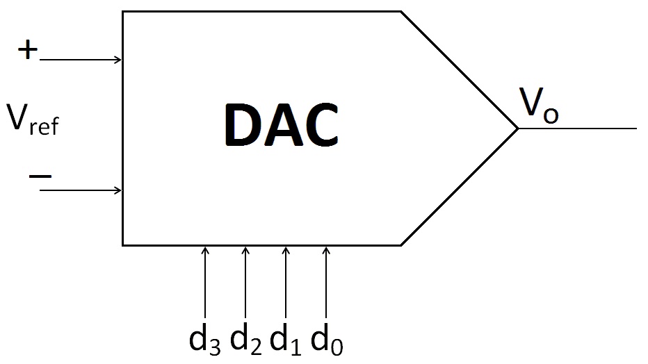
- The following shape is currently supported:
-
flowchart LR id1>ADC] - Perhaps add
id1<ADC]andid[DAC>syntax for support?
-
- For example, the typical shape for an Op Amp:
-
- A rhombus is currently supported:
-
flowchart LR id1{LNA} - So maybe we could add
id1[LNA}andid1{LNA]syntax for supporting triangles?
-
- For example, the typical shapes for MUX and DEMUX:
-
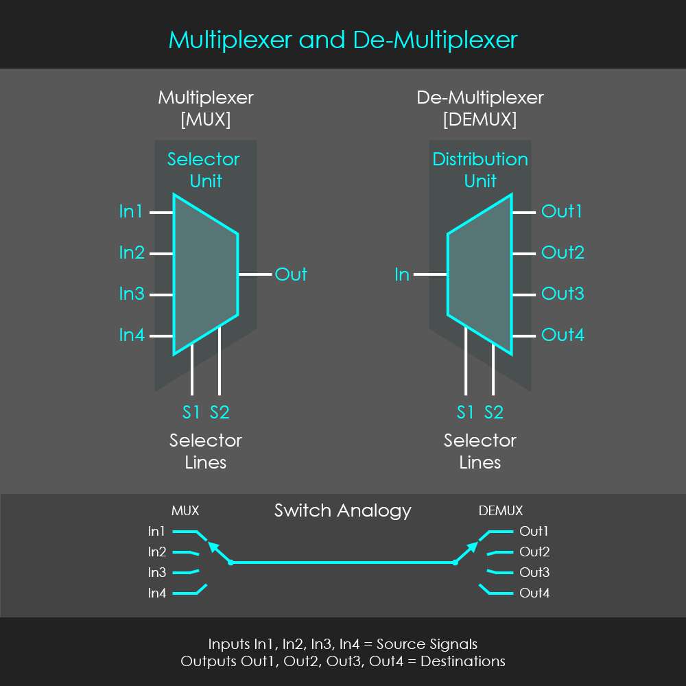
- What is currently supported:
-
    flowchart TD
        A[/Christmas\]
        B[\Go shopping/]
-
- This raises the question of whether we could allow a completely free combination of
[](){}<>, such asid1{xxx>and other such syntax?
- For example, the typical shapes for ADC & DAC:

After completing this step, we can approximately depict some simple Block Diagrams as shown below:

flowchart-elk LR
	a["📡"]:::Trans
	--- LNA{"RF amp"}:::BlackWhite
	-->Mixer1(("`**✕**`")):::BlackWhite
	-->filter["〰\n∿\n〰"]:::BlackWhite_05
	---A1{"IF amp"}:::BlackWhite
	---d["-▶|-"]:::BlackWhite
	---A2{"PA"}:::BlackWhite
	---speaker["🔊"]:::Trans

	osc["∿"]:::BlackWhite_10-->Mixer1

	classDef Trans fill:#ffffff00,stroke-width:0px,font-size:30pt;
	classDef BlackWhite fill:#ffffff00,stroke:#000,stroke-width:2px;
	classDef BlackWhite_05 fill:#ffffff00,stroke:#000,stroke-width:2px,line-height:0.5;
	classDef BlackWhite_10 fill:#ffffff00,stroke:#000,stroke-width:2px,line-height:1.0;
The source code uses a lot of Unicode and some less common features, and it was not easy to draw:
flowchart-elk LR
    a["📡"]:::Trans
    --- LNA{"RF amp"}:::BlackWhite
    -->Mixer1(("`**✕**`")):::BlackWhite
    -->filter["〰\n∿\n〰"]:::BlackWhite_05
    ---A1{"IF amp"}:::BlackWhite
    ---d["-▶|-"]:::BlackWhite
    ---A2{"PA"}:::BlackWhite
    ---speaker["🔊"]:::Trans

    osc["∿"]:::BlackWhite_10-->Mixer1

    classDef Trans fill:#ffffff00,stroke-width:0px,font-size:30pt;
    classDef BlackWhite fill:#ffffff00,stroke:#000,stroke-width:2px;
    classDef BlackWhite_05 fill:#ffffff00,stroke:#000,stroke-width:2px,line-height:0.5;
    classDef BlackWhite_10 fill:#ffffff00,stroke:#000,stroke-width:2px,line-height:1.0;
- The second step is to support more syntax for connecting lines, this step is also of a general nature and not just a requirement of the circuit field:
- For example, arrows pointing to nowhere, and bit numbers on the arrows (to the right of the ADC):
-
- Currently, mermaid does not allow
a-->syntax
- The third step is more challenging, which is specifying the relative position of each node, this has been brought up by many issues and is almost impossible to implement. For example, in the following diagram, both rendering engines mermaid uses cannot render what users expect without enough information:
flowchart-elk LR
    An-->S-->L
    M1-->C1-->AD1
    M2-->C2-->AD2
    subgraph A
        Q-->M1
        Q-->M2
        LO-->Q
        L-->M1
        L-->M2
    end
flowchart LR
    An-->S-->L
    M1-->C1-->AD1
    M2-->C2-->AD2
    subgraph A
        Q-->M1
        Q-->M2
        LO-->Q
        L-->M1
        L-->M2
    end
- The fourth step is specific to the circuit field, supporting various electronic symbols, the difficulty is small, but the workload is large.
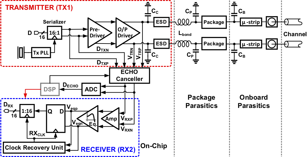
These four steps are just preliminary support for the most basic block diagrams, considering the diversity of circuit levels and the complexity of circuit topologies, to support all circuit diagrams from transistor level to system level is likely to require a huge investment:
| Transistor-level circuits | Analog and mixed-signal circuits | Digital circuits | System-level circuits (Block Diagrams) | System-level architectures |
|---|---|---|---|---|
 |
 |
 |
 |
 |
 |
 |
 |
 |
Projects worth referencing: Lcapy, Schemdraw, d3-hwschematic, SKiDL, netlistsvg, CircuiTikZ, circuit_macros (link2), PySpice
I have been working in puredata a lot lately, and this reminds me of that. maybe a similar approach of not really trying to make seperate shapes, and use text to show what things are would help. I think this + squared-routing would get us readable schematics, even if they were not completely traditional.
Here is a simple example of a sinewave (osc~) connected to output (dac~) with an audio-multiple (*~) for "volume".
It has 2 controls for toggling volume & picking a midi note, but those could be signal refs (which, in puredata are done with receive and send.) All could be signals (similar to "bus" in electronics) like this:
It's a bit of a leaky abstraction in puredata, since it's not really made for it, but here is my shot at the RF thing, above:
With more squared routing, I think it would look pretty decent & readable, even though it doesn't really reproduce the same diagram. I made it by making fake puredata sub-patches for all the things, just to show what I mean. In mermaid, it's already easier:
flowchart TD
    Antenna
    Antenna-->SAW
    SAW-->LNA
    LNA-->M1["Mixer"]
    LNA-->M2["Mixer"]
    M1-->Q["Quadradure Generator"]
    M2-->Q
    Q-->C1["Channel Selection Filter"]
    Q-->C2["Channel Selection Filter"]
    C1-->A1["ADC"]
    C2-->A2["ADC"]
It might be a bit tricky, but if there were a new mode (similar to flowchart TD) that did squared-routing, and knew for example names with R prefix are "resistors", I could see something similar to this actually creating a readable electronic schematic:
schematic
   V["5V"]-->R1["100"] -->|+| D1["LED"] -->|-| GND
flowchart TD
    V["⌁ 5V"]-->R1["100  Ω"] -->|+| D1["→| LED"] -->|-| GND