CNC Knowledge sharing thread
Hi Martin,
First of all, thank you for this wonderful software. I was able install Grbl 1.1J and use OpenCNCPilot to move all 3 axis using manual mode as well as using Keyboard. Just wanted to make sure that I have met pre-requisites (grbl 1.1 and .NetFrameWork 5).
I was also able to utilize "Probe and set Zero" macro to check if my probing is functioning properly. It is working as expected.
I was trying to use the most awesome part of this software, Probing. But "Run" button is not getting enables. What I am missing here? Could you please throw some light on this. Attaching image of my Screen for your reference.
Thanks in Advance.
Regards,
Guru
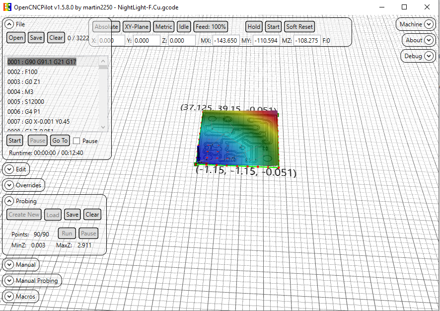
Hi Guru, "Points: 90/90" tells us, that your map is generated already. All 90 points of the map are obviously probed. Next after having done the probing you have to Apply the hight map to your gcode. You find the corresponding button in the "Edit" panel. After having applied the map you can "Start" etching (see "File" panel). Hope that helps.
Harald
Thanks for the reply Harald. It never probed even a single point. As soon as open probe window, select the area to be probed, the attached screen is what I can see. I can't press the Run button. So no probing of even one point. My CNC stays at 0,0,0 x,y,z respectively. I am missing something.
What happens if you click "Clear" in Probing panel? Then "Create new" should be activated.
When clear is clicked, probing area with that 3d effect goes off as expected. When I create new, probing points appears but again the same issue. Run button will be disabled.
Make sure you don’t have the “generate test pattern” box checked and make sure you click on “size from Gcode” once.
-TomH-
On Mar 25, 2020, at 1:08 PM, gururajkashikar [email protected] wrote:
When clear is clicked, probing area with that 3d effect goes off as expected. When I create new, probing points appears but again the same issue. Run button will be disabled.
— You are receiving this because you are subscribed to this thread. Reply to this email directly, view it on GitHub, or unsubscribe.
Where is the "generate test pattern" box? I tried size from gcode. But did not work. Will try this again tomorrow morning. Thanks for the suggestion
On Probing menu click “clear” Click “Create New” Pops up “New Heightmap” window Make sure “Generate Test pattern” box Is NOT selected Click on “Size from gcode” button Click on Ok
“Run” In probing window should be available to click then.
-TomH-
On Mar 25, 2020, at 1:34 PM, gururajkashikar [email protected] wrote:
Where is the "generate test pattern" box? I tried size from gcode. But did not work. Will try this again tomorrow morning. Thanks for the suggestion
— You are receiving this because you commented. Reply to this email directly, view it on GitHub, or unsubscribe.
Hi tarmon01,
You were right. "Generate Test pattern" was checked because of which "Run" button was not enabled. Now I was able to probe and mill a sample PCB. Attaching the image of the milled PCB if anyone is interested,
Looks like engraving bit was slightly broken and went bit deeper. I'll try with a new bit. Also I had set the milling depth as 0.6mm in my Gcode. Looks like that can be reduced too.
Also one thing I observed. My's CNC Z was not raising up quite high when it is not suppose to mill. Because of this engraving bit went over some of the circuit track and isolated it. Will need to work on this. Any suggestion on the depth of milling and height of the end mill will be helpful.
Thanks for all the help.
Regards,
Guru

Hi Guru!
If you use the same bit for probing and for milling (without changing anything at the bit inbetween probing and milling), you don't have to zero Z before probing.
But I take it as good practice to zero Z before starting the probing process.
Concerning the depth, I use 0.08 mm (80µm) to go through the 35µ copper cladding. In theory 0.04µ should be enough, but we deduced the distance the router needs to stop after recognizing the touch event as reason why we need to set the milling depth deeper than that.
Concerning the trenches you milled I propose, you should parametrize some more routes to widen the trenches. I use EAGLE as design tool. There exists an ULP named pcb-gcode.ulp which generates the routing pathes around the traces. This ULP allowes to define the number of additional rounds the bit should do to widen the trench between trace and remaining copper. This at least eases the soldering process (no or at least less chances to make a short).
Hope that helps... Harald
Hi Harald,
Thanks for your time to update these findings. I am using same bit for probing and milling. I was afraid of breaking the V shaped bit if I don't zero Z. Some time when there are error, we hit soft reset and then press Zero machine, I have got couple of V bits broken due to crashing of my machine. Now, back to update about my findings. My Z was not travelling as expected. When I try to move Z by 10mm, it was just moving only 2 mm. I had recalculate step/mm and now its working fine.
Now I think 0.08mm as you said Harald, would be sufficient to engrave the copper clad.. BTW, I was able to drill my PCB. In some place drill bit (0.7mm) did not go all the way down. In most places it did.
Do we need to do the probing and applying hight map to your drill gcode also? Current PCB looks as attached below. Not very accurate though. But good to go as of now.

BTW, the actual issue I mentioned here, was not an issue. It was lack of my knowledge about this tool. So all other things are general discussion. Please suggest me if its ok to discuss these general thing here or should I close this issue?
Hi Guru, since I am not sure about the squareness of my router I apply the heightmap also to my drill code. This is convenient if you specify the drill depth so that the board is just drilled through (I use 1,7 mm as drill depth. Together with the double sided adhesive tape I fix my boards with, this gets through and doesn't touch the waste plate (don't know the exact wording for the plate beneath the work piece which prevents the bit to touch the routers surface). If you don't care about the waste plate, you can specifiy the drill depth deeper. In this case you don't need to apply the heightmap to the drill code. The same applies to the milling if you use your router to cut out the finished board.
Concerning your findings about the wrong step/mm on Z, I suggest you should check those parameters for all three axes. You can adjust this in the GRBL settings.
Harald
Hey Harald,
I normally use a thick double sided tape to stick the copper clad sheet to my waste wood board and then place the wood on my CNC bed. There will be a gap of around 1 to 2 mm between copper clad and the wood board itself. Hence my drill bit goes all the way down but does not touch the waste wood board.
I had found X and Y's steps/mm value and it was accurate. Only Z was missing. Now all three are perfect.
One more update :( I lost a 0.7mm router bit today morning when I was trying to cut the board to required size using my CNC. This was because after milling, I could not do the probing. Lesson learnt:
- Do probing for all three gcode file i.e 1) Milling (2) Drilling (3) Cutting.
- Apply the height map to respective Gcode files and save it.
- Then start milling.
Any other suggestion for milling, drilling and cutting would be appreciated.
Thanks and Regards, Guru
Hi Guru,
I formerly used that thick tape, too, but found, that using thinner double sided tape results in drastically better results. The thicker version is named "Spiegel-Klebeband" over here in Germany, the thinner version is called "Teppich-Klebeband".
The reason seems tob e, that when probing, the bit stops exactly when it touches the surface. When milling, it implies some force to the board and this thicker tape lets the board give way.
Not sure whether I got you right, but you surely have to probe only once. You can apply this one time probing to all three files, one after the other.
Harald
A tip.
If you “save” the heightmap file you can “load” It if something goes wrong ( closing opencncpilot by mistake for instance) and then you can apply it to drill/mills on a partially done board when the program is running again. There is also a setting box in the config menu that saves the heightmap file automatically.
-TomH-
On Mar 27, 2020, at 7:39 AM, deHarro [email protected] wrote:
This is the correct one This is the wrong version
Harald
— You are receiving this because you commented. Reply to this email directly, view it on GitHub, or unsubscribe.
Great tips here. Harald: I'll try tomorrow with thinner tape. I was under assumption that each of the gcode file will have its own height map. Your explanation clarifies that same height map can be used for all three is satisfactory. I'll try it out.
tarmon01 : Very nice to know these option exists. I'll give it a shot tomorrow.
Thanks for all this suggestion.
Hi Guru,
It if something goes wrong ( closing opencncpilot by mistake for instance) and then you can apply it to drill/mills on a partially done board when the program is running again.
In this case you must carefully zero Z (and obviously X and Y as well ;) again, preferably at the same location as you did it first.
Harald
Hi Guru,
same height map can be used for all three
Since OCP has no option to avoid probing at already etched places, the possibility to just aim at such areas when probing an already treated board is very likely. So it's sort of mandatory to only probe once.
Harald
Yeah Got it Harald. Another thing what I follow is, First time I zero all three axis, I store that Machine position using G28.1. Later any time I want to restart, I raise the Z to safe height (like 10mm) and issue command G28 to come back to initial zeroed position. From there on I start all over again.
BTW do you use a different Bit for Engraving and Cutting the board? I saw a video where V shaped bit itself was used to mill and cut the copper clad sheet. I tried with router bit and broke it. The router went deep and stuck there while CNC moved ahead to break the bit..
Hi Guru, the V-bit must only be used for etching and for spot drill (marking) the holes (spot drill: just touch the surface of the copper clad to mark the position where the cylindrical drill bit then should make the hole).
For milling the board outline I use 1,4 mm (sometimes 1,0 mm) "diamond toothed" or "spiral-toothed" drill bits. The holes are drilled with 0,8 mm or 0,9 mm "diamond toothed" drill bits.
Harald
Hi Harald and tarmon01,
I create another PCB today. Had a different experience. I used 0.08 as the depth for PCB milling/Etching. My probing started from Bottom Left of the board, went horizontally i.e. left to right, then 5mm up right to left so on till it reached Top Right. (Attaching the image to make this clear)

After applying height map, when I engraved the board, I saw that the bit went deeper towards the left of the board, but just touched the board on the right side.
My question to you : Is it need that we need to get probing some how from bottom to top as shown in the video of this website (instead of bottom left to right) to get correct probing height. For earlier board, probing was done from bottom to top as in the video. So I have this doubt.
- Though I used 0.08mm as the depth, looks like it went deeper on left side of the board. Is this problem due to above question.
Image attached in case you want to see it. Tracks are too thick...

Gururaj
Gururaj,
I don’t think it matters where it starts. Martin would know for sure.
I did once do a heightmap, realized I forgot something that grew the board size and did not do a new heightmap, because I already did one, 🧐and the traces looked great until it suddenly they stopped etching correctly when they hit the edge of the heightmap. A learning experience.
I always start my projects in the center of the board. I also go quite a bit deeper with my bit 0.19mm. This for me always seems to work. But I use a 60 degree carbide etching bit. And I am mostly doing 30mil traces which isn’t very fine.
https://www.amazon.com/3-175mm-Engraving-EnPoint-Carbide-Aluminum/dp/B019K5G6AI
I gave up on the really really cheap 30 degree-ish bits as the very tip always seemed to break even if I slowed down the mill down to deathly slow speed.
But the other folks here have had better luck with those bits and could advise better.
Thanks,
-TomH-
On Mar 28, 2020, at 12:11 PM, gururajkashikar [email protected] wrote:
Hi Harald and tarmon01, I create another PCB today. Had a different experience. I used 0.08 as the depth for PCB milling/Etching. My probing started from Bottom Left of the board, went horizontally i.e. left to right, then 5mm up right to left so on till it reached Top Right. (Attaching the image to make this clear)
After applying height map, when I engraved the board, I saw that the bit went deeper towards the left of the board, but just touched the board on the right side.
My question to you : Is it need that we need to get probing some how from bottom to top as shown in the video of this website (instead of bottom left to right) to get correct probing height. For earlier board, probing was done from bottom to top as in the video. So I have this doubt.
Though I used 0.08mm as the depth, looks like it went deeper on left side of the board. Is this problem due to above question. Gururaj
— You are receiving this because you commented. Reply to this email directly, view it on GitHub, or unsubscribe.
Thanks for the update torman01. I think I need to buy 60 deg bits like you have suggested. What do you use for cutting board to its correct measurement.? Can you please share some pics of boards and your CNC machine. Btw can I know your real name.
My name is Tom😃.
I have designed & built my “Mini-chine “ to use 4 tools without changing bits; A pcb carver bit, A .9mm drill, cutout tool( 2mm but I may change it to 1mm), and a pen plotter. It’s based on several parts of the standard Chinese kits but I’ve had to make several aluminum pieces on my big CNC “Chine” machine. I use a decent spindle for the traces and 2 cheap spindles for drilling/cutout as those 2 functions don’t require the same precision.
Martin has modified openCNCpilot such that it will allow me to pass addition gcodes through so I can make a whole board in one gcode file( but I haven’t tested his changes yet). I do not use double sided tape but I do have a backing board that makes contact to the circuit board with clipboard clamps. I use .19mm for traces and 1.9mm depth for cutting/drilling.
It is not perfect yet.. the x axis has too much backlash that I need to fix. But it is good enough for the moment until I can get around to fixing it. I am also in the process of designing a single Arduino shield instead of the several little boards shown in the pictures above, that work with the controller that came with the kits.
Some things that may help you. These are meant as a helpful comments. Your machine has too much backlash in it, going by the picture you sent. Circles should circles not ovals. Also the alignment of drills to the etching are not centered. Anti- backlash nuts would help assuming you don’t have them on ? If you do have them on, make sure the spring is fully compressed and not loose when you screw them on. Also use precise right angles to ensure that X,Y,and Z are perpendicular although X & Y are less important for you than me as you use doubled sided tape to hold the board on and that is likely not going to be very square. Make sure whatever structure you are using is as stiff/rigid as you can make it. if it wobbles or deforms. That’s not good.. add supports as needed so it does’t move when you push on the moving parts by hand. ( or at least minimize it)
Hopes this helps!
FYI. If you are interested in other things I do, my website is TnRCrafts.com.
Thanks,
-TomH-
On Mar 28, 2020, at 3:13 PM, gururajkashikar [email protected] wrote:
Thanks for the update torman01. I think I need to buy 60 deg bits like you have suggested. What do you use for cutting board to its correct measurement.? Can you please share some pics of boards and your CNC machine. Btw can I know your real name.
— You are receiving this because you commented. Reply to this email directly, view it on GitHub, or unsubscribe.


Hi Tom, Thank you so much. Your machine is impressive. I never thought we can have multiple spindle on a single machine. Looks awesome.
The PCB quality is also excellent.
Regarding my CNC machine, it's home made machine with V slot aluminium profile, v wheels and movement is through timing belt. See the image below.
 I'll surely work on your comment. Since I don't have threaded road and nut for X and Y axis, I need to check how to avoid Anti-backlash. The CNC as whole doesn't shake or wobbles. But moves easily by hand. I need to work on that as well.
Regarding electronics, I have arduino nano on grbl CNC shield v4. One single board with stepper controller on it. Lot of work to do before I get PCB like yours. Thanks for you inputs. It matters a lot at this time
Regards, Guru
Hi everybody,
just to chime in and answer a few of the questions:
OpenCNCPilot always chooses the closest point to the current position for probing. This means that the probing pattern can be different from time to time. Assuming your machine doesn't loose steps, different probing orders don't make a difference. If the milling depth varies from side to side, it's always an issue with rigidity, either in the machine or the board. I only recommend tape (over the entire board surface, not just small pieces) to hold down boards, and I'm actually quite surprised that Tom's boards come out that cleanly with just two clamps.
Regarding backlash in your machine: timing belts can be quite good in that regard. My first machine, a Shapeoko 2, also used V-rails and timing belts. The best I could do were 0.4mm traces and 0.8mm pitch SMD components. There are a few catches though:
- The rolling resistance of your bearings must be very low. Try disconnecting the motors and adjusting the rollers until XY moves with little to no resistance.
- The belts mustn't be too cold. My boards turned out worse in winter, even with the machine sitting in my bedroom.
- Belts tend to 'remember' their shape, so after sitting around for a while, there will be a 'bump' when moving over the resting place. My solution was to un-tension the belts when the machine was not in use.
- The belts must be tensioned properly of course.
@tarmon01 impressive setup! How do you manage the multiple Z axes with grbl?
Martin
Guru,
Pretty cool to create what you did! I like the innovation you used on the slides.
The belts work best for a laser engraver which has little resisting force when it moves in x and y directions. A spindle requires a very rigid structure as you don’t want the spindle to tilt in opposition to the direction it is going. Pretty sure that explains the results you are getting.
So if you can get lead screws for x and y, that’s probably the best way to go. If you can’t then using some pulleys and steel wire to Implement something called a “moving knot” in x and y can help to prevent “racking” which is what it is called it when the structure goes out of square ( which it does when carving)
Here is a great site for help and to see others peoples design if you have seen it already
tps://www.cnczone.com/forums/diy-cnc-router-table-machines/
Here’s some info on the “moving knot”
https://m.youtube.com/watch?v=V_RsIIGw0xk
https://www.cnczone.com/forums/diy-cnc-router-table-machines/51485-make-gantry-rock-solid.html
Thanks,
-TomH-
On Mar 28, 2020, at 9:58 PM, gururajkashikar [email protected] wrote:
Hi Tom, Thank you so much. Your machine is impressive. I never thought we can have multiple spindle on a single machine. Looks awesome.
The PCB quality is also excellent.
Regarding my CNC machine, it's home made machine with V slot aluminium profile, v wheels and movement is through timing belt. See the image below.
I'll surely work on your comment. Since I don't have threaded road and nut for X and Y axis, I need to check how to avoid Anti-backlash. The CNC as whole doesn't shake or wobbles. But moves easily by hand. I need to work on that as well.
Regarding electronics, I have arduino nano on grbl CNC shield v4. One single board with stepper controller on it. Lot of work to do before I get PCB like yours. Thanks for you inputs. It matters a lot at this time
Regards, Guru
— You are receiving this because you commented. Reply to this email directly, view it on GitHub, or unsubscribe.
Martin,
There are 4 hold downs. Two clipboard clamps, and two thumbscrews that hold aluminum pieces that overlap the board edges. I One clipboard provides electrical contact for the board probing. The clipboards are spaced apart for the inexpensive copper clad boards to slide between on Amazon.( a little over 100mm I think).
What Grbl doesn’t know about, It can’t complain about< heh>.
Grbl however does support 2 coolant controls as well as work offsets. Which is enough to drive 4 different tools with the proper circuitry and Gcode mods.
If you used belts perhaps Guru can also, I’ll leave that in your capable hands.
Thanks,
-TomH-
On Mar 29, 2020, at 5:20 AM, Martin Pittermann [email protected] wrote:
Hi everybody,
just to chime in and answer a few of the questions:
OpenCNCPilot always chooses the closest point to the current position for probing. This means that the probing pattern can be different from time to time. Assuming your machine doesn't loose steps, different probing orders don't make a difference. If the milling depth varies from side to side, it's always an issue with rigidity, either in the machine or the board. I only recommend tape (over the entire board surface, not just small pieces) to hold down boards, and I'm actually quite surprised that Tom's boards come out that cleanly with just two clamps.
Regarding backlash in your machine: timing belts can be quite good in that regard. My first machine, a Shapeoko 2, also used V-rails and timing belts. The best I could do were 0.4mm traces and 0.8mm pitch SMD components. There are a few catches though:
The rolling resistance of your bearings must be very low. Try disconnecting the motors and adjusting the rollers until XY moves with little to no resistance. The belts mustn't be too cold. My boards turned out worse in winter, even with the machine sitting in my bedroom. Belts tend to 'remember' their shape, so after sitting around for a while, there will be a 'bump' when moving over the resting place. My solution was to un-tension the belts when the machine was not in use. The belts must be tensioned properly of course. @tarmon01 impressive setup! How do you manage the multiple Z axes with grbl?
Martin
— You are receiving this because you were mentioned. Reply to this email directly, view it on GitHub, or unsubscribe.