UART mode on Arduino
Hello,
I'm using an Arduino Mega Pro 2560 and a TMC2209 V2.0 from Makerbase. This one : https://aliexpress.com/i/33043140087.html I uploaded the sketch below and my Serial monitor outputs this error continuously: "Stepper driver not setup and communicating!"
#include <Arduino.h>
#include <TMC2209.h>

HardwareSerial & serial_stream = Serial3;

const long SERIAL_BAUD_RATE = 115200;
const int DELAY = 200;
const uint8_t RUN_CURRENT_PERCENT = 40;
const int32_t VELOCITY = 20000;
const uint8_t STALL_GUARD_THRESHOLD = 50;

// Instantiate TMC2209
TMC2209 stepper_driver;

void setup()
{
  Serial.begin(SERIAL_BAUD_RATE);

  stepper_driver.setup(serial_stream);

  if (stepper_driver.isSetupAndCommunicating())
  {
    Serial.println("Stepper driver setup and communicating!");
    Serial.println("");
  }
  else
  {
    Serial.println("Stepper driver not setup and communicating!");
    return;
  }

  stepper_driver.setRunCurrent(RUN_CURRENT_PERCENT);
  stepper_driver.setStallGuardThreshold(STALL_GUARD_THRESHOLD);
  stepper_driver.enable();
  stepper_driver.moveAtVelocity(VELOCITY);
}

void loop()
{
  if (not stepper_driver.isSetupAndCommunicating())
  {
    Serial.println("Stepper driver not setup and communicating!");
    return;
  }

  Serial.print("run_current_percent = ");
  Serial.println(RUN_CURRENT_PERCENT);

  Serial.print("stall_guard_threshold = ");
  Serial.println(STALL_GUARD_THRESHOLD);

  uint16_t stall_guard_result = stepper_driver.getStallGuardResult();
  Serial.print("stall_guard_result = ");
  Serial.println(stall_guard_result);

  Serial.println("");
  delay(DELAY);
}
Library is : https://github.com/janelia-arduino/TMC2209
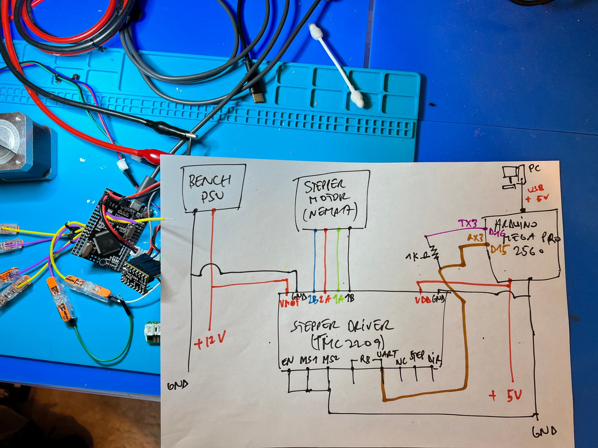
Here is my wiring: Mega is powered with 5V from my PC's USB port. I make a 5V/GND rail from the 5V output of the Mega. That 5V rail powers the TMC2209, via the VDD pin EN pin of the TMC is connected to GND 1B/1A/2A/2B on the TMC are connected to a NEMA17 GND and VMOT on the TMC are connected to 12V from my bench PSU. Pin labelled "UART" on the TMC is connected to pin D15 of the Mega (which is Serial3, so I modify the sketch accordingly) Pin D16 is connected, through a 1K resistor, to D15. (as per the datasheet, this is "one wire" uart apparently...)
What am I missing? I tried with other hardware serials (Serial1 and Serial2) without any success. I tried switching RX/TX pins, maybe, for each hardware serials, without any success. I tried with an other TMC chip, without any success (I have 5 of those). I tried pulling both MS1 and MS2 to GND. Tried one up to 5V an one GND (and vice versa) to mess with the serial address (0b00 by default), without any success.
I am out of clues now. Thank you.
@tomasAl Yes. If you stick to my drawing you should be OK. My schematic was fine but the way I plugged that 1k resistor between TX3 and RX3 was potatoe. See https://github.com/janelia-arduino/TMC2209/issues/11