Automatic-Plant-Watering-System
 Automatic-Plant-Watering-System copied to clipboard
🌱 Urban Self Sustaining Windowsill Planter
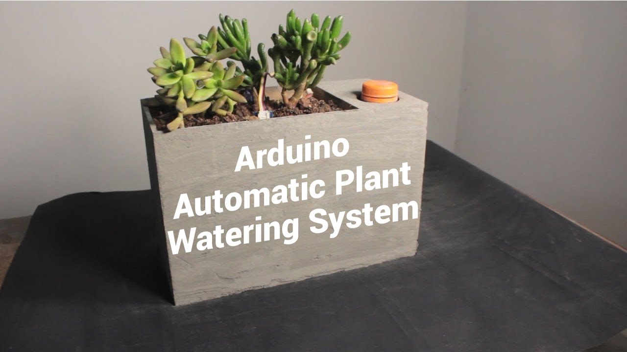
Automatic Plant Watering System using Arduino
Meet Sprouter - the Modern Indoor Planter which automatically waters your plants, herbs, vegetables, etc and will revolutionize your gardening game.
Full Video:
It consists of an integrated water reservoir from which water is pumped & keeps the plant's soil hydrated.
A soil moisture sensor is calibrated such that it periodically measures the moisture of the soil thereby regulating the water flow. If the soil is too dry, the water pump automatically switches ON and goes OFF when the soil moisture has reached the desired level.
If you're the person who underwaters their plants, Sprouter will ensure you will never have to worry about being a bad gardener again. And if you're the sort of person who overwaters their plants to compensate for absenteeism, it means your not in danger of drowning your plants or seeds.
Sprouter's water reservoir capacity is around 500 ml / 17 fl oz, which allows you to neglect your plants for as long as a month before it needs a refill.

The optional Bluetooth feature can be used to manually toggle & control the water pump wirelessly from your smartphone.
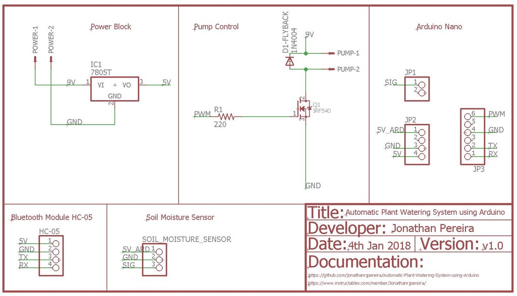
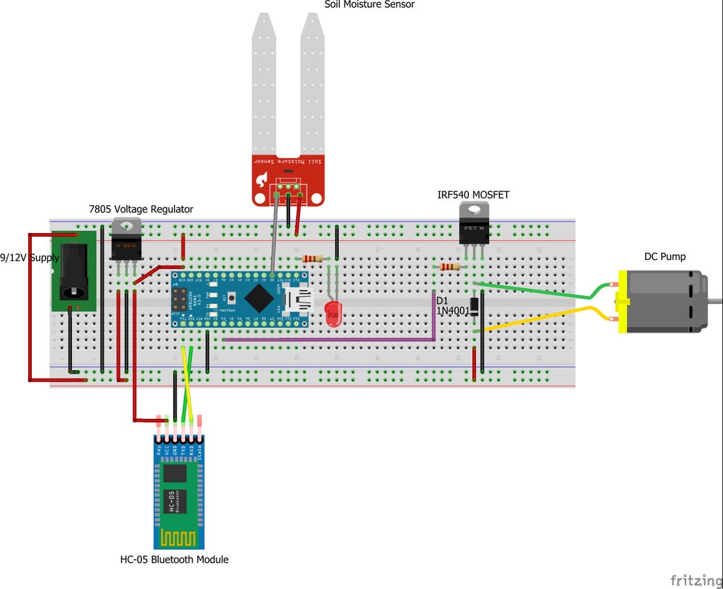
Electronic Design
Electronic Components List:-
Arduino Nano: AliExpress
DC Water Pump: AliExpress
Soil Moisture Sensor: AliExpress
HC-05 Bluetooth Module: AliExpress
LM7805 Voltage Regulator: AliExpress
IRF540 MOSFET: AliExpress
220 Ohm Resistor: AliExpress
IN4001 Diode: AliExpress
Header Pin Strips: AliExpress
DC Barrel Jack: AliExpress
Screw Terminal Block: AliExpress
PCB: AliExpress
AC-12VDC Adapter: AliExpress
Tools:-
Soldering Iron: AliExpress
Solder Wire: AliExpress
Power Block: The 7805 regulates the supply voltage and reduces it to a constant 5V making it suitable to run the Arduino & Soil Moisture Sensor.
Pump Control: The MOSFET acts as a switch which is controlled by the Arduino. We use the MOSFET since the Arduino cannot directly power the DC Pump. The resistor connected to the gate of the MOSFET prevents the MOSFET from getting damaged. The flyback diode connected across the pump provides a path for dissipation of stored energy when the pump is switched off. The Anode of the Diode is connected to the Drain of the MOSFET. The Cathode of the Diode is connected to the 9V supply rail. The Source of the Diode is connected to GND.
Moisture Sensor: The sensor feeds an analog value to the Arduino. The threshold level of moisture is calibrated by the user depending on the type of plant used.
Bluetooth Module: Uses Serial Communication to transfer data between the Arduino and your Smartphone.
Electronic Assembly
 A 1x Scale printable PCB as well as the board view and schematic is available in the GitHub repository.
The repository also contains an A4 size PDF which contains multiple PCB's on a single page. This can be used to make multiple PCB's at a time for mass production
Software & Bluetooth Configuration
Software: The Moisture Sensor is connected to an Analog Input pin of the Arduino. A threshold value determines whether the Pump should be ON/OFF. You can find the code at Sprouter: GitHub/Code Feel free to modify & contribute to the GitHub repository.
Smartphone App & Bluetooth Configuration: The HC-05 Bluetooth module is the intermediate block between the Smartphone & Arduino. It uses Serial Communication to send data from the Smartphone to the Arduino & acts as a Remote Control.
The app transmits the value '48' or '49' which represent 'ON' & 'OFF' respectively. The pump can hence be controlled wirelessly.


Simply open the app, scan for discoverable devices & pair with the HC-05 module. then click on 'Switch Mode' and toggle the onscreen button. The app is available at Bluetooth App
Mechanical Design

The main body of Sprouter is a 30cm X 15cm X 19cm Box made out of MDF.
All Mechanical Design steps have been clearly demonstrated in the video attached at the start of the Instructable. You can also check it out at Sprout: Video/Mechanical Design
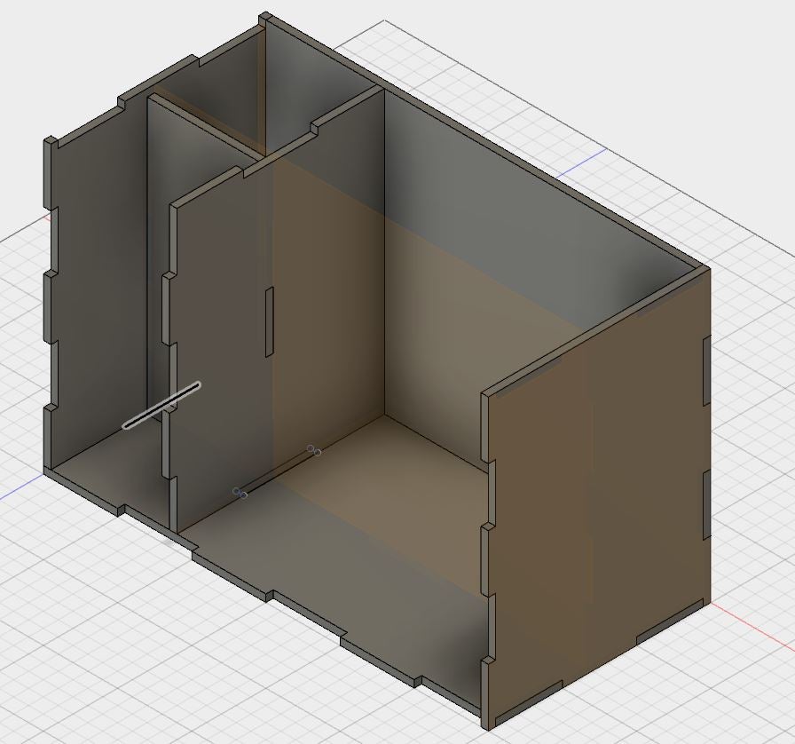
The box is divided into two sections:
- The larger section contains the Soil & Plants
- The smaller section is further divided into two more sections such that one section contains the Circuit Board while the other contains the Water Reservoir.
The water reservoir is a 500ml plastic bottle.


The MDF box has 8 separate interlocking faces which can be laser cut and slotted into each other.
The Laser Cutting files, Fusion 360 Design file (3D Design file), isometric as well as orthogonal views of each face can be found at Sprout: GitHub/Mechanical Design
You can also find editable Illustrator files in the GitHub repository which can be modified to your specific requirements/dimensions and then can be laser cut.
Mechanical Assembly: Bottle Preparation


The water reservoir is a 500ml plastic bottle. A typical 500ml plastic Soda bottle can be used for this.
The maximum diameter of the bottle should be 74mm. The maximum diameter of the cap of the bottle should be 50mm. The maximum height from the base of the bottle to the lowest part of the cap should be 18.5 cm.
The bottle must be cut about 50mm above its base so that the pump can be placed within it. Holes must be cut into the bottle such that the Outlet Pipe and Power wires can be fed through the bottle.

Once the Outlet Pipe and wires have been taken out through their respective holes, the bottle can be sealed again. To seal the bottle we must use an Epoxy Compound which will harden within a few hours. This will prevent any water from leaking out.
The water can be refilled from the top of the bottle by simply opening its cap.
Mechanical Assembly: Box Preparation
Once you have successfully laser cut the 8 different faces of the box, Apply several coats of a high-quality wood varnish to each side of each face.This makes it highly water repellant & makes it resistant to moisture & humidity.
Mount the Power Jack on the Back Plate too & connect it to the Circuit Board.

Mount the Circuit Board on the Back Plate of the Box such that it fits within their respective section.
Pull the Pump Outlet Pipe through the given holes such that it reaches the Plant soil section. Do the same for the Moisture Sensor wires.
Don't forget to connect the Water Pump to the Circuit Board as shown in the Schematic
Begin interlocking the different faces of the Box and ensure that bottle fits snuggly into its designated area.
Apply wood glue or an adhesive to seal the entire box.
Mechanical Assembly: Cement Finish


This step will determine the out texture & final finish of the box as well as give the planter another protective coating.
Apply glue to each face of the box. Then sprinkle some cement over the glue. Use the remaining circular MDF piece which was cut from the Top Plate to smoothen the cement across the surface of each face of the box. Repeat this step for each face of the box as demonstrated in the video.
Once the cement dries, sprinkle with water every 6 hours for 1 day. This will allow the cement to cure, with no cracks and will also prevent water from leaking.
Add the Soil & Plants

Once the cement has cured, fill the box with soil.
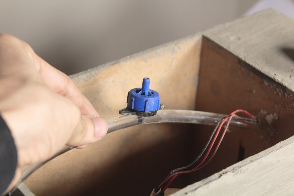
Remember to heat seal the end of the Outlet pipe before making a hole in it for the dripper. The dripper is used to regulate the water coming out of the pipe so that the water does not flow out of the planter.
Place the Soil Moisture Sensor inside the soil.
Power Sprouter through the Power Jack at the Back Plate & make sure fill the water reservoir to the full level.
Test whether everything works and you should be done.
Contributing
Are you a programmer, engineer or designer who has a great idea for a new feature/design in Sprouter? Maybe you're just a beginner or you've spotted a bug? Feel free to grab our code, schematics, 3D design files & laser cutting files from Github and tinker with it.
Metadata
Owner
Metadata
🌱 Urban Self Sustaining Windowsill Planter