WiFi-remote-for-Bestway-Lay-Z-SPA
 WiFi-remote-for-Bestway-Lay-Z-SPA copied to clipboard
esp32
I havent hacked my pump but I got the wrong esp8266 lol (slightly smaller one) so I though I could try to port the code to esp32...
any other design decision I should consider while tinkering with this? (ill probably take few weeks)
I've been thinking of adding optional low-pass filters* on the data lines but since I don't need them myself I haven't done it yet. *serial resistor and a cap to gnd.
Also it would be nice if it were pin compatible with earlier versions. It means crazy wiring on the pcb though. Alternatively the code must be easily configurable.
what are the filters for? maybe I need them? (I am still waiting for aliexpress stuff :( )
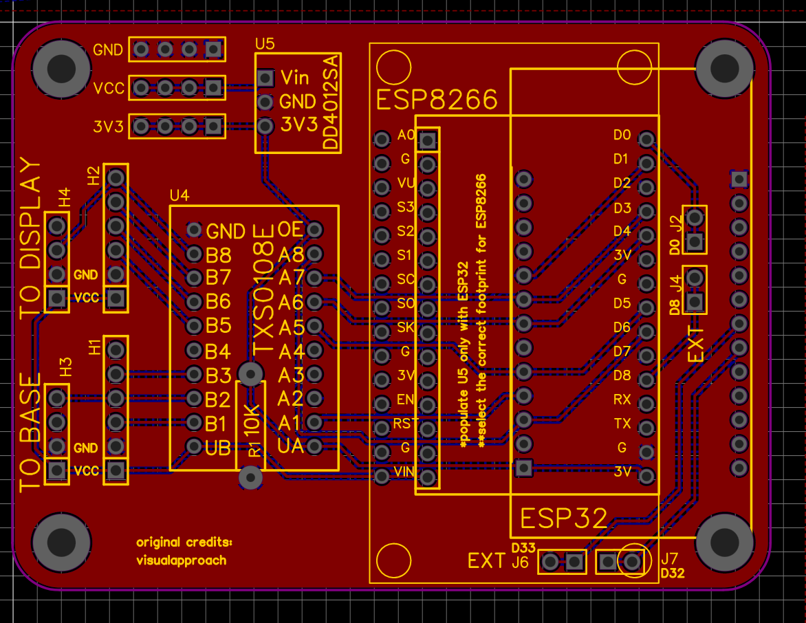
and yes, is fully compatible with the early version, I just added another footprint for the tiny esp8266 board and the other one will just need a mapping of the pins for the esp32. And ofc the extension ports, but depending on the board you are using you cover the EXT you dont need :D
what are the filters for? maybe I need them? (I am still waiting for aliexpress stuff :( )
2021 models and maybe some 4 wire models need them. There are some info in the build instructions and several threads in the issues and discussions forum about it.
Also it would be nice if it were pin compatible with earlier versions. It means crazy wiring on the pcb though. Alternatively the code must be easily configurable.
Hey! I like the new pcb 😹 any reason for changing the pins?
Because I asked you to not do that 😂! I was actually going to tell you that I broke that rule. But wanted to test it first. I think it's a better board considering both parallel wires and a whole ground plane. Not to mention the previous board is super confusing to work with. Function parameters was not in the same order as the pins even. But new pcb remains to be verified. And I don't consider it to make your pcb redundant. Please continue your work and I'll put it up as an alternative for those who need those extra pins on the 32. Obviously you may as well scrap the original pin out if you want. I've already prepared the code for that. And feel free to copy or improve the lp filters.
Ahh I see xD was it because pins where shared between the 4 and 6 pins?
The 4CH board works so well that I dont think it needs any filter for my setup, but I would love the esp32 which I feel more stable for wpa2 wifis. A printed holder box (that is why the screw holes are at specific distance 5 and 7 cm) would be ideal but all is on thinking process still so there is time to relayout the pins if I ever transition. The code being duplicated for the two versions and with many hardcoded things for the 8266 is quite a lot of work to port tho so that was the first obstacle and appreciation of your code which works awesome in my spabad
Ahh I see xD was it because pins where shared between the 4 and 6 pins?
More like: hey this experimental rats nest works so don't mess with it.
The 4CH board works so well that I dont think it needs any filter for my setup...
The intention of my new pcb is to use the left headers if you don't need the filters, and the right ones if you do. No need to mess with bridging the resistor slots. And to use the same headers for 6w and 4w. Just leave to holes empty for the 4w.
The code being duplicated for the two versions and with many hardcoded things for the 8266 is quite a lot of work to port tho so that was the first obstacle and appreciation of your code which works awesome in my spabad
Thanks. I think the 4w should be easier to port. We rely on the softserial lib which I assume works on the esp32. The reason I hardcoded the gpio ports for 6w was that digitalread/write/mode wasn't working in interrupt service routines. It may work after the newest esp8266/32 core lib updates. But the edge triggered interrupts may not work on all 32-chips since it's a hardware bug allegedly. So must use high/low instead of rise/fall.