gbs-control
 gbs-control copied to clipboard
Scanlines while using bob deinterlace
Not sure if this was brought up before or not, but when you input 480i signal, while scanlines and bob deinterlace are both on, scanlines doesnt seem to turn off automaticly, creating an image with changing black lines on every frame on odd and even lines This however doesn't happen while using motion-adaptive deinterlacing, picture is shown without any lines Maybe a small amount of code can be added to turn scanlines off when detecting 480i input?
That's actually intended. It mimics the look of some CRTs with their scanlines also alternating like that.
Hm, very interesting, never saw such screens since my experience comes to default SD tubes where 480i is shown without alternating scanlines
If thats the case with this feature, and and this is not desirable to remove it in the main code, maybe I can add some code on my downloaded file to turn off scanlines on 480i input, without making adjustments to main code located here on github. Any advise on that?
So you want to keep scanlines on 240p input, but dynamically turn them off on 480i?
Try commenting out this line:
https://github.com/ramapcsx2/gbs-control/blob/master/gbs-control.ino#L6192
Sorry for not answering earlier. I had tried commenting out the line, but it seems that it doesn't work, I still get lines in interlaced mode. I had some more experiments while using this board on 640x480 output on 240p signal input, it seems that scanlines doesn't block all the colors on even lines when using scanlines on highest strength (I only tested this on crt vga monitor that I have, not sure how it behaves on flat screens) For example: white and yellow color have blank scanline, while red have more dimmed red scanline, and blue almost repeats color all together Not only that, but on the 240p test suite on snes, in the test of vertical scrolling on the slowest speed it seems that even lines copies odd lines and not drawing scanlines at all. This behavior repeats on all the signals when it displays fast moving image or sprite that goes up or down very fast. For the time, I want to try and bypass scalers scanline feature all together, and install a scanline generator, my idea behind it to turn it off when gbs receives 480i input, and turn on on 240p input. The idea to automate this process is to send a logic high to one of the wemos board pins when the scaler receiver interlaced video signal and send logic low if scaler receives progressive video signal, this way I can power on or off my scanline generator by using, for example, a MOSFET or optocoupler. So the question now is: is it possible to use one of the controller boards pins to output logic signal depending on what signal the scaler is currently receiving (progressive/interlaced)? If so, what function in the code can detect the type of signal?
The scanline "strength" is a neat side effect of abusing one of the chip features.
I know that it barely blends blue, for example. It is an overall pleasing effect this way (to me at least), but yeah, it can't really produce entirely black scanlines.
If you want to do an external scanline circuit, you'll have to find one free output pin on the ESP8266 (should be one or two left somewhere).
You can then switch that pin in the places where I now toggle the internal scanliner.
You'll have to develop it yourself, but I'll help with specific questions :)
After some tinkering with the code i realised that i have no idea where to search for detection of progressive and interlaced mode to make a logic output on the ESP8266 out of it :)
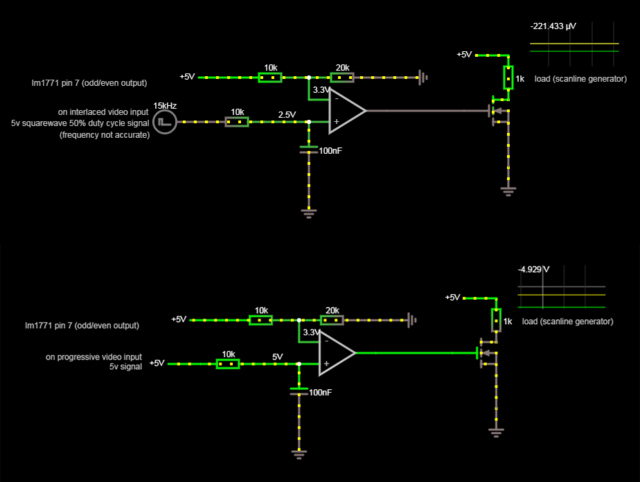
So i decided to take a hardware approach, since i using lm1881 sync stripper it has a neat function of outputting signal on odd and even lines, essentually giving a 5v square wave on interlaced video input and solid 5v on progressive. So by building a filter to make a 2.5 volt output on interlaced and 5 volt on progressive we can use comparator circuit to turn on our scanline generator.
Here is the sketch of a circuit that i made in circuit simulator online: http://tinyurl.com/y7rw4kcq
And here is a picture of said circuit in two operation modes, the 1k resistor near MOSFET imitates the load of scanline generator
Well, whatever you build, don't put +5V on any of the GBS signals.
If you use your odd/even detect to control another circuit for the scanlines, then remember that it'll only work for truly interlaced sources.
240p stuff doesn't have odd/even fields ;)
hello, is it possible to get scanlines on 480i/p like the ossc can? as i read scanlines are only possible in 240p thanks