open-source-rover
 open-source-rover copied to clipboard
[Bug Report] PCB Assembly Readme.md: Controller Board's JST connector needs to be connected backwards
The opening in the pins on the JST connector should face OUTWARD as shown below.

https://github.com/nasa-jpl/open-source-rover/tree/master/electrical/pcb_assembly#362-solder-40-position-headers-2
Just to clarify, this ticket is to point out that the connector should have been designed to be put on 180 degrees from what it currently is correct? If so yes, that was a design oversight, and in our current work in redesigning a lot of the electrical system, including a new set of PCBs we will make sure to verify these things.
https://github.com/nasa-jpl/open-source-rover/pull/198
Just to clarify, this ticket is to point out that the connector should have been designed to be put on 180 degrees from what it currently is correct? If so yes, that was a design oversight, and in our current work in redesigning a lot of the electrical system, including a new set of PCBs we will make sure to verify these things.
Yes.
I found the Arduino shield board couldn't be powered correctly if following the current guidance, then found this issue. The cable E26 given by the BOM list is as the left condition in the description, which means one of the directions is incorrect. I tend to think that generally a connector opening is towards the outside of the PCB, thus, the connector on the control board is the one.
I am feeling confused still. Is the issue:
1). The directions are incorrect and one of the connectors you think needs to be spun 180 degrees to electrically make it work
OR
2). The board design has two different orientations of connectors and that is awkward because of convention. (I know this is true and being addressed).
I mean 1) The directions are incorrect and one of the connectors I think needs to be spun 180 degrees to electrically make it work.
We just need to spin the connector itself. I don't think you need to adjust the electrical part of the PCB design. But perhaps you can mark the correct direction on the PCB.
Hm. So Pin #1 on each of the PCBs is the 12V signal.
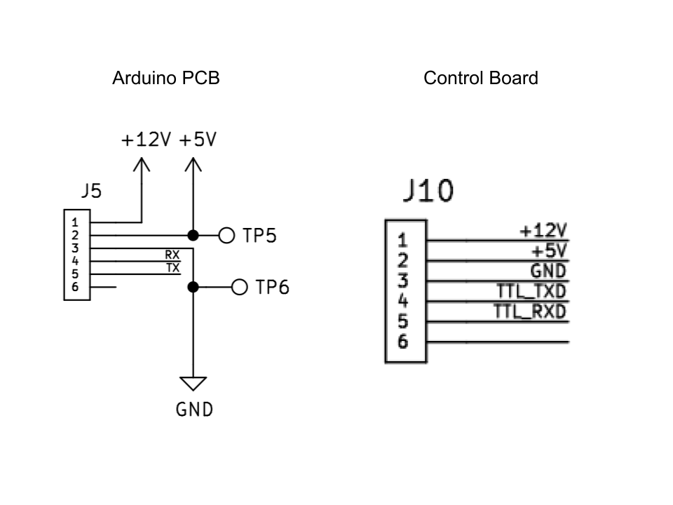
If we were orient the board such that the connector is at the bottom of the board, Pin #1 on the control board is on the Right most pin, and on the control board is on the Left most pin. This means that the connector would have to be facing opposite directions, as long as the cable is made as a passthrough and doesn't mirror the pins. Can you just look at that cable and verify if that cable connects pin 1 of one side to pin 1 of the other side?
If it is not mirrored then I don't think the connectors are wrong in the directions, if the cable is mirrored then the connectors are wrong in the directions.
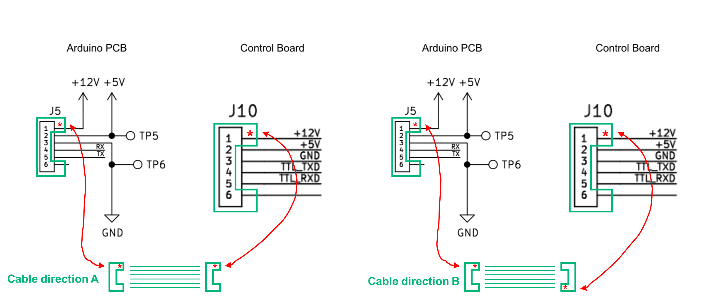
I painted how the cable direction affects the direction of the connector, as shown in the following figure. The cable we bought (E26) is as Cable direction B.
We just need to spin the connector itself. I don't think you need to adjust the electrical part of the PCB design. But perhaps you can mark the correct direction on the PCB.
I'd like to correct that the PCB layout doesn't need to be adjusted, and the schematic and mark may need to be adjusted.