arduino-web-oscilloscope
 arduino-web-oscilloscope copied to clipboard
Can't get a waveform or trigger
Looks amazing but I can't get it to trigger or show a wave form. I have uploaded OK and pressed run. Serial status =Connected. Trigger = Searching. I have a TTL square wave as input. Channel = A0, trigger A0, Auto. Run button is green
I have tried a Chromebook and a Windows 10 PC. The LGT8F328P is connected via a CH340 USB bridge.
Channel A0 is blue and you connected it to channel A0, right? Did you also connect the grounds of the board and your device under test? What time scale and volts per division do you have?
Channel A0 is blue and you connected it to channel A0, right? Did you also connect the grounds of the board and your device under test? Yes. What time scale and volts per division do you have? I tried various timescales down to 61us/div and input frequencies including a few 100Hz. 500mV/div for a 0-5V input signal. I don't know what channel AS is. I tried clicking that as well. I've just tried connecting A0 to TxD. Also A4. No go. Could there be an issue with using a separate FTDI instead of an all-in-one MPU module? [Edited - I have an FTDI USB bridge, not CH340. Also put my 'scope on TxD and RxD when Running. No data!]
Could there be an issue with using a separate FTDI instead of an all-in-one MPU module?
it shouldn't. But if the RTS and DTS lines are not connected, you have to manually reset the board right after it connects. The browser and the MCU exchange some state synchronisation messages at start
My MPU module has no CTS. I noticed I had to reset the board just as I hit Upload. I have now pulled CTS down on the FTDI. No help. I have tried resetting as I Connect, just before and just after I Connect. No help.
There is an issue in the arduino core repo for this board which may be relevant for you: https://github.com/dbuezas/lgt8fx/issues/4
TL;DR "I tried another FTDI breakout board and it works with DTR--writing and reading (verifying). Works at 3.3V as well as 5V."
I have the same issue. Sometimes it works and sometimes it doesn't.
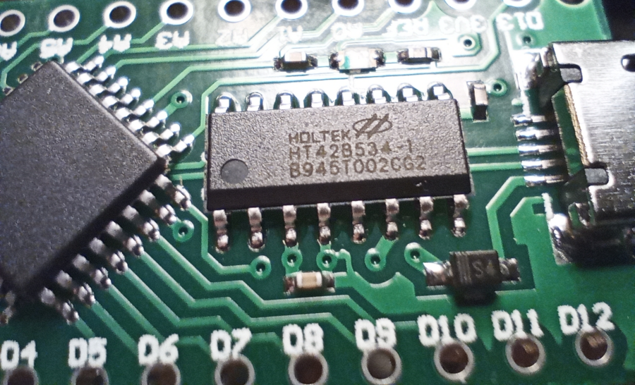
The UART bridge of my board is a HT42B534 but the CTS/RTS pins are left unconnected.
There is an issue in the arduino core repo for this board which may be relevant for you: dbuezas/lgt8fx#4 I can program it with Arduino, setting the board as LGT8F328P-LQPF-32 MiniEVB. It has the SSOP-20 package but I can flash a LED. I must reset it just before I upload.
I've ordered an couple of LGT8F328P nanos with USB. I've just got to try your amazing project.
I have the same issue. Sometimes it works and sometimes it doesn't.
That's interesting... I developed in the same board and I had no issues. If anybody else has issues, please let me know.