DSP.jl
 DSP.jl copied to clipboard
analogfilter design seems to be broken
Please see https://discourse.julialang.org/t/dsp-jl-analog-filter-design/33646/5?u=kumarbalachandran for details.
Here is an attempt to reproduce the above post
# Test script to design an analog highpass elliptic filter with 8 poles and a cutoff
# frequency of 4000 Hz. Various pressing questions arise:
#           1. What is the scaling of parameters for cutoff frequencies?
#           2. Why does an analog filter need a sampling frequency at all?
#           3. Why does the freqs function need a sampling frequency at all? I can
#              understand this for freqz, but 's'?

using DSP
using Plots

fs=4*5000e6 #Hz
# 4 GHz cutoff and a 20 GHz sampling freqency! Why 'fs" at all?
# Should there be a HighpassAnalog function?
responsetype = Highpass(4000e6; fs=fs)
# This at least is okay
designmethod = Elliptic(8, 1.0, 40.0)
# We want ANALOG, not digital
fil=analogfilter(responsetype, designmethod)

# Lets try to plot the response
rng=range(100e6, stop=4200e6, length=500)
resp=freqs(fil, rng, fs)
# The x-axis is in GHz
plot(collect(rng)/1e9, 20*log10.((abs.(resp))))
This gives the following plot
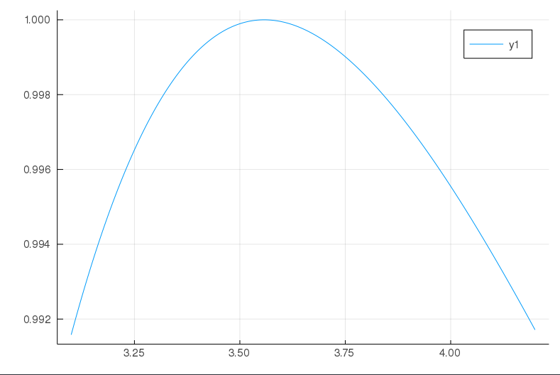
while if I scale the x-axis as
# The x-axis is in GHz scaled by π
plot(collect(rng)/1e9 * π, 20*log10.((abs.(resp))))
I get (voila!)
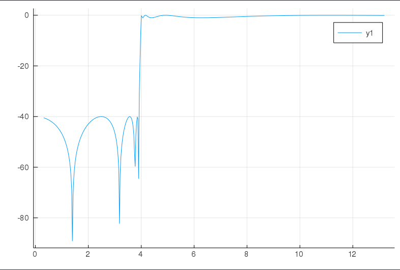
which does not make sense at all. I am not even sure the factor of π is significant as there should be no need to use a sampled data representation in freqs.
I think the interface to analogfilter needs fixing. Please see the comments at the top of the code.
This certainly seems like a bug, and I think you might be right that current interface to design analog filters is problematic.
One option is to create new ftypes AnalogHighPass, AnalogLowPass etc., that take only the cutoff frequency and no sampling frequency.
Alternatively, you can overload LowPass(Float64,String) as Lowpass(fc, "analog"). Numerical stability is a concern.
I really like the data structure design in general, but decoupling the response type from the filter specification makes the analog vs digital design a bit messy. I checked the pole,zero calculations for the Butterworth and Chebychev filters and they are obviously correct for the normalized filters. My guess is that he bug is a consequence of the normalization of the cutoff. @galenlynch Does this seem right to you?
Of course, freqs has to be rewritten to remove the dependence on fs as well.
I'll preface by saying I haven't ever used any of the analog filter design stuff so I may be missing something.
Given that Lowpass, Highpass, etc. don't actually do very much, we could just document that the fs keyword argument is only for digital filters. With the default value fs=2, normalize_freq ends up just being a passthrough so whatever the caller provided is stored in the filter struct, where it can be used in the filter design functions.
That does not work because the cutoff frequency must be below the Nyquist frequency. If I want a cutoff of 4 GHz, I cannot use
HighPass(4000e6; fs = 2)
I think the units matter whether we do Hz or rad/s.
ah, good point. We could move the nyquist check into digitalfilter rather than within the Highpass constructor, given that it doesn't make sense for analog filters.
I agree we need to decide whether the unit should be Hz or rad/s, but I think we can just document whatever the interpretation is (and I'd lean towards Hz).
OK. Here is more troubleshooting for the analog filter. In the code below, I first compared the analog and digital Butterworth to see the scaling that gives identical responses.
# Test script to design an analog highpass elliptic filter with 8 poles and a cutoff
# frequency of 4000 Hz. Various pressing questions arise:
# 1. What is the scaling of parameters for cutoff frequencies?
# 2. Why does an analog filter need a sampling frequency at all?
# 3. Why does the freqs function need a sampling frequency at all? I can
# understand this for freqz, but 's'
using DSP
using Plots
using LaTeXStrings
using MAT
gr()
fs=10*5000e6 # default Hz
# 4 GHz cutoff and a 20 GHz sampling freqency! Why 'fs" at all?
# Should there be a HighpassAnalog function?
# The following is an attempt to get the analog and digital Butterworth Filter
# to have the same response The question remains whether the scaling on the
# analog frequency axis is correct but note the factor of π in the code below
analogresponsetype = Lowpass(4000e6*π; fs=fs)
digitalresponsetype = Lowpass(4000e6; fs=fs)
# This at least is okay
designmethod = Butterworth(8)
# We want ANALOG, not digital, but the digital is for comparison
analogbutterfil=analogfilter(analogresponsetype, designmethod)
digitalbutterfil=digitalfilter(digitalresponsetype, designmethod)
# Lets try to plot the response
rng=range(3000e6, stop=5000e6, length=500)
rng2=range(3000e6, stop=5000e6, length=500)
resp=freqs(analogbutterfil, rng, fs)
resp2=freqz(digitalbutterfil, rng2, fs)
# The x-axis is in GHz scaled by π
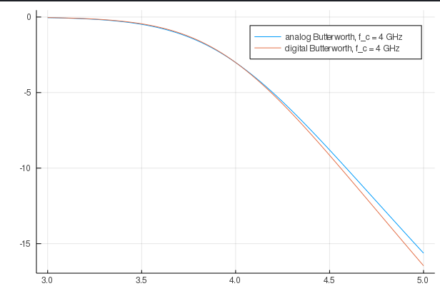
plot(collect(rng)/1e9, 20*log10.((abs.(resp))), label="analog Butterworth, "*"f_c"*" = 4 GHz")
plot!(collect(rng2)/1e9, 20*log10.(abs.(resp2)), label="digital Butterworth, "*"f_c"*" = 4 GHz")
polyfil=convert(PolynomialRatio, analogbutterfil)
file = matopen("analogbutter.mat", "w")
write(file, "b", coefb(polyfil))
write(file, "a", coefa(polyfil))
write(file, "z", analogbutterfil.z)
write(file, "p", analogbutterfil.p)
write(file, "k", analogbutterfil.k)
close(file)
When I plot this in Julia, things match.
However, when I load the coefficients into Matlab, and plot using
load analogbutter
>> w=logspace(-2.1,-1.08)*2*pi;
>> h=freqs(b,a,w);
>> semilogx(w/(2*pi),20*log10(abs(h))),grid
>>
I get the following plot:
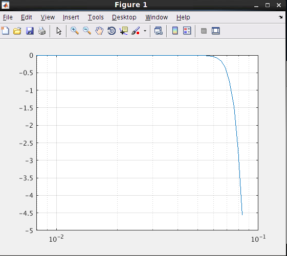
You can see that the cutoff frequency is 0.08 which is really the 4 GHz referred back to a normalization of fs=50 GHz (I guess). So the analog filter is indeed broken as it always keeps the coefficients normalized. I don't quite understand the normalization factor of fs, but this is one step further.
I have a rough workflow for an analog low pass Butterworth filter that could be used to refactor the analogfilter and the freqs functions.
using DSP
using Plots
using LaTeXStrings
using Polynomials
using Measures
# Use the Butterworth prototype
ordr=8
bb=Butterworth(ordr)
BA = convert(PolynomialRatio, bb)
l = @layout [p1; p2]
w=range(0.1, stop=0.16, length=1000)*2*pi
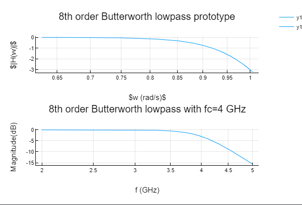
p1=plot(w,20*log10.(abs.(BA.b(1im * w) ./ (BA.a(1im * w)))), title="8th order Butterworth lowpass prototype",
xaxis=:log, xlabel=L"w (rad/s)", ylabel=L"|H(w)|", margin=10mm)
#Prototype has a 3 dB cutoff of 1 rad/s
# translate to 4 GHz cutoff
fc = 4.0e9 #GHz
wc = 2* π * fc #rad/s
W = Poly(wc.^(length(BA.a)-1:-1:0))
b = BA.b * wc^(length(BA.a)-1)
a = Poly(BA.a.a .* W.a)
# Here is the Butterworth at the right cutoff
BBA=PolynomialRatio(b,a)
w=range(2e9, stop=5e9, length=1000)*2*pi
p2=plot(w/(2*pi)/1e9,20*log10.(abs.(BBA.b(1im * w) ./ (BBA.a(1im * w)))),
title="8th order Butterworth lowpass with fc=4 GHz", xaxis=:log,
xlabel="f (GHz)", ylabel="Magnitude(dB)", margin=10mm)
plot(p1,p2,layout=l)
Then, the plots of the magnitude response are:
Oh, it would be good if the PolynomialRatio type was evaluable at a complex frequency or dot evaluable at a range of frequencies.
While ZeroPoleGain and PolynomialRatio are nice data structures, I wonder if there has to be a meta approach to LinearTimeInvariant Systems and have a derivative Filter object. At some level, DSP should be tied into TransferFunction and StateSpace representations. A filtering operation is merely a way of determining the time evolution of a system state.
It would be good if DSP.jl and ControlSystems.jl undergoes a reconciliation to get continuous-time and discrete-time filtering functions in order. The 'tf' system representation in ControlSystems.jl understands whether the frequency variable is 's' or 'z'. None of the existing DSP interfaces need to change, but the filt function could act on the ControlSystems data types. This is of course separate from the bug fix request here and this message probably belongs in discourse, so I apologize for the diversion.
Even Matlab's linear systems packages and the signal processing toolbox do not have this level of integration. This could be a nice functionality for Julia to have.
How about a redesign of the LowPass, HighPasss etc. structures -- e.g.
# fs =some(nothing) makes it continuous time and the Nyquist check is ignored.
struct Highpass{T} <: FilterType
    w::T
    fs::Union{T, Nothing} # default of 2 is no longer allowed.
end
"""
    Highpass(Wn[; fs])
High pass filter with cutoff frequency `Wn`. If `fs` is not
specified, `Wn` is interpreted as a normalized frequency in
half-cycles/sample.
"""
Highpass(wn::Real; fs::Union{T, Nothing} = nothing)
if (fs==some(nothing))
   w=wn;
   fs=nothing;
else
   w=(normalize_freq(w, fs))
   fs=2;
end

function normalize_freq(w::Real, fs::Real)
# Are fs and w always in rad/s?
    w <= 0 && error("frequencies must be positive")
    if fs != some(nothing)
        # Digital filter, normalize
        f = 2*w/fs
        f >= 1 && error("frequencies must be less than the Nyquist frequency $(fs/2)")
    else
        f=w;
    end
    f
end
Does this work? I think the transform_prototype function may still be okay, but I have not tested it yet.
The freqs function has to be rewritten according to the Butterworth example above. Unfortunately, there is no way to verify that the freqz function is not used on an analog filter or the freqs with a digital filter. This is a problem with the way the filter type is designed.
It would be good if DSP.jl and ControlSystems.jl undergoes a reconciliation
I think it would be nice, though inter-package coordination can be quite dicey and lead to headaches with package versioning.
this message probably belongs in discourse
I personally think that discussions about changing packages should occur on the repositories of those packages. I almost never use discourse, though I don't think this is true of the other maintainers.
The 'tf' system representation in ControlSystems.jl understands whether the frequency variable is 's' or 'z'
@martinholters has an open PR #284 that would address some of these concerns. Unfortunately no one has yet been able to give his PR the review that it deserves. I keep meaning to do this soon, though I realistically don't have much free time to devote to this package in the next week or two.
Just checking in, has anything happened here? For people who needs to design an analog filter, overriding this is a workaround that allows you to design analog filters with frequencies higher than 1. Note, after defining the method below, the design of digital filters will be broken instead
function DSP.Filters.normalize_freq(w::Real, fs::Real)
    w <= 0 && error("frequencies must be positive")
    w
end # DSP bug for analog filters https://github.com/JuliaDSP/DSP.jl/issues/341
Hi, I had the same problem, that I wasn't able to design an analog filter approprietely. I'm strongly interested in a bugfix and therefore made up my mind for a meaningful solution.
The main problem from my point of view is as stated before by @kumarbal, that there is no opportunity to construct an "analog" filter response type, i.e. without sampling frequency and frequency normalization. And I would follow the proposal of @Firionus in PR #418 to shift the definition of the sampling frequency and the frequency normalization from the filter response types to the digitalfilter() function. This ends up in a unitless filter response type, i.e. the unit of the cutoff frequencies is just defined by the type of filter design function.
-
If function
digitalfilter()is used, the provided cutoff frequencies are normalized with the functionnormalize_freq()as it is already the case now. That means iffsis provided, the cutoff frequencies are normalized to the provided sampling frequency and if no sampling frequency is provided, the default valuefs=2is used, i.e. the cutoff frequencies are interpreted as normalized frequencies in the range (-1,1). -
If function
analogfilter()is used, no normalization is done. The provided cutoff frequencies are used as is, i.e. they are interpreted in rad/s according to the current implementation.
What do you think?
I could provide a PR. I'm only wondering a little bit, since there was no reaction for a longer time neither on this issue nor on the draft in PR #418.
I don't have much time to contribute right now, but if one of you puts in a PR with the suggested changes, feel free to ping me for comments.