rpi-rgb-led-matrix
 rpi-rgb-led-matrix copied to clipboard
Sigh, new panels: ABC with fm6126A (128x64)
This is starting to get annoying... I get output on them after sending the fm26126A init sequence, but the output is all wrong given the line addressing having changed again. It seems that you only select one of 8 lines, and push 4 times 128 pixels to reach the other 3 rows after filling the first one. Why, oh why do "they" have to keep changing how to do things? I got those as replacements for a perfectly working ABCDE panel
Previous discussions of the quirky fm6126A"
https://github.com/hzeller/rpi-rgb-led-matrix/issues/746
There is some code and comments regarding that chip, in this driver https://github.com/2dom/PxMatrix/blob/master/PxMatrix.h
http://ledpixelart.com/pixelv2board/ declares the FM6126A is not compatible with their setup.
One guy suggests that only init code must be added to solve his FM6126A problem: "I just ported this file so that it works on my rPi, ran it, and then plugged my Teensy with SmartMatrix code (unmodified), and things just worked. So this confirms that the only problem is indeed the init necessary with those FM6126A chips"
https://community.pixelmatix.com/t/smartmatrix-doesnt-support-fm6126a-driver-chips/421
@jake653 "One guy suggests that only init code must be added " => that was me :)
Sorry that my message was unclear, the problem is not FM6126A which is solved with the out of band init code (hopefully will get integrated in the lib proper soon), it's the ABC addressing. @hzeller can you confirm that ABC addressing is not currently supported by your lib (or any other lib I've seen actually)? I've only ever seen AB or ABCD or ABCDE
Sorry that my message was unclear, the problem is not FM6126A which is solved with the out of band init code (hopefully will get integrated in the lib proper soon), it's the ABC addressing.
I have ABC addressing panel using ICN2037, and I was not able to make it work.
If this is an FM61A but only has three address lines, would this probably be working with (the new flag) --led-panel-type=fm6126 and one of the --led-multiplexing options (because outdoor panels do different multiplexing).
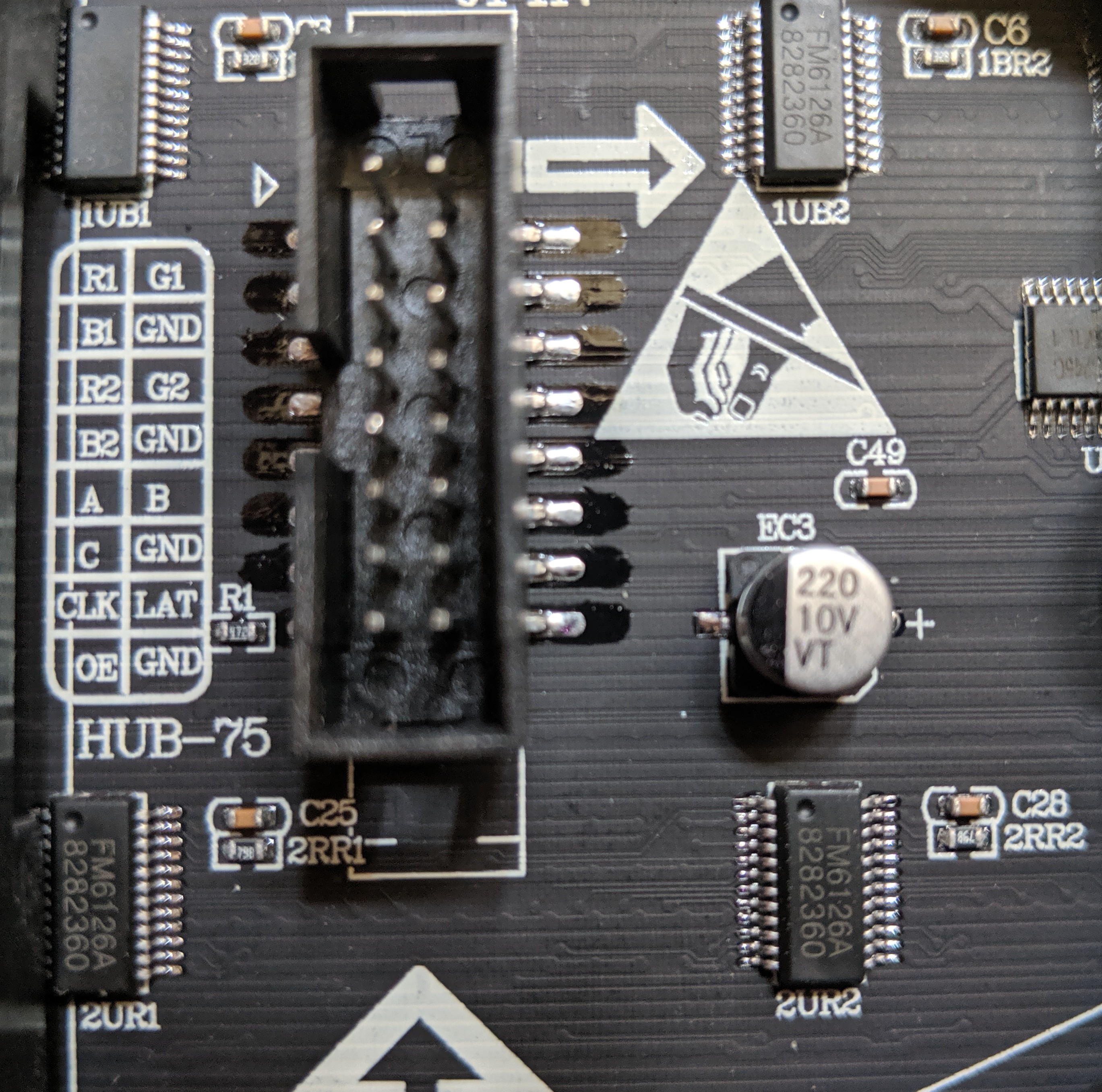
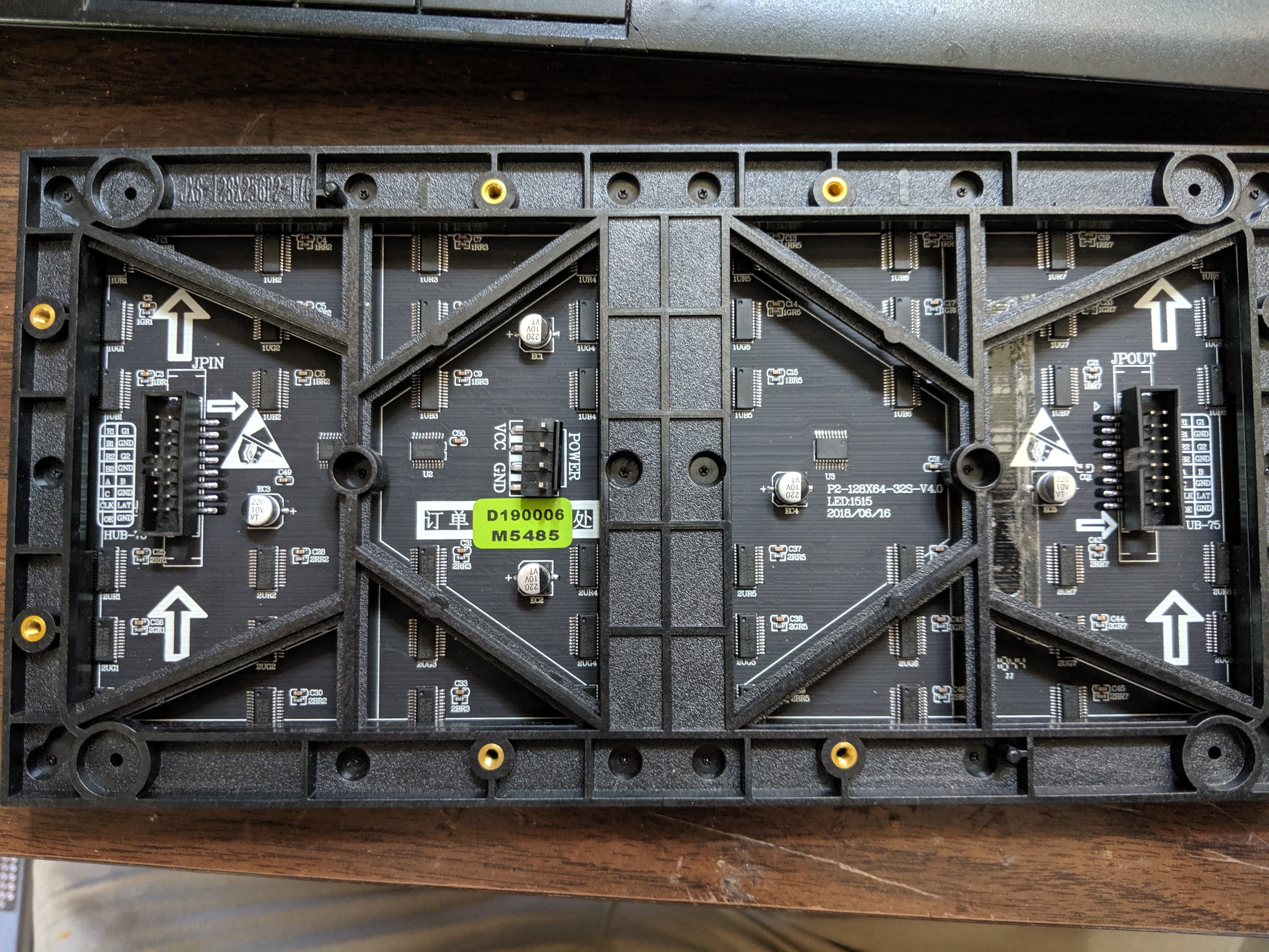
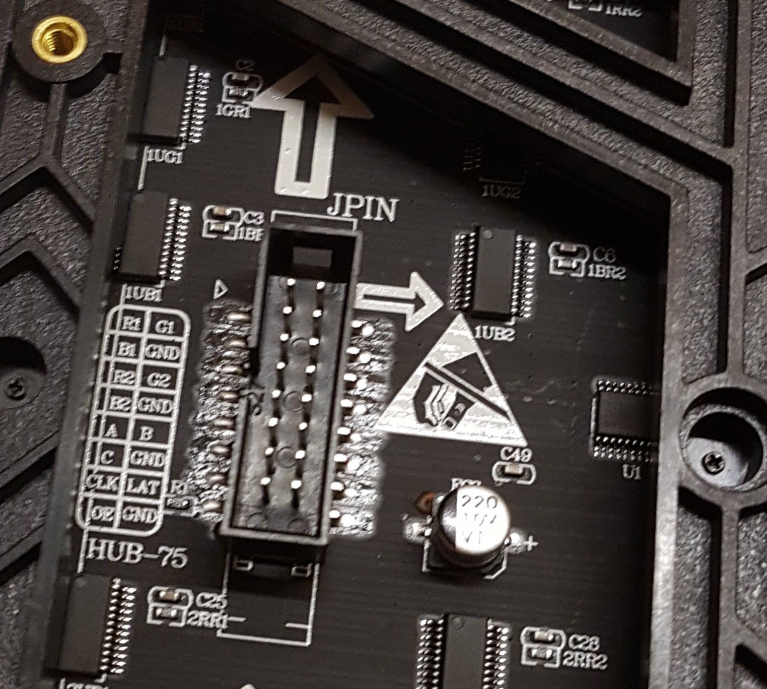
My 64x128 panel is not fm6126, but ICN2037, and it has only ABC lines:
and this is how the demo with -D 3 looks like:

It is written on the panel: P2-128X64-32S-V4.0, LED1515, 2018/06/16
(I have other panels with HUB75E with ICN2037, and those working fine)
ABC sounds like a different led multiplexing. Did you try through the available --led-multuplexing options?
Yes, I tried them, none of them worked.
This is how demo 0 looks like:
sudo ./demo --led-cols=128 --led-rows=64 --led-slowdown-gpio=5 -D 0
It seems for the half of the panel, it repeats 4 line, and the other half, it repeats another 4 line.
ABC could also means some different row address type; there are a few implemented, but they don't do three address lines. It might be worthwhile doing some reverse engineering, then implement this.
It looks a bit like the AB row address type but maybe split into top and bottom half ? So I would try with --led-row-addr-type=1 and see if that at least gives some partial usable output. Then we can go from there.
Hello, I might have the same led panel with the same issue. https://www.aliexpress.com/item/32855350927.html?spm=a2g0s.9042311.0.0.78ba6c37sxIajI I tried all sorts of combination with the parameters but it will give at best the animation shown above (demo0).
sudo ./demo --led-rows=64 --led-cols=128 --led-slowdown-gpio=3 --led-multiplexing=0 --led-scan-mode=0 --led-row-addr-type=0 led-chain=1 led-parallel=1 -D 0
--> this will give the output with two semi cubes rotating exactly like mcpgza's GIF above.
The same demo with --led-row-addr-type=1 will give nothing but a black screen.
I also have one of these ABC-panels and have the same issue as @5onix, @marcmerlin and @mcpgza. I'd love to see this awesome library work with my panel. I would like to help but I don't know where to start 😅 Maybe I can help after hearing computer graphics this semester.
Hi,
I have the same case as @mcpgza. I received two days ago two 128x64 led-matrix with the same ABC addresses and same information written on the panel (P2-128X64-32S-V4.0, LED1515, 2018/06/16). I asked the chinese store from Aliexpress where I bought the panel for some schematics or something useful but they said that their have no information about it
Hi again,
According to the adafruit site (https://learn.adafruit.com/32x16-32x32-rgb-led-matrix/new-wiring), the ABC addresses is the pin arrangement used by 32x16 panels
I don't know if this could be useful to someone. Maybe this panel needs a custom internal mapper...
I also have this 128x64 panel with the ICN2037 and the ABC lines. No luck getting it to work, I get the same image as @mcpgza posted above. Would like to help any way I can.
It seems it requres a new RowAddressSetter, and I would like to wrtire it, but unfortunately I dont understand how it works, dear @hzeller, can you provide a short descrption how it works, what it does. Thanks.
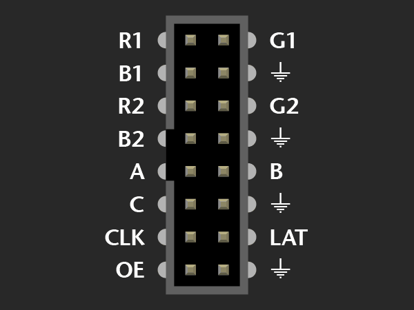
According to Adafruit for the 32x16 Led matrix,
A is the lowest bit of row address B is the second lowest bit of row address C is the highest bit of row address LE is Latch of row CLK is Clock EN is Enable R1 is Red data 1 R2 is Red data 2 G1 is Green data 1 G2 is Green data 2 B1 is Blue data 1 B2 is Blue data 2 GND is Grounding (and 4 GND must be connected)
I think ours panels is the same pinout but with a 1:32 scan multiplexing... Anyway, I've contacted the manufacturer of my led matrix (Coreman.cc). Let's see if I'm lucky and they answer me with the information I've requested
Hi,
I found this forum with some information that can be useful https://community.pixelmatix.com/t/led-module-p2-128-64-1-32-driver/414
I made a huge progress, the panel does not contain inverters, so it use "positive logic", and it seems tha panel has AB type addressing, but B is not used, C used instead.
sudo ./demo --led-cols=128 --led-rows=64 --led-slowdown-gpio=5 --led-row-addr-type=1 -D 0

This is the relevant code:
class ShiftRegisterRowAddressSetter : public RowAddressSetter {
public:
  ShiftRegisterRowAddressSetter(int double_rows, const HardwareMapping &h)
    : double_rows_(double_rows),
      row_mask_(h.a | h.c),
      clock_(h.a),
      data_(h.c),
      last_row_(-1) {
  }
  virtual gpio_bits_t need_bits() const { return row_mask_; }

  virtual void SetRowAddress(GPIO *io, int row) {
    if (row == last_row_) return;
    for (int activate = 0; activate < double_rows_; ++activate) {
      io->SetBits(clock_);
      if (activate == double_rows_ - 1 - row) {
        io->SetBits(data_);
      } else {
        io->ClearBits(data_);
      }
      io->ClearBits(clock_);
    }
    io->SetBits(clock_);
    io->ClearBits(clock_);
    last_row_ = row;
  }

private:
  const int double_rows_;
  const gpio_bits_t row_mask_;
  const gpio_bits_t clock_;
  const gpio_bits_t data_;
  int last_row_;
};
The only problem is a missing line at the end of one part.
Thanks @mcpgza ! I have added your code to the master branch now and it can be selected with --led-row-addr-type=3 so that it is easy to try for everyone.
This then allows others who also have the panel to help figure out the remaining issue with the missing line.
Hi guys,
I'm trying the new option for our 128x64 ABC modules. Apart of the black line, I see two things:
- some LEDs with incorrect colours near the right and left laterals
- If I try to connect 2 128x64 modules in chain, the modules don't show anything and the application freezes
I'll upload some images of these things
Forget the second issue... I incremented the nanoseconds from 300 to 450 and now the chain works fine. Only the of issues with some LEDs:

For your 1st problem, have you tried the demo #4 - Pulsing color or #11 - Brightness pulse generator ? Those demos made me realize that my panel had a few bad subpixels on the edges. The edges are kinda fragile. I had to remove a few leds which weren't working anymore ; due to some accidental bumps they were falling apart.
Hi @5onix I've tried with demos and images (as you can see in my previous message) and the result is the bad subpixels on the edges. My second matrix module is failing and the low quarter of the module has no light (I thing something has broken)
Following a picture of the two modules working together, (the left one is the broken module). I have 3 LEDs broken too (in the right corner of the right module)

Too bad that one of your module has an issue. But overall the result looks very promising.
Here's 2 photos of mine which show broken and malfunctioning pixels.
 The broken pixels are surrounded in blue, the bad ones are in pink.

speaking of P2 panels and pixels that fall off, have you found some kind of glue spray that you can layer on top of them to glue them all in place so that they don't get lost? (and without affecting display quality and/or the space between panels if you put them adjacent to one another)
Good point @marcmerlin, this panels look very fragile and is very easy to lost pixels. (I found 2 of the pixels, but I don't know how to glue them to the panel again) In the other hand, I'm arguing with the seller because I think the panel arrived broken
@gustavoalara you need both. I also had a panel that was not protected correctly in shipping and arrived with some detached pixels, but trust me when I tell you that you will lose more unless you encase this in some way, or never touch/move it, so you might as well practice with the damaged panel :)
Epoxy resin maybe ? I might try with my already pixel missing panel to see if it renders the light & colors correctly with a thin layer of it.
Then, you thing the LEDs with incorrect colours are damaged too? Well, maybe if I'm lucky the seller will send me another panel and I can practice with the damaged panel as @marcmerlin said...