hackrf
 hackrf copied to clipboard
Poor Rx on VHF and below
Steps to reproduce
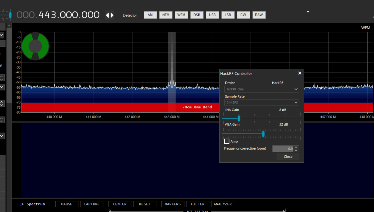
- Tune in to 443.000MHz
- Set LNA Gain = 8dB, VGA Gain = 32dB, AMP = OFF
- Note the results
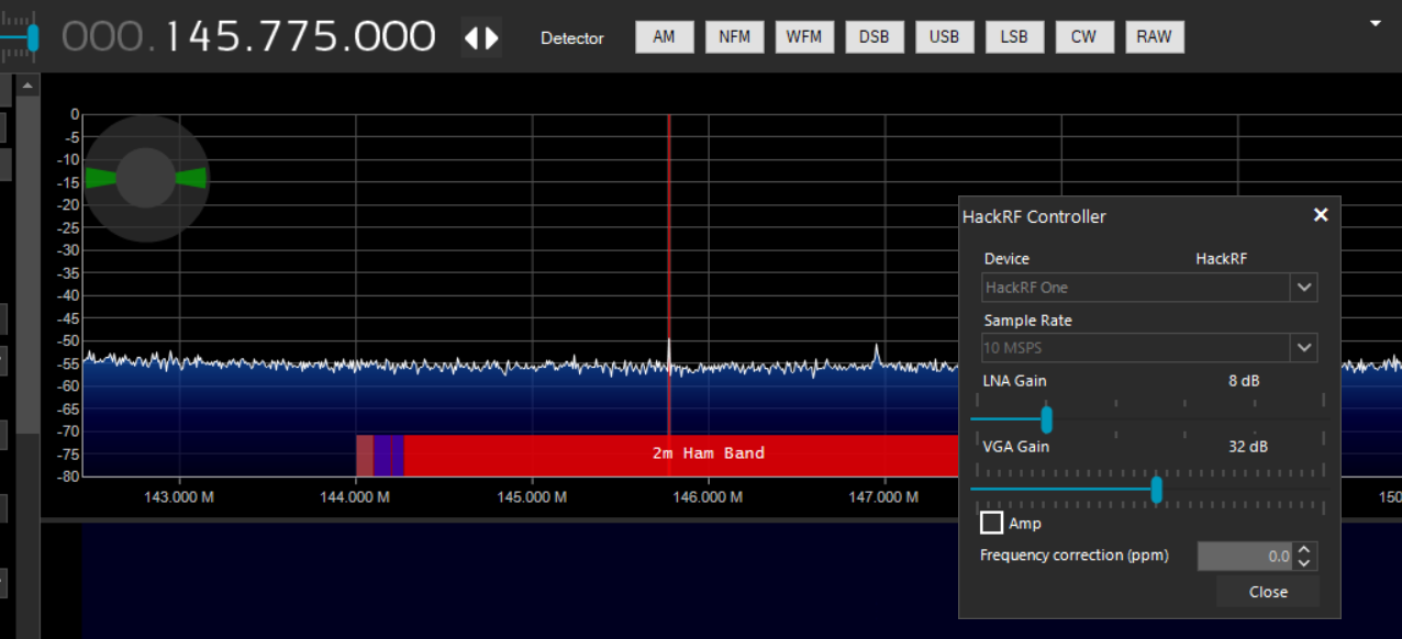
- Tune in to 145.775MHz
- Set LNA Gain = 8dB, VGA Gain = 32dB, AMP = OFF
- Note the results
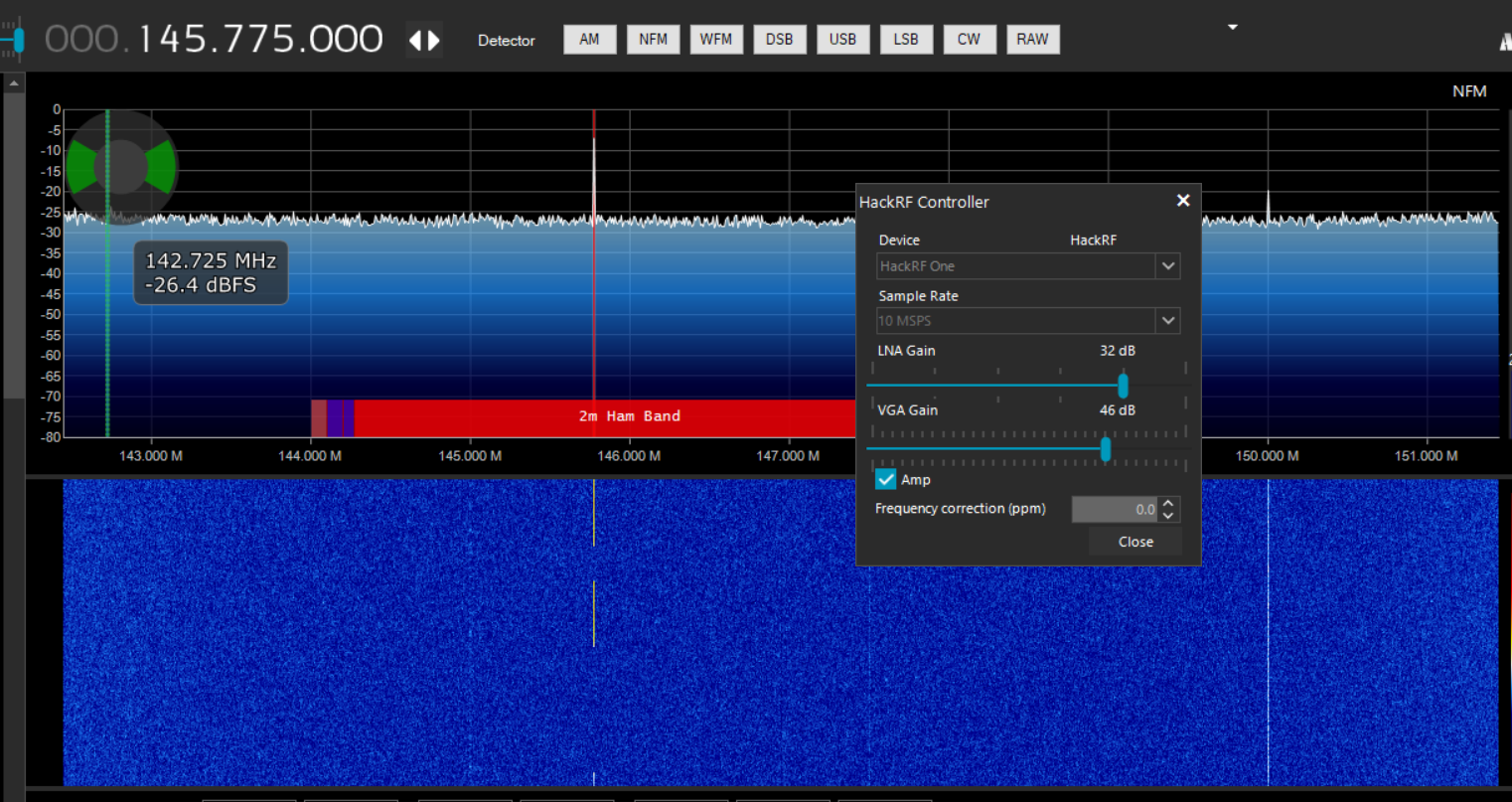
- Set LNA Gain =32dB, VGA Gain = 46dB, AMP = ON
- Note the results
Expected behaviour
I should see sharp, tall spikes on all the above occasions.
Actual behaviour
I see such spikes only on the 70cm UHF frequencies. But on the lower frequencies (FM Broadcast range, 144MHz, 138MHz etc.), there is almost no signal received.
I replaced the U13 MGA81563 LNA to see if that is the culprit. But it seems not. The noise floor goes up when Amp is turned ON.
Version information
Using Windows 10, SDR Sharp 1.0.0.1732
Output
Screenshot of UHF rx. Works great.
Screenshot of VHF rx. Amp OFF.
Screenshot of VHF rx. Amp ON.
Any thoughts on this, please? Thanks in advance, Tharanga-4S6TMP.
Can you tell me more about why you expect tall spikes in all of the instances you've highlighted?
Hi @straithe,
The first one on UHF shows good reception. The next two with AMP on and off shows very poor (almost nil) reception. In both cases the Tx was a few feet away from the hackRF Rx.
Let me summarize again. I am seeing poor reception on frequencies below 300MHz. I am wondering why that happens.
What equipment are you using to generate the test signal? What is the transmit power level? Is it the same power level at both 433 MHz and 145 MHz?
I am Txing using an HT with ~5W (both VHF & UHF). Distance between the HackRF & HT is unchanged,
At that power level the received signal strength should be so high that it clips and produces harmonics all over the spectrum. I'm not seeing that, so I think that a broken solder joint in the RF path is attenuating the signal at all frequencies but with even greater attenuation at lower frequencies.
I recommend contacting the seller of your HackRF for a replacement.
5 W in close proximity is enough to exceed the maximum power limit of HackRF One, by the way. It is likely to cause damage if one of the RF amplifiers is enabled, but it your case there is probably a different problem which may make damage less likely.
My thoughts exactly. BTW I did not Tx for long, just PTT for a second and let go.
My problem is why the reception is so poor on VHF but not UHF? I started replacing the antenna switches and RF Amps. I will keep this thread updated.
Thank you @mossmann
A tiny crack in a solder joint acts like a capacitor (in series) which is why it attenuates lower frequencies more than higher frequencies. There is a good chance that the break is undetectable above some even higher frequency like 2 GHz.
I'm closing this as there hasn't been a response in the last thirty days, but please re-open this issue or open a new one if you still need assistance.