avr-io
 avr-io copied to clipboard
Control an ATmega328P via I2C
avr-io
Firmware for the ATmega328P which allows it to function as an I2C device and have it's pins controlled via I2C. When running the firmware, the ATmega can be accessed at it's default address of 0x28 on an I2C-bus.
When the ATmega328P is clocked at 8MHz, the firmware will function on an I2C-bus running at speeds of up to 100KHz without stretching the I2C clock.
Usage
Blink an LED:
var i2c = require('i2c-bus').openSync(1);

var OUTPUT = 1;

var AVR_ADDR = 0x28,
  P8_MODE = 0x20,
  P8_VALUE = 0x21;

i2c.writeByteSync(AVR_ADDR, P8_MODE, OUTPUT);

setInterval(function () {
  i2c.writeByteSync(AVR_ADDR, P8_VALUE,
    i2c.readByteSync(AVR_ADDR, P8_VALUE) ^ 1);
}, 500);
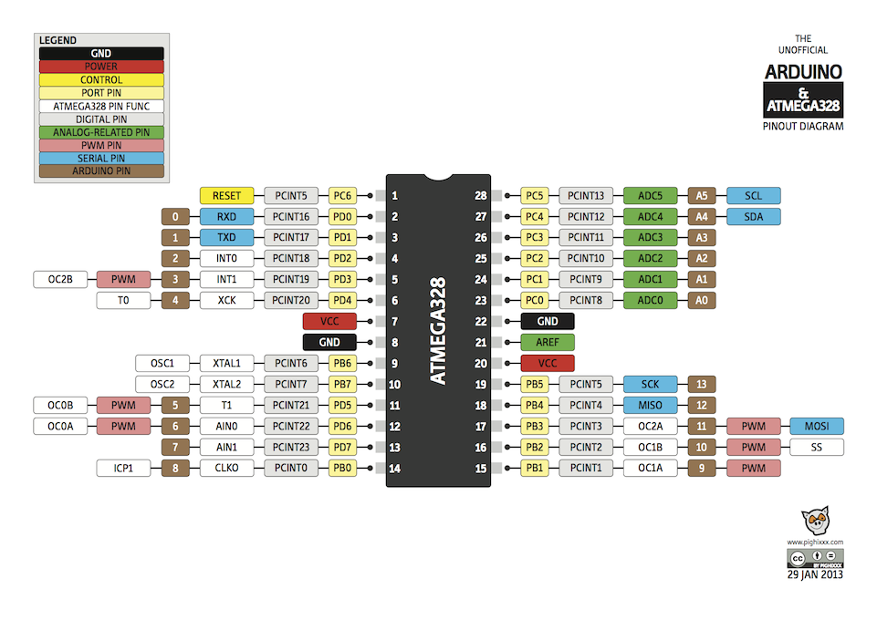
Pin Function Descriptions

Register Map
| Address | Name | Reset Value | Arduino Pin | ATmega328P Pin | Description |
|---|---|---|---|---|---|
| 0x00 | P0_MODE | INPUT | 0 | 2 | Mode pin 0 |
| 0x01 | P0_VALUE | 0 or 1 | 0 | 2 | Value pin 0 |
| 0x04 | P1_MODE | INPUT | 1 | 3 | Mode pin 1 |
| 0x05 | P1_VALUE | 0 or 1 | 1 | 3 | Value pin 1 |
| 0x08 | P2_MODE | INPUT | 2 | 4 | Mode pin 2 |
| 0x09 | P2_VALUE | 0 or 1 | 2 | 4 | Value pin 2 |
| 0x0c | P3_MODE | INPUT | 3 | 5 | Mode pin 3 |
| 0x0d | P3_VALUE | 0 or 1 | 3 | 5 | Value pin 3 |
| 0x10 | P4_MODE | INPUT | 4 | 6 | Mode pin 4 |
| 0x11 | P4_VALUE | 0 or 1 | 4 | 6 | Value pin 4 |
| 0x14 | P5_MODE | INPUT | 5 | 11 | Mode pin 5 |
| 0x15 | P5_VALUE | 0 or 1 | 5 | 11 | Value pin 5 |
| 0x18 | P6_MODE | INPUT | 6 | 12 | Mode pin 6 |
| 0x19 | P6_VALUE | 0 or 1 | 6 | 12 | Value pin 6 |
| 0x1c | P7_MODE | INPUT | 7 | 13 | Mode pin 7 |
| 0x1d | P7_VALUE | 0 or 1 | 7 | 13 | Value pin 7 |
| 0x20 | P8_MODE | INPUT | 8 | 14 | Mode pin 8 |
| 0x21 | P8_VALUE | 0 or 1 | 8 | 14 | Value pin 8 |
| 0x24 | P9_MODE | INPUT | 9 | 15 | Mode pin 9 |
| 0x25 | P9_VALUE | 0 or 1 | 9 | 15 | Value pin 9 |
| 0x28 | P10_MODE | INPUT | 10 | 16 | Mode pin 10 |
| 0x29 | P10_VALUE | 0 or 1 | 10 | 16 | Value pin 10 |
| 0x2c | P11_MODE | INPUT | 11 | 17 | Mode pin 11 |
| 0x2d | P11_VALUE | 0 or 1 | 11 | 17 | Value pin 11 |
| 0x30 | P12_MODE | INPUT | 12 | 18 | Mode pin 12 |
| 0x31 | P12_VALUE | 0 or 1 | 12 | 18 | Value pin 12 |
| 0x34 | P13_MODE | INPUT | 13 | 19 | Mode pin 13 |
| 0x35 | P13_VALUE | 0 or 1 | 13 | 19 | Value pin 13 |
| 0x38 | P14_MODE | INPUT | A0 | 23 | Mode pin A0 |
| 0x39 | P14_VALUE (LSB) | 0 or 1 | A0 | 23 | Value pin A0 (LSB) |
| 0x3a | P14_VALUE (MSB) | 0 | A0 | 23 | Value pin A0 (MSB) |
| 0x3c | P15_MODE | INPUT | A1 | 24 | Mode pin A1 |
| 0x3d | P15_VALUE (LSB) | 0 or 1 | A1 | 24 | Value pin A1 (LSB) |
| 0x3e | P15_VALUE (MSB) | 0 | A1 | 24 | Value pin A1 (MSB) |
| 0x40 | P16_MODE | INPUT | A2 | 25 | Mode pin A2 |
| 0x41 | P16_VALUE (LSB) | 0 or 1 | A2 | 25 | Value pin A2 (LSB) |
| 0x42 | P16_VALUE (MSB) | 0 | A2 | 25 | Value pin A2 (MSB) |
| 0x44 | P17_MODE | INPUT | A3 | 26 | Mode pin A3 |
| 0x45 | P17_VALUE (LSB) | 0 or 1 | A3 | 26 | Value pin A3 (LSB) |
| 0x46 | P17_VALUE (MSB) | 0 | A3 | 26 | Value pin A3 (MSB) |
Modes
| Number | Name |
|---|---|
| 0 | INPUT |
| 1 | OUTPUT |
| 2 | ANALOG |
| 3 | PWM |
| 5 | INPUT_PULLUP |
Supported Modes
| Arduino Pin | Modes |
|---|---|
| 0 | INPUT, OUTPUT, INPUT_PULLUP |
| 1 | INPUT, OUTPUT, INPUT_PULLUP |
| 2 | INPUT, OUTPUT, INPUT_PULLUP |
| 3 | INPUT, OUTPUT, INPUT_PULLUP, PWM |
| 4 | INPUT, OUTPUT, INPUT_PULLUP |
| 5 | INPUT, OUTPUT, INPUT_PULLUP, PWM |
| 6 | INPUT, OUTPUT, INPUT_PULLUP, PWM |
| 7 | INPUT, OUTPUT, INPUT_PULLUP |
| 8 | INPUT, OUTPUT, INPUT_PULLUP |
| 9 | INPUT, OUTPUT, INPUT_PULLUP, PWM |
| 10 | INPUT, OUTPUT, INPUT_PULLUP, PWM |
| 11 | INPUT, OUTPUT, INPUT_PULLUP, PWM |
| 12 | INPUT, OUTPUT, INPUT_PULLUP |
| 13 | INPUT, OUTPUT, INPUT_PULLUP |
| A0 | INPUT, OUTPUT, INPUT_PULLUP, ANALOG |
| A1 | INPUT, OUTPUT, INPUT_PULLUP, ANALOG |
| A2 | INPUT, OUTPUT, INPUT_PULLUP, ANALOG |
| A3 | INPUT, OUTPUT, INPUT_PULLUP, ANALOG |