Overhead wires in Netedit
Dear all, but mostly @palvarezlopez,
I would like to extend Netedit to provide functionality for
- adding overhead wires over selected edges and lanes,
- adding substations,
- adding substation connection points,
- adding overhead wire clamps (i.e. place).
For this I would prefer to refactor parts of already existing code in Netedit (route editing) and Sumo (e.g. our own GUI routines that draw the overhead wires) and I would welcome suggestions how to implement this in a least-intrusive manner. As @palvarezlopez is probably the developer most familiar with Netedit internals, I am explicitly mentioning him.
Overhead wire on a lane
A very short reminder how we defined the overhead wire infrastructure in Sumo:
The overhead wire is in fact a two-level hierarchy: At the top level we have an overhead wire section, which represents a continuous traction wire spanning multiple edges and lanes, powered from a traction substation at least at one connection point (multiple connection points are possible). An overhead wire segment represents the lower hierarchy level; in our implementation it matches a lane of an edge. The section is constructed from multiple segments, and internal lanes of junctions where the segments connect are automatically added when building the network, i.e. the internal segments are not specified in the additional file.
The overhead wire is defined in microsim/triggers as the MSOverheadWire class. It is a descendant of MSStoppingPlace class defined in microsim [1]. The drawing of overhead wires in the simulation GUI is carried out by the GUIOverheadWire class that is defined in guisim.
Proposal
By looking at the Netedit functions, I can see that Netedit offers a mechanism to create routes by manually marking the edges where a vehicle shall travel. This suggests a way how to construct the overhead wire network:
- users create a new overhead wire section container which is empty, and give it some name;
- users then add overhead wire segments to this section container using a mechanism similar to creating routes in Netedit, i.e., marking lanes where the wires are installed;
- at the end we have to check that the overhead wire section is continuous and no gaps exist in the sequence of segments;
- as mentioned above, the traction wires over internal lanes will be constructed when reading the overhead wire network into Sumo.
Concerning the GUI, the graphical interface for editing additional element creates a dialogue as a left hand column of the main Netedit window. We could be probably split that into two parts, the upper one containing a list of already defined sections plus buttons to add/delete/edit them, and the lower one containing the parameters of the section. The question is where to edit the segment parameters (e.g. how to say "this is the place where a traction substation is connected").
As the section is connected to a traction substation, we should probably require that the traction substation (which at the moment has no GUI representation) is created first. But maybe this can be left out to the point where we define the connection point of a traction substation.
Netedit internals
Looking at the Netedit source, my guess is that the class responsible for path operations would be the GNEFrameModuls::PathCreator, and the class responsible for route editing is GNERouteFrame, am I correct? Can I use them as a starting point or is there a better way?
Thanks!
Jan
[1] This is probably wrong, as the overhead wire is not a stopping place; on the other hand, we need the functionality provided by the
MSStoppingPlaceclass to conveniently manage theMSOverheadWiregeometry -- i.e. the starting and ending point on the lane andgetBeginLanePosition()/getEndLanePosition(), together with the query functionality for the presence of overhead wires on neighbouring edges and lanes, which is currently implemented usingMSNet::getInstance()->getStoppingPlaceID()andMSNet::getInstance()->getStoppingPlace()(are there any other reasons?).
Off topic: Maybe we should use this opportunity and split the
MSStoppingPlaceinto a parent classMSLinearElementthat specifies generic parameters needed by bothMSStoppingPlaceandMSOverheadWire?
Since your ticket is more elaborate, I'm closing the duplicate (#9368)
Here are some remarks
- Netedit already handles elements that don't have an obvious network location but are used to group other objects (e3Detector, rerouter, ...). We can use this mechanism to accomodate tractionSubstation and overheadWire and overheadWireClamp along with overheadWireSegment.
- Creating many segments with a few reference lanes (similar to a route with edges) makes perfect sense
- Creating a new frame for this quite necessary. How to organize the different parts can be fleshed out later
- creation of the different object types could be done with a drop-down menu as in additional mode
- setting individual object attributes can also be handled via inspect mode )most of the overheadWireSegment attributes seem to be implicit in drawing a "route")
- In addition manual editing, OSM import could be a huge timesaver: #9481
@palvarezlopez I have been playing with this as well and just realised that you started with some modifications ;-). My development cycle is definitely slower (I can spend like 2 hours / week on this, and only if everything else works here), but my changes were mostly concentrated on re-using the route creation code and modifying the PathCreator subclass in GNEFrameModuls to allow lane selection (as we need to select lanes, not edges), plus, as I can see, some GUI tweaks that look very similar to yours. But it is nothing fancy, with your knowledge of Netedit code you can probably replicate this in a jiffy.
If there is something I could help with, and which will not block you due to my long turnaroud time, let me know.
@jprk yes, I started this week with the new Wire mode. I need to adjust the PathCreator for other task too, then the new features will be used in Wire mode. Probably I will need your help for testing the wire mode. When I have a first version, I write you :)
@jprk Data modelling question:
Could it be that that <overheadWireSegment> attributes startPos and endPos are only needed for the first and last segment (because the wire is otherwise continuous)?
If that were the case, we could consider eliminating the overheadwireSegment element from the xml input.
Instead the user would specifiy <overheadWire lanes="...." startPos="X" endPos="Y" volateSources="lane1 lane5"/> .
The overheadWireSegments would still be created within sumo but xml and netedit UI would be simpler.
Or do we need startPos, endPos also in between a wire?
@jprk Data modelling question: Could it be that that
<overheadWireSegment>attributes startPos and endPos are only needed for the first and last segment (because the wire is otherwise continuous)?
Yes, we need them only for the first and last segment of the wire to mark positions where the wire starts or ends (typically at a bus stop, where the trolley poles are being connect to the overhead wire -- this operation sometimes needs more than one attempt as it is quite easy to miss the wire).
If that were the case, we could consider eliminating the overheadwireSegment element from the xml input. Instead the user would specifiy
<overheadWire lanes="...." startPos="X" endPos="Y" volateSources="lane1 lane5"/>. The overheadWireSegments would still be created within sumo but xml and netedit UI would be simpler.
Good idea. Note that we might need additional parameters (like forbiddenInnerLanes) and we need to specify the binding between the substation and the wire, which is currently also part of the <overheadWire> tag. I am Cc:ing this to @kubasevca as well in case he has additional comments to this.
Or do we need startPos, endPos also in between a wire?
No, definitely not.
Cheers,
Jan
Then I suggest we deprecated overheadWireSegment (we can still let sumo handle it for backward compatibility) but only support the new element workflow in netedit (overheadWire is then even more similar to a vehicle route).
@jprk I have more questions:
-
Could exist an overheadWire without TractionSubstation? This overheadWire could either doesn't have current (i.e. voltage = false) or have electricity thought a Clamp to another overheadWire with TractionSubstation
-
An overheadWireClamp could be enabled or disabled? (with attribute "off = true/false). Related with question 1), if this clamp is disabled, and a certain overheadWire's electricty is provided thought this clamp, then their voltage value changes to false, right?
-
An overheadWire's electricity can be provided by two sources? (for example, a TractionSubstation and an overheadWireClamp)
-
An overheadWire or an overheadWireClamp can transmit a certain maximum current?
@jprk and another question: Do you require sumo backward compatibility for loading the old <overheadWireSegment> or would a script to convert the old data into the new format be enough?
@namdre Sorry, got a flood of messages from Github that I am over quota and I deleted also the notification regarding this thread.
Concerning the backward compatibility: I confirm that we do not need backward compatibility for loading the old <overheadWireSegment> data. We are at the moment probably the only users of this part and we can easily update our configuration files.
@palvarezlopez sorry if it is too long and incomprehensible, if I am just confusing things up, let me know and I will try to reiterate ...
@jprk I have more questions:
- Could exist an overheadWire without TractionSubstation? This overheadWire could either doesn't have current (i.e. voltage = false) or have electricity thought a Clamp to another overheadWire with TractionSubstation
In theory, we could have an unconnected traction wire, yes. But an unconnected traction wire should probably generate an error when it is read in by the simulator, as simulation of electrical circuit without voltage source does not make any sense.
Concerning the clamps: In theory, clamps could transmit power to an isolated part of an overhead wire circuit. However, in all practical situations, the "clamp" thing is only used to improve the electric resistance parameters of the circuit, not to ensure that an otherwise isolated part of the circuit gets power.
The voltageSource="true" attribute only indicates that the beginning point of this <overheadWireSegment> is connected to a substation. Internally it means that a voltage source will be added here. The new approach suggested by @namdre would then replace the set of <overheadWireSegment id="..." lane="xyz" voltageSource="true"> elements with <overheadWire lanes="...." startPos="X" endPos="Y" volateSources="lane1 lane5"/> (see above).
- An overheadWireClamp could be enabled or disabled? (with attribute "off = true/false). Related with question 1), if this clamp is disabled, and a certain overheadWire's electricty is provided thought this clamp, then their voltage value changes to false, right?
A clamp is a fixed piece of (thick) wire, connected at both ends to the appropriate overhead trolley wire. In your terminology it is always "on", it either exists or its doesn't. I can think of experimental situations where we would place a set of clamps at different parts of the circuit and then enable/disable them, but this scenario is easily achievable also with a relatively simple script.
- An overheadWire's electricity can be provided by two sources? (for example, a TractionSubstation and an overheadWireClamp)
The only electricity sources in the overhead wire circuit are the traction substations. A single TractionSubstation may power more than one "branch" (i.e. <overheadWire> circuit) and a single <overheadWire> may have more than one connection point to the circuit from the same substation (this improves the electric parameters of the circuit). The only voltage sources in the circuit are those that represents substation connection points.
From the electrical point of view, the "clamp" is only a short piece of wire that connects two points in the overhead electric circuit to improve its internal resistance. The "clamp" is just a wire, it does not have the properties of an voltage source.
- An overheadWire or an overheadWireClamp can transmit a certain maximum current?
The maximum current is a property of the TractionSubstation only. As the requested power in the circuit rises (e.g. you start with 2 vehicles connected to the same substation, and later you have 10 of them wanting to accelerate at the same time), the requested current rises as well, meaning that the traction substation needs to deliver more energy. This cannot go up forever, and therefore the substation it has a current limiter device (OCP, over current protection) that disconnects the circuit from the substation when its power requirements are too high.
As a side note the electric parameters of any wire also determine the maximum current that can be transmitted, but we currently ignore that (e.g. too high current may turn your overhead wire network in a kind of electric heater, with a lot of funny and at the same time dangerous side effects due to thermal dilatation).
@jprk I have a question: we have two differentes attributes for the same concept, das Substation ID. In the input file we use "substationId", but in the output "tractionSubstationID". Is there any reason for this? Can we merge both attributes into substationId?
Dear @palvarezlopez I finally have a free slot to hopefully finish this. I have tested the current functionality in netedit and it works almost perfectly. At the moment I have only the following three remarks:
- netedit allows more than one
<overheadWire>element on a lane, this is in theory fine (but unlikely). It does not detect overlaps though, so I can create wires that are on top of each other and that definitely should not be possible. - when creating an
<overheadWire>element, I am allowed to place a wire endpoint at whatever lane I have already chosen to be part of the wire (see the attached screenshot) - it would be nice if the exported
<overheadWire>could containvoltageSource="lane lane ..."attribute that would specify where the substation is connected to the given overhead wire section; I would be happy to add it by myself, but need someone to point me at the appropriate part of the code ...
I can probably also address 1 and 2, just let me know that I am free to go so that we do not duplicate our efforts.
Ref. 2 - before: 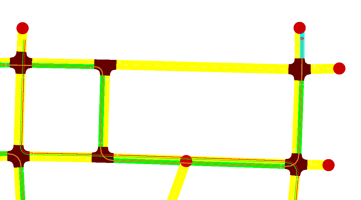 Ref. 2 - after:
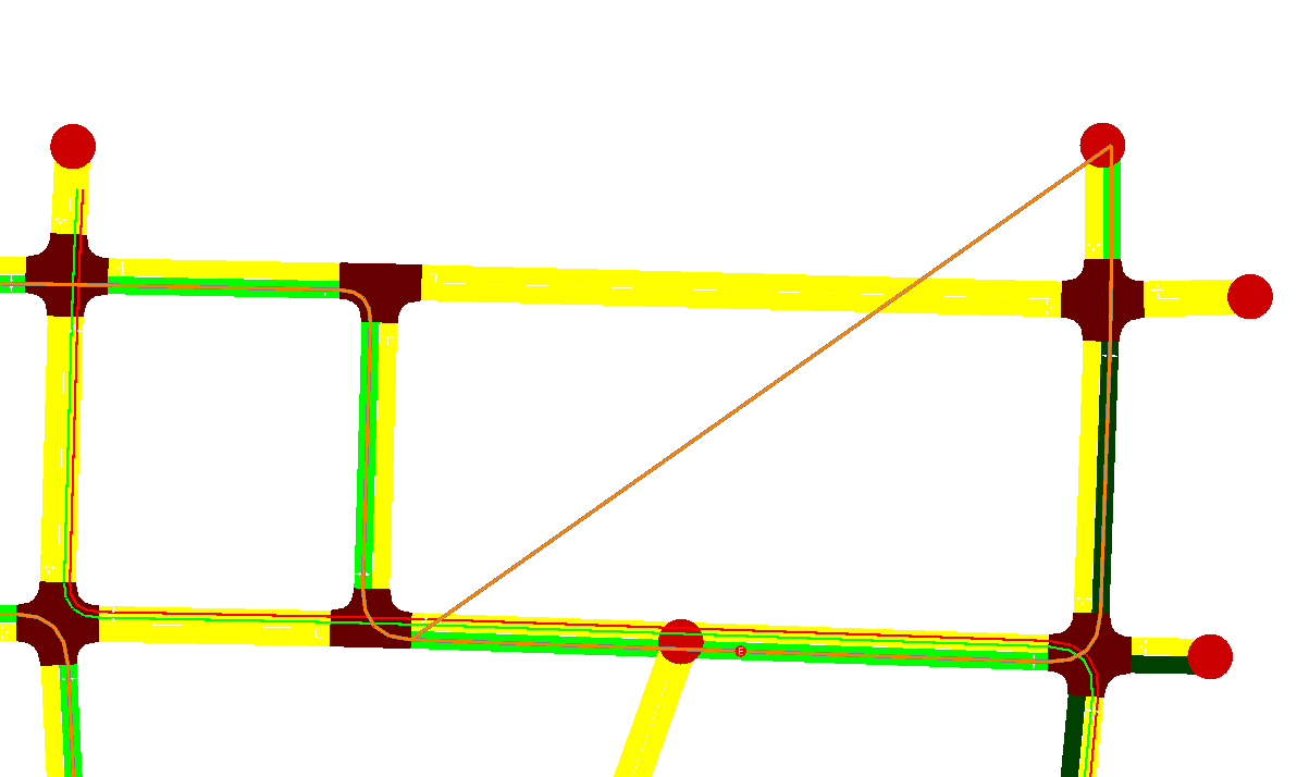
Jan
@jprk I have a question: we have two differentes attributes for the same concept, das Substation ID. In the input file we use "substationId", but in the output "tractionSubstationID". Is there any reason for this? Can we merge both attributes into substationId?
Sorry, not sure if I replied to this e.g. by e-mail: Yes, it is safe to use substationId everywhere, it is the same.
@jprk Thanks for the Feedback :) I'm going to continue working in overhead wires after the next release.
@palvarezlopez Another small glitch that I found when editing wires:
If you happen to click on an intersection instead of a lane (happened to me for example with roundabouts in Pilsen), netedit currently crashes.
That being said, if there is anything I can do that would help you, let me know. I admit that my time is limited, but even at this stage the wire editing mode is a big help for myself and my students.
@jprk Thanks for the Feedback! I'm going to try to remove it as soon as possible.
About the help, I would be very grateful if you can adapt the SUMO code for the following input:
    <!-- Wires -->
    <tractionSubstation id="tr_0" pos="-40.00,100.00" voltage="600.00" currentLimit="400.00"/>
    <overheadWire id="ow_0" substationId="tr_0" lanes="gneE10_1 gneE11_0" startPos="10.00" endPos="15.00"/>
    <overheadWire id="ow_1" substationId="tr_0" lanes="gneE11_0 gneE12_0" startPos="25.00" endPos="5.00"/>
That is a portion of code that I already have mostly finished. There is one related change in netedit though: Every <overheadWire> entity needs to have "connection points" specified, i.e. lanes where the traction substation is connected to the wire. At least one connection point has to exist. In the current development code we have it specified using an additional voltageSources attribute. Your definition of ow_0 would then become something like
<overheadWire id="ow_0" substationId="tr_0" lanes="gneE10_1 gneE11_0" voltageSources="gneE10_1 gneE11_0" startPos="10.00" endPos="15.00"/>
with both lanes having separate connection to the substation. Currently I am adding the connection points manually, it is not a big hassle.
I will prepare a PR with the full change for review, but probably not before the next Friday, I have an awful lot of things on my plate now :-(
@jprk Just to be clear:
You would like to support the new mandatory attribute voltageSources on element overheadWire which should be a non-empty list of strings. Correct?
What are the permitted values of `voltageSources?