Question concerning the calibration and the patterns
Hello,
When performing the camera calibration in DICe, is the software using parameters for the dots' diameter or the inner diameter ratio for the special corner dots?
I am asking this question since we tried performing calibration using "homemade" grids. The pattern of the homemade calibration grids were generated using the tool provided by a commercial DIC system provider. However, the calibration of DICe does not recognize our special corner dots.
The following images compare the calibration obtained with a calibration grid provided by a DIC system provider and our homemade grids:

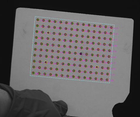
As can be seen, the special corner dots are recognized for the commercial grid, but not for ours. The images were acquired using the exact same setup. The grids use the same spacing and number of dots. The main difference remains within the dots' diameter and the inner diameter ratio of the special corner dots. We tried varying those parameters, without success.
Thank you for your help
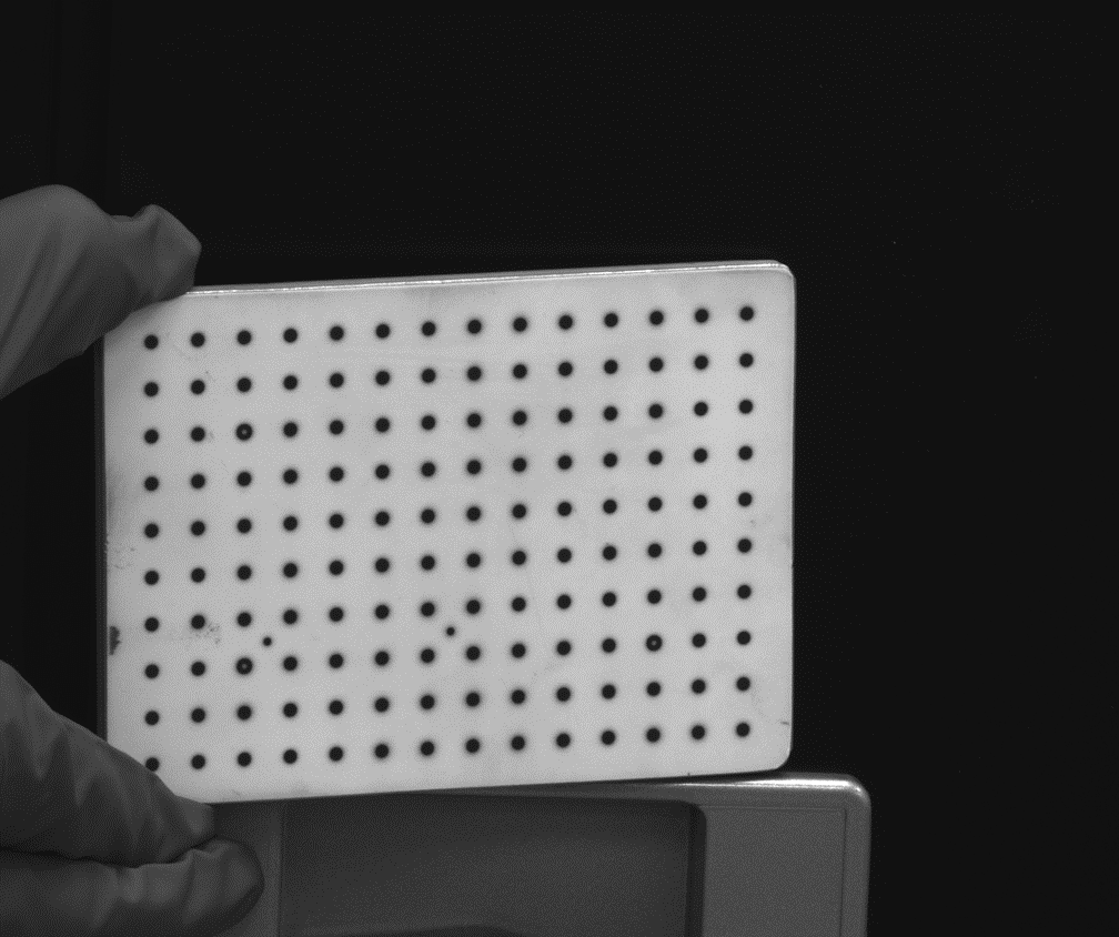
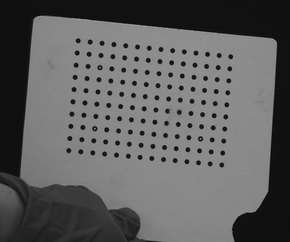
Here's pictures of the calibration grid without the added calibration marks:
Hi ollamc,
There are couple issues that could be causing it to fail. The first is that there is a minimum size for the white dot in the middle of the special marker dots. It's not the ratio of the inner to the outer dots, it's the size of the inner dot. This was done to prevent image noise from being mistaken as the marker dot. The inner white dots should be 4 or 5 pixels across.
The second issue is that since your marker dots are so small they are getting aliased so the contrast between the inner white dot and the black ring is pretty bad.
Hopefully that gives you some good leads on how to improve your homemade pattern.