Weird Displacement for yy direction for Tensile test
Hi, Dice community:
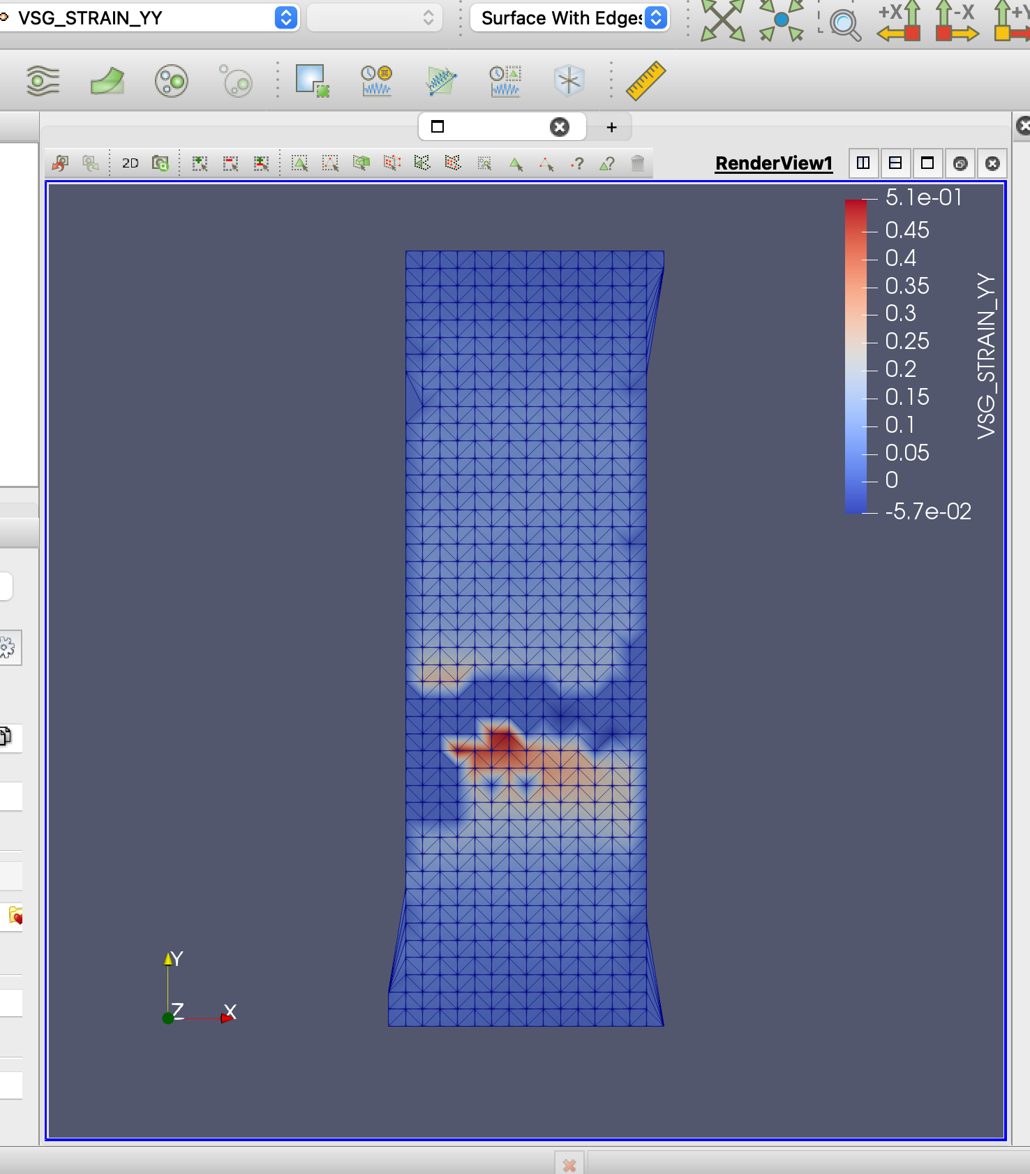
I just started to use Dice to analyze my 2D DIC images. It seems to work fine but I have some problems with the displacement in a tensile test. I set up a subset size for 39 pixels and a step size for 15 pixels. I got a color map for VSG_strain yy, which seems fine (the strain is localized near the crack). However, the displacement of yy direction is very weird. It seems like one part of the sample is under tensile stress (red) but the other one is a compression (blue)? My images were acquired on the tensile test so I think there is only tensile stress no compression. I repeated several times and with a smaller subset and step size but I still got a similar result. Does anyone have any idea why this happen? (the stress is applied along yy direction)
Also, I have a question about how the VSG_strain is calculated is it the displacement in yy / gauge length(I set up 45 pixels).
Thanks a lot,
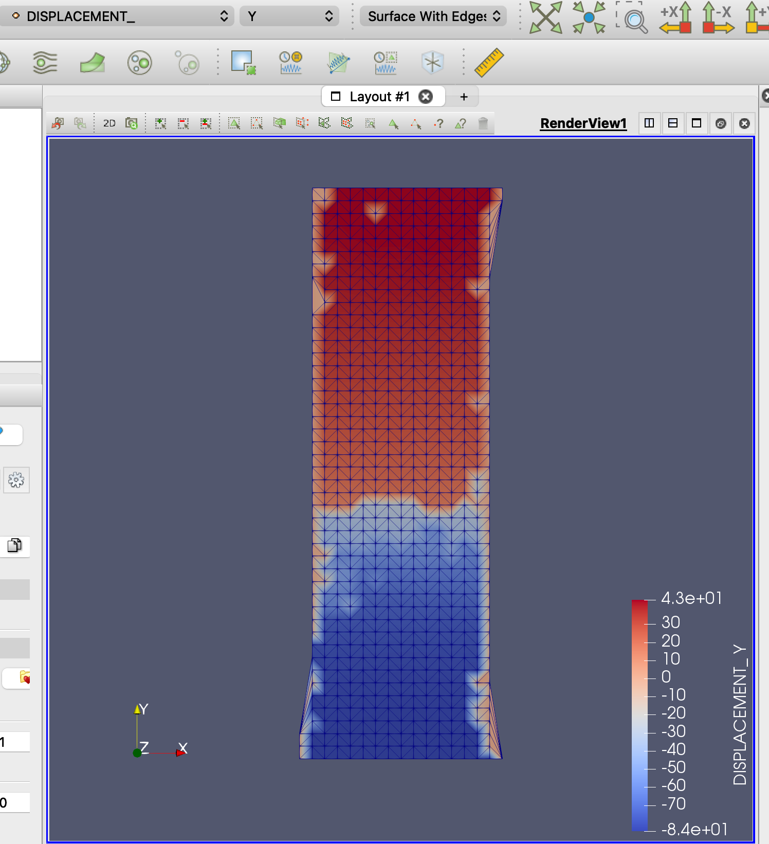
I think your displacement result is not weird. Upper half went upwards, bottom half went downwards during the tensile test.
Thanks for the explanation but the lower part of my grip is fix only the upper grip goes up during the tensile test is that still the same case? sorry, I another dump question. if I want to calculate the engineering strain of the sample is that right that I use the value of the red deduct by the value to the blue and divide the pixel of the gauge length?
My gauge length is larger than the maximum limit I can set in DICE (more than 150 pixel)
Here is a helpful report that explains how the strain is calculated when using the virtual strain gauge: https://github.com/dicengine/dice/blob/master/doc/reports/VirtualStrainGauge.pdf
A couple of other items to note:
- In 2D the y-axis is down which may be the opposite of your experiment
- Your step size is rather large. I would recommend 5px or less
- A step size of 15 with a VSG window size of 150 will lead to overly smoothed strains. I would recommend doing a strain gauge size study where you fix the step size at 5px and gradually increase the VSG window size from 15px to 50px to see what the effect is on the strain profile.
- I'm not sure what your experimental setup is, but it's common for even the "fixed" side of the tensile bar to settle while the load is ramping up, which might be where the displacement at the fixed grip is coming from. Since the displacements are on the order of 40 or 80 pixels you could easily verify if the "fixed" side of your grips are moving or if the sample is slipping in the grip by comparing the two images visually.