esptracker
 esptracker copied to clipboard
Let's try figuring out the data stream.
I've been putting dumps here: https://drive.google.com/drive/folders/1iN0vuhsRMY6tCWZOCC9F4SSBbT9ljmq7?usp=sharing
NOTE DO NOT USE fx3_100MHz_DataCap.dat.tar.gz The data is bad!
Histogram (from 100 MHz FX3 data):

vvv C Program for analyzing the FX3 dump. analyze.txt
Current ideas/questions: (1) Supersoaker: what if it's a CDMA stream, or other stream of pseudorandom data that specifically prevents repeated codes or subcodes and encodes the position of the rotor. (2) Why do my charts show a peak at more than 2 codes? (3) Coding is probably something "like" Manchester. Spread around 6 MHz.
Hint from Alan:
The modulation is quite simple, but sensor group delay might be confusing you a little. Best to probe the laser drive directly if you are completely lost. The data rate is 6 Mbps and the modulation is basically 3/6 MHz FSK, but it includes a pi phase shift on zeros to ensure a minimum frequency. The base station console might give you some hints about what the bitstream is. It is not framed or packetised in any way, so you won't really be helped by capturing more than a few tens of bits. That after all is the entire idea... Or maybe you will... If you can't work out what it is you will need all of it from one sync event, to the next one. Oh and OOTX isn't dead, it just got slower.
Hints we got from Ben:
Ben Jackson	I don't like popcorn but I am baking bread
Ben Jackson	50rpm
Ben Jackson	Charles should make a sampling camera to do ultra-high speed photography of repetitive stuff
Ben Jackson	licensees don't know either
Ben Jackson	yes, that's fine
Ben Jackson	the datasheet has the timings
Ben Jackson	yes, for how to configure the chip
Ben Jackson	the config word isn't that interesting. it's just a way to make adjustments to the chip after the fab. so you would need to know lots of internal details to know what the bits do
Ben Jackson	instead of making a bunch of variants of the chip
Ben Jackson	but once you figure out what it should be, the other values aren't that interesting anymore
Ben Jackson	I think there are updates coming, but I don't know if that's in the update
Ben Jackson	FYI @CNLohr that capture doesn't look right to me
Ben Jackson	it's hard to look at raw analog photodiode signals
Ben Jackson	you need an amplified photodiode with more bw
Ben Jackson	@CNLohr that was re the chat
Ben Jackson	@CNLohr how fast is the ESP sampling?
Ben Jackson	did you look at the datasheet? it should tell you the possible BW of what possible input signals it can process
Ben Jackson	you should probably move the base and the sensor farther apart
Ben Jackson	@MobiusHorizons good idea
Ben Jackson	they don't communicate with each other
Ben Jackson	they're blue while spinning up
Ben Jackson	it is easy to block 2.0 without the blinker
Ben Jackson	there's no clock pin
Ben Jackson	@CNLohr are you sure you powered up and configured the sensor properly?
Ben Jackson	that can make it tricky to just measure the output
Ben Jackson	b/c you still need active config
Ben Jackson	you could have glitched it into sleep mode
Ben Jackson	wait, are you reloading the ESP on every run?
Ben Jackson	and each run it tries to configure the already-configured sensor?
Ben Jackson	@CNLohr beep
Ben Jackson	after you configure the sensor it's in a different mode
Ben Jackson	the initialization sequence won't work then
Ben Jackson	don't drive the D/E lines again after config or you will do unpredictable things
Ben Jackson	so power cycle, send config sequence, D/E go hi-Z and stay hi-Z as long as you want to use it
Ben Jackson	if you have to drive those during a reload you should powercycle the sensor
Ben Jackson	that looks about right for config
Ben Jackson	you sure you are loading those bits in the right order?
Ben Jackson	that looks potentially right
Ben Jackson	he changed TS4231s
Ben Jackson	where it the sensor in front of the base?
Ben Jackson	measure the env timings
Ben Jackson	you probalby have a local reflection
Ben Jackson	a shiny bit right near the sensor
Ben Jackson	like a connector
Ben Jackson	no SUPER local
Ben Jackson	like on the board with the sensor
Ben Jackson	or just move the base way farther away
Ben Jackson	yeah black gaffer tape isn't great for IR
Ben Jackson	sharpie is also terrible in ir
Ben Jackson	the first step to blocking IR is to realize your intuition for what color or transparency things are in IR is shit
Ben Jackson	for not reflecting we have some special matte black optical tape that's black in IR
Ben Jackson	and for blocking transmission you really need foil backed tape
Max Bambusman	@Ben Jackson aluminium duct tape?
Ben Jackson	that will definitely block it
Ben Jackson	but then it's a mirror
Ben Jackson	the tape we use has foil lining but it's black on the outside
Ben Jackson	blue painters tape is almost entirely transparent in IR, fyi
Ben Jackson	@Naters305 it's kind of like interviewing 😉
Naters305	Haha Nice @Ben Jackson
Ben Jackson	I'm going to laugh so hard when you figure out what this bitstream is
Ben Jackson	understanding the bits should be straightforward
Ben Jackson	or rather demodulating them
Ben Jackson	but figuring out what they are might be a crueler challenge than the old wireless protocol
Ben Jackson	@Peter S. Hollander email the VR licensing email (include your account name if it's not obvious) and I can send you some
Ben Jackson	What will his chat thing do if 我说汉语
Ben Jackson	it doesn't like emoticons
Ben Jackson	oh cool it beeps
Ben Jackson	this is super handy
Ben Jackson	unicode characters made your terminal beep
Ben Jackson	they stop transmitting when the motor control loop goes out of spec
Ben Jackson	so in theory if you spun the outside at -50rpm very constantly it would work
Ben Jackson	but your outside motor control loop would need to hold about 200ppm tolerance
Ben Jackson	yeah, I never thought about how hard this would be to reverse engineer from snippets
Ben Jackson	interesting idea
Ben Jackson	or point it into an integrating sphere
Ben Jackson	@CNLohr you didn't forget about power cycling if you want to reconfigure, right?
Ben Jackson	you should just power it with a fet so you can toggle it in the boot sequence
Ben Jackson	@MobiusHorizons the shape of a flashlight beam reflector has the properties you want (i.e. it kind of collimates light)
MobiusHorizons	@Ben Jackson that's pretty much what I was thinking
Ben Jackson	what, you don't want to build an integrating sphere?
Ben Jackson	I love the juxtaposition of how clever an idea that is vs how much it will not help you at all :)
Ben Jackson	how much of a hint do you want
Ben Jackson	the wall would work
Ben Jackson	oh, no, the wall will be more useful
Ben Jackson	wall is strictly a good idea and an improvement over short captures
Ben Jackson	and you will easily figure out 1s vs 0s
Ben Jackson	right
Ben Jackson	I mean having a longer sequence of bits won't help you
Ben Jackson	😃 😃 :)
Ben Jackson	so @Peter S. Hollander has decided to start cutting off his leg with the saw ;-)
Max Bambusman	@Ben Jackson how much do you/steam want the vive to be reverse engineered?
Ben Jackson	when I designed it originally I started by capturing with saleae and decoding w/ python
Ben Jackson	it will export to CSV
Ben Jackson	then I wrote a saleae plugin to demodulate which is fun
Ben Jackson	you typo'd 6MHz as 600kHz at some point
Ben Jackson	the saleae protocol decoders are asynchronous and run in another thread
Ben Jackson	so there can be weird latency
Ben Jackson	I've never tried to use the manchester module
Ben Jackson	it probably would want 6Mhz differential manchester
Ben Jackson	you sure that's not decoding?
Ben Jackson	hmm
Ben Jackson	silicone labs
Ben Jackson	hmmmm
Ben Jackson	try differential manchester, 6MHz, one bit per transfer
Ben Jackson	I wonder if that would work
Ben Jackson	I could find a capture and test
Ben Jackson	maybe it wants 3?
Ben Jackson	does it want 12?
Ben Jackson	it does
Ben Jackson	@CNLohr turn off your unused channels to capture
Ben Jackson	time to 也说汉语
pacccer	@Ben Jackson do we need a higher sample rate?
Ben Jackson	@pacccer I just realized when he was exporting that he had all channels on
Ben Jackson	not sure where he captured
Ben Jackson	@Jernej Jakob right
Ben Jackson	note that the laser line comes out perpendicular to the stripes you see on the lens
Ben Jackson	well you can't take it apart because it's impossible to take apart
Ben Jackson	I'm waiting for ifixit to give it a -1 on the servicability scale
Ben Jackson	1004 is the start of all of our model numbers
Ben Jackson	only for management
Ben Jackson	@CNLohr turn off the unused saleae channels
Ben Jackson	that will unlock higher bw options
Ben Jackson	ohhh non-pro
Ben Jackson	turns out you can tell if your supply chain is compromised if FTDI makes their drivers fail on those devices
Ben Jackson	well if FTDI found out that your devices included counterfeit chips they could sue to prevent you from importing them
Ben Jackson	?
Ben Jackson	I don't care about FTDI
Ben Jackson	what was the capture frequency?
Ben Jackson	that's a good choice
Ben Jackson	I feel like you could get something out of 24MHz the way you're capturing
Ben Jackson	one thing to consider: how would you modulate this if you were doing it?
Ben Jackson	does it make sense if 1's are \"long\" and 0's are \"short\"? that's not a constant bitrate
Ben Jackson	sure, but that's partly down to how you analyzed it
Ben Jackson	your analysis method *adds* phase noise
Ben Jackson	because you add in all phase noise in every edge
Ben Jackson	man this is serious deja vu for me
Ben Jackson	you really want some mulitple of 6 or better 12 or your life is going to be even harder
Ben Jackson	I used 500 :)
Ben Jackson	going to have to go soon
Ben Jackson	if you want to request any specific hints before, now's the time
Ben Jackson	I want to see your reaction when you figure it out, but I think it might take a few more streams...
Ben Jackson	your analysis with your eyes just scrolling along was good
Ben Jackson	your question about bit stuffing already includes an incorrect assumption
Ben Jackson	so the answer is \"mu\"
Ben Jackson	yes
Ben Jackson	although it's DC balanced regardless
Ben Jackson	he's right about \"mu\"
Ben Jackson	the bitstream AND the encoding are both dc balanced
Ben Jackson	you kind of asked about one
Ben Jackson	re: bit stuffing
(I was talking about something ABOUT the signal just naturally works out to make it work out to be right)
Ben Jackson	yes
Ben Jackson	YES
Ben Jackson	oh man you're so close :)
Ben Jackson	got to go, catch up with you all later
Internal pics of the lighthouse:
https://drive.google.com/drive/folders/1cRZ3P2-qimd7ccLXDEDPEvQxj6XS1rv1?usp=sharing
Some notes: TP5/TP6 was interesting... Seemed to be a square wave having to do with the rotor.
The data file:
We probed TP2 and TP16, and read them in with my $45 FX3 at 100 MHz, here is the file, 16-bit wide samples, only look at the bottom 4 bits. Basically, you get repeating 16-bit words... The bottom 4 bits are:
LSB  -> The envelope from the TS4231
     1  -> The data line from the TS4231, Lighthouse pointed at TS at about 1.5 feet away.
     2  -> TP2  (DIRECTLY from the lighthouse)
 MSB -> TP16
Issue https://github.com/cnlohr/esptracker/issues/2 contains additional information about opening the Lighthouse 2.0
In terms of spotting repetition/framing in the data - it might be worth looking at TP2 bit, perform a rolling average (to remove sampling variance and covert to greyscale) and then plot it as various width images.
At some image width(s) the image should (mostly) consist of vertical lines where the sync pattern is.

Don't know ;-) Plotting more of the data shows sections of 'all 1s' so there is some structure. Maybe the TP2 is serialized multi-bit data?

Also had another thought. Whatever the on-beam sync data is, it must be very small/short as the sweeping beam(s) are only on the sensor for a short time. It would be helpful to understand the time info of the sweeps/etc so that we could understand how much the sensor actually sees.
You must have some problem with FX3 streaming, because the recorded file is not continuous. There are jumps in the data stream every 8192 words (= usb transfer size?) Some buffer is overflowing and you are losing data.
Here you can see how the manchester bitstream clock periodically jumps:

Try lower speed (50 or 25MHz should be enough to decode this) or improve USB handling (increase number of overlapped buffers waiting at driver level to be filled, add additional buffer or tweak it in some other way). It's best to test it with signal generator or replace first bytes from each USB frame with counter + timer in fx3, so you can detect any lost frames as well as measure usb latency.
@r2x0t You're right! There are actually a lot of problems with that last data stream. I re-worked the state machine in the FX3 GPIF and fixed a bug in my USB writer. Now, it should be good, all the time.
https://drive.google.com/file/d/1GsVtNzmJHMdrxVYvbTNRq2tcDHcOnCcJ/view?usp=sharing
Try above data set, @mungewell
@cnlohr It's better, but still there is something happening every 16384 bits and I don't think this is in original signal (again same as USB buffer size):
 (used differential display to better see the edges)
But looks like it skips either 1-2 samples or multiple of samples in the length of symbol (much less likely). Doing PLL @ 12MHz recovers good looking manchester coded bitstream. Will continue to dig deeper...
(used differential display to better see the edges)
But looks like it skips either 1-2 samples or multiple of samples in the length of symbol (much less likely). Doing PLL @ 12MHz recovers good looking manchester coded bitstream. Will continue to dig deeper...
@r2x0t Is there any way you can give me your code so we can test against that when I capture the data? I can still try a few different things within the FX3 GPIF engine to avoid any missing samples.
@cnlohr I'm using tool called ViewBin to analyze and visualize the bitstream. But to get same picture as I posted above, just plot the bits as pixels, nothing special. You can do the same with simple code (take bits, differentiate, plot 210 bits/line).
New data is up: https://drive.google.com/drive/folders/1IDDs67zcUPaqEtRxioHnWZO2vxHtX8Zc
It contains two different base ID channels.
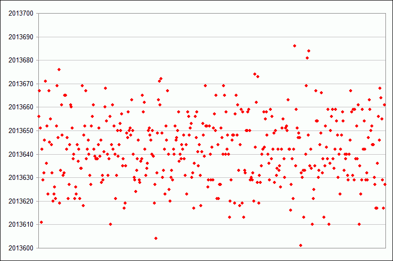
So looking at the bits, I can clearly see data burst for each sweep with long run of "1" bits between. Distance between sweeps is not exactly the same (could be because of FX3 sampling issues?), mean value is 2013642 samples (equals measured sweep rate of 49.6612605 / sec). Here is the graph of distances:
 Demodulated data, manchester decoded, one block per line (split by detecting first "0" bit after a lot of "1"): http://puu.sh/B9ggJ/ef2bc84312.7z
Each data burst is LFSR generated sequence using 20 bit shift register. Two sequences are used, probably to send another slow data signalling channel over it. Also each lighhouse is probably using different set of LFSR sequences, so they can be independently detected. This one is using following taps: x19+x18+x16+x13+x12+x10+x9+x6+x5+x4+x2+1 (D3675 hex) x19+x16+x11+x10+x5+x3+x2+1 (90C2D hex)
So running LFSR finding program on the file above to detect used LFSR in each burst results in following: http://puu.sh/B9fH0/2493f2c09c.txt (using Berlekamp-Massey algorithm on block of 300 bits from each burst)
Note that this is not how it's actually received. Receiver knows the sequences it should look for and it simply have a shift register with taps for each sequence. Bits from taps for every LFSR code are XORed together and if you get run of all zeroes that's >20 bits long, code is detected. I can explain this in more detail or post a code for this if it's not clear.
Anyway resulting "slow" bits from entire file based on two different used LFSRs are:
 1101100110101010
11111100111100010
01001100110111100
11111011110001110
11111100100000000
11111000011000010
10111110001001100
11001110100001110
01100011100001110
11100110011111110
11111111010011000
11000110010001010
11000011010100010
01001011000100010
01001011011101100
11101000111111110
11110010100000110
00111001001000110
11111111111111111
01101010011111111
01011011111111111
00010111101110000
00010111001101101
01111111111111111
00000010
Not sure about coding used here, but arranging it 17 bits/line results in nice column of zeroes, so possibly some 16 bit words? "11111111111111111" might be message start/end synchronization. Also maybe some ECC is used? And no, there is no ASCII text in it, that would be too easy :)
_CHAN_INIT_Data_20180805155528.8.dat use polys 0xD3675,0x90C2D _CHAN_AFTER_BUTTON_Data_20180805170303.8.dat uses 0xB85F3,0xC058B
Here is quick code to do the manchester demodulation and LFSR detection. You can uncomment printfs at various lines to get different outputs (demodulated bits, one burst per line) or LFSRs correlation results. Enjoy!
#include <stdio.h>

int main(int argc, char **argv, char **env)
{
 if (argc<3) {
  printf("[file] [ch]\n");
  return 0;
 }
 FILE *f = fopen(argv[1],"rb");
 int ch = 0;
 sscanf(argv[2],"%d",&ch);

 unsigned char buf[1024];
 int bitmask = 1<<ch;
 double fil[7] = {0};
 double old = 0;
 int dist = 0;

 int taps[] = {0xD3675,0x90C2D, // 8_seconds_8_bit_fixed_Data_20180805134454.8.dat _CHAN_INIT_Data_20180805155528.8.dat
               0xB85F3,0xC058B, // _CHAN_AFTER_BUTTON_Data_20180805170303.8.dat
              };
 const int numtaps = sizeof(taps)/sizeof(taps[0]);
 int detect[numtaps] = {0};
 unsigned int sh = 0;
 while(1) {
  int n = fread(buf,1,sizeof(buf),f);
  int on = 0;
  if (n<1) break;
  for(int i=0;i<n;i++) {
   double in = (buf[i]&bitmask)?1.0:-1.0;
   // Filter it using simple FIR to get rid of some one-sample glitches around edges
   fil[0]=fil[1];fil[1]=fil[2];fil[2]=fil[3];fil[3]=fil[4];fil[4]=fil[5];fil[5]=in;
   double v=fil[0]*0.0280+fil[1]*0.1597+fil[2]*0.2779+fil[3]*0.3396+fil[4]*0.2779+fil[5]*0.1597+fil[6]*0.0280;
   double diff = v*old;
   old = v;
   dist++;
   if (diff<0 && dist>10) { // 10 = little bit more than one symbol length
    if (dist>100) { // long run of same bits between bursts
     int max = 0;
     int maxat = 0;
     for(int j=0;j<numtaps;j++) {
      //printf("%06X:%08d   ",taps[j],detect[j]); // detailed LFSR report
      if (detect[j]>max) {
       max=detect[j];
       maxat=j;
      }
     }
     printf("found LFSR %06X bit %d",taps[maxat],maxat&1); // print best one to get bits
     printf("\n");
     for(int k=0;k<numtaps;k++) detect[k]=0;
    } else {
     int bit = (v>0)?1:0;
     //printf("%d",bit); // print raw demodulated bits if you want that

     sh=(sh<<1)|bit;
     for(int j=0;j<numtaps;j++) {
      unsigned int b = sh&taps[j];
      b^=b>>16;b^=b>>8;b^=b>>4;b^=b>>2;b^=b>>1;b&=1; // parity
      if (!b) detect[j]++; // count zeroes
     }
    }
    dist=0;
   }
  }
 }
 fclose(f);
 return 0;
}
r2x0t
This is awesome work, seriously. :o
When you say "slow" data, do you mean that the Lighthouse switches between the two different LFSRs to send that slower data?
How many sweeps would it take for the receiver to detect each LFSR, or is the data rate fast enough that it would only need ONE sweep to hit a sensor?
I would LOVE to write some quick Verilog code to demodulate this in realtime (from a sensor).
I don't have an original HTC Vive though, only a Rift DK1 and DK2, but it would be interesting to see how hard it would be to do the logic for this.
Are you saying that the shift register in the receiver would just be shifting in the data from the sensor constantly, then you would just take the taps, XOR them, then that would reproduce the "slow" data if you detected a run of bits long enough to fill the shift reg and cause "taps XORed == 0" or "taps XORed == 1"?
I'm still trying to get my brain around how many bits each sensor would typically see during a single sweep.
And, how on Earth did you figure this out so quickly? lol Do you work in encryption by any chance?
I assumed on one of the last streams that the Lighthouses were probably just spitting out a pseudo-random number sequence all the time (a bit like GPS), but I don't know how you figured out the LFSR taps so quickly. Great stuff.
@ElectronAsh
When you say "slow" data, do you mean that the Lighthouse switches between the two different LFSRs to send that slower data?
Yes, think of it as form of spread spectrum (DSSS) modulation. Very similar to how navigation data are sent over GPS signal. Now sure what the contents are, but could be anything from lighthouse ID to additional calibration parameters.
How many sweeps would it take for the receiver to detect each LFSR, or is the data rate fast enough that it would only need ONE sweep to hit a sensor?
Now here is the nice part: only very very small part of bitstream is needed for detection. Exactly 2*20 bits of it, so about ~6.666uS. Once detected, you can also calculate timing from start of the sweep with resolution of used modulation (down to one bit step, so ~0.0833uS).
I would LOVE to write some quick Verilog code to demodulate this in realtime (from a sensor).
You can pretty much follow my code. Sample fast, then lowpass filter it to reduce noise a bit (fixedpoint FIR will do, nothing special) then look for zero crossings (differences) and feed that to shift register with various taps. XOR the taps and add results to another shift registers and when one of these is all zeroes, you got the match.
I'm still trying to get my brain around how many bits each sensor would typically see during a single sweep.
Probably quite a lot more than what's needed for detection (based on data rate and timing numbers I wrote above). But it's also important to account for possibly overlapping beams. For that you may need more bits to correlate multiple sequences (just like in CDMA).
And, how on Earth did you figure this out so quickly? lol
I do SIGINT for fun and profit. Don't even have Vive, just seen one of the @cnlohr videos and though this would be a fun signal to look at :)
Ahh, SIGINT makes sense. I thought it was something like that. ;)
Also - I only just woke up, and instantly realised my mistake in how the receiver would know which part of the sweep it's at.
It would know simply by which "step" of the LFSR pattern it shifts into the register, and the LFSR from the LH would start again from 1, or from another known value at the start of each rotor sweep.
Only a tiny movement of the sweep would be needed for the receiver to shift in 20+ bits to do the detection, and work out the rotor angle from that, yep?
Exactly how many permutations are there for each LFSR value? I know it's not just 2^20 (1,048,576), but still a finite amount.
What I don't quite get yet is how the receiver knows from that very small number of bits which LFSR poly it's looking at.
Even with knowing the full table of values for each LFSR, surely there would be some overlap of the same values for each of the two polys?
Or, does the LFSR poly only change per rotor revolution, so the slow data is sent at only around 50 Hz?
Exactly how many permutations are there for each LFSR value? I know it's not just 2^20 (1,048,576), but still a finite amount.
2^(shift_reg_len)-1 so yes, 2^20-1. Data burst is shorter, so code never repeats.
What I don't quite get yet is how the receiver knows from that very small number of bits which LFSR poly it's looking at.
To just detect poly (without detecting actual position in the code) you only need 2*LFSR_len bits. You load the first half to the shift register and then generate next half, comparing (XORing) it with 2nd received half. This will exactly match only if correct taps are used. If you have more bits, you can do this over longer block to get some resiliency against flipped bits (receive errors). If you generalize it, you end up with algorithm I used in my code: feed all received bits through shift register, try all taps you are looking for and compare result with incoming stream.
Even with knowing the full table of values for each LFSR, surely there would be some overlap of the same values for each of the two polys?
This depends on taps/polynomials chosen. Obviously you would pick some that are well orthogonal so cross-correlation between them is as low as possible. As in any CDMA system, there is a trade-off between number of codes and cross-correlation between the codes. And no, keeping list of all bits isn't really needed, that just wastes memory. After you detect the LFSR, you can run the shift register backwards until you reach initial value - and this will give you actual distance from beginning of the code.
Or, does the LFSR poly only change per rotor revolution, so the slow data is sent at only around 50 Hz?
Exactly, it only changes between sweeps, so entire data burst is always entirely same sequence. That's why I said "slow data" - effective rate is 50bps
Ahh, OK. Got it. Thanks. ;)
Yes, changing the LFSR once per rev does make sense. I couldn't see how it would easily differentiate otherwise.
With other sensors being hit, the receiver would be able to do some correlation there as well, so at least it wouldn't always be relying on a decent signal from one sensor.
I'm still wondering about how best to implement this in Verilog, especially the part about matching the poly without storing all the permutation values.
So, would both halves of the longer LFSR have the same taps for each, or would the taps be calculated for the longer (say 40-bit) value?
I guess it wouldn't be too hard to actually run the LFSR backwards after each "ping" is detected, but you could actually just store all the values in a ROM as well. Having said that, it would be quite a large ROM, and wouldn't fit on a typical mid/low-end FPGA. lol
(the largest amount of on-chip memory I have on a dev board is only around 600KB-1MB.)
I'm also wondering about how the LFSR clocking relates to the quoted "6 MHz" or "6 Mbps" data rate (stated by Ben), and the 48 MHz master clock in the LH. (which was stated by somebody on Discord).
Not that it's too important now, as there will be a certain amount of jitter on exactly when the LFSR restarts on each rotor rev anyway, so the data rate itself isn't so important.
The great thing is, the specific timing of the LFSR clock isn't that critical to figuring out the position either, since it's all related to the rotor angle, and how it coincides with the second sweep.
It's intriguing to think about the algorithm used for correlating the two sweep angles, too.
I'm not great with the maths stuff (to say the least), but I can kind of visualise how that would work.
Again though, once it has the angle values for both sweeps, I guess the rest of the algo is pure trig?
I really want to build a LH 2.0 now. lol. I have plenty of lasers (built my own 1 Watt RGB laser, plus a DAC based on the MCP4922, ESP module, and uSD slot), and plenty of spare hard drives to steal the motors from.
I don't yet have any line generating lenses, but it will be a fun project to try.
Just re-reading your other replies, and realising the beauty of this system. :p
I'm just realising how the sensor picks up a kind of "moving window" (literally) of the LFSR, and that they essentially get the resolution down to one clock cycle (or bit width). Genius.
Whoever came up with that at HTC / Valve needs a pay rise. lol
I'm assuming that the LFSR in the receiver (for each sensor) would need to "reset" as the first bit of new data arrives at the sensor? That way, it doesn't get confused by bits that are still sat in the LFSR from the previous sweep?
And, that also means that if less than 20 bits are seen at a sensor, it probably just has to throw out that data, and not use it at all?
(I guess you could still capture a smaller number of bits, and have reduced correlation accurary?)
Or, does it ideally need to clock in at least 20 bits to have any meaningful idea of the rotor position?
I wonder what sort of useful info the slow data will be conveying?
I mean, the new Lighthouses don't really have to sync with each-other any more (AFAIK), so I can't see there being a huge amount of info there.
The two main LFSR values (per Lighthouse) probably just correlate directly to the serial number, so perhaps the slow data just contains some of the calibration values?
Sorry, I know I'm rambling, but this is all very interesting.
I'm assuming that the LFSR in the receiver (for each sensor) would need to "reset" as the first bit of new data arrives at the sensor? That way, it doesn't get confused by bits that are still sat in the LFSR from the previous sweep?
Not really, the noise between light bursts will take care of that. Receiver will be picking up noise most of the time, resulting in no correlation (ratio of zeroes and ones is roughly same). When LFSR modulated signal is detected, LFSR matching output will produce all zeroes. Crude ASCII art:
incoming         SHIFT REGISTER
bits       _____________       ____
--------->| | | | | | | . . . .| | |
           ^~^~~~~~~~^~~       ~^~^
    taps   | |       |          | |
  LFSR #1  x-x-------x----------x-x----->
                   XORed together

    taps   | |       |          | |
  LFSR #2  x-x-------x----------x-x-----> when LFSR is correct,
                   XORed together         output will be all 0

                    ....etc....
To detect the run of zeroes, you can do:
- Use it as counter ~reset input, ie. when zero, counter counts up, when one, counter is reset to zero. When over some threshold, you got a match.
- Use counter, but zero means count up, one means count down. Counter value clamped to some min/max limits. Similar to above, but this one can cope with few bit errors as counter will only count down on error, not completely reset.
- Use another shift register, adding all bits in it (think of this as a parallel counter/adder).
When detected, you save the main shift register value and run it back to measure position where you are in the LFSR sequence. All this should be quite easy to implement in FPGA, it's all just bit shifts and basic logic.
I'm also wondering about how the LFSR clocking relates to the quoted "6 MHz"
That matches parameters. It's 12MHz before manchester, 6MHz actual data rate.
Slow data from all files so far:
#1 = 8_seconds_8_bit_fixed_Data_20180805134454.8
#2 = _CHAN_AFTER_BUTTON_Data_20180805170303.8
#3 = _CHAN_INIT_Data_20180805155528.8

#1                    #2                    #3
000000000000000001    000000000000000001    000000000000000001
00101011000000001     00101011000000001     00101011000000001
01001000000000001     01001000000000001     01001000000000001
11010000100011111     11010000100011111     11010000100011111
11010001100100101     11010001100100101     11010001100100101
00000000000000001     00000000000000001     00000000000000001
1111101----------     11111010100110001     11111010100110001
-----------------     11100011101010011     11100011101010011
00010011001010101     00010011001010101     000100110010-----
00000011000011101     00010011000011101     -0001110000011101  dif
10110011001000011     10110011001000011     10110011001000011
00000100001110001     00000100001110001     00000100001110001
00000011011111111     00000011011111111     00000011011111111
00000111100111101     -----------------     00000110100111101
01000001110110011     ----0001110110011     01000001110110011
00110001011110001     00110001011110001     00110001011110001
10011100011110001     10011100011110001     10011100011110001
00011001100000001     00011001100000011     00011001100000001  dif
00000000101100111     00000000101100111     00000000101100111
00111001101110101     00111001101110101     00111001101110101
00111100101011101     00111100101011101     00111100101011101
10110100111011101     10110100111011101     10110100111011101
10110100100010011     10110100100010011     10110100100010011
00010111000000001     00010111000000001     00010111000000001
00001101011111001     01100111101111011     11000100100000011  dif
11000110110111001     10101011110000011     10101001110110011  dif
Some parts are incomplete because file was too short to contains complete message, had to piece it together. Also poly pair for _CHAN_AFTER_BUTTON_Data_20180805170303.8.dat should be reversed 0xC058B,0xB85F3 so resulting stream isn't inverted (hard to say which way it's correct). Anyway entire slow frame that's repeating seems to be 443 bits = 18 bit sync + 25 words 17 bits each (16 data + 1 sync). Most of the data is static, but there are some differences. I expect to find lighhouse SN or ID there as well as maybe time counter. I marked the changing words "dif" in above listing.
@r2x0t I am still trying to wrap my head around your detection algorithm. This is just mind boggling to me. My life has been haunted by Chapter 6 of my spread spectrum book which starts by "And now we move to the most difficult problem: Synchronization.
It seems to me that it should be easy to get the demanchestration performed on even a slow processor, like an AVR using a LUT, but, I am truly dumbfounded by this magical property of LFSRs, and why it was not covered in that book!
Do you know if there's a name for that algorithm?
Anyway, once matched to a known polynomial, I can't imagine it being too difficult to find the time within the sequence, and thus the position of the rotor. Totally gonna call my bro tonight, he studied combinatorics.
@cnlohr Just look at it purely from bit operations point of view: LFSR is just a sequence of bits where every bit depends on some previous ones that you select (XOR together). That means you can generate new bits as long as you know N previous ones (N = length of the shift register). And if you know N previous bits, you can also generate any next ones and compare them with actually received bits. Now above example is "one shot" detector, but you can turn it into the "streaming" one I described in that ASCII "art" above. Only the XOR of the correct taps will produce all zeroes and all others will have 50/50 statistical chance of being one or zero, thus being insignificant over longer span of bits. I don't think there is any name for this algorithm, it's just a basic use of LFSR properties.
AVR might not be fast enough for this, maybe STM32. It's possible to look for LFSR only every N bits received (ie. shift them into shift register, but look for code every 10 bits) to reduce complexity. This doesn't reduce precision in any way, you just need longer burst of data which might not be an issue (we still don't know how long this typically is... 100 bits? 1000? more?). Obviously FPGAs are the best for this kind of job, as they are realtime by design (as long as you can fit you design and it can run at required clock frequency).
interesting. looks similar to the serato vinyl timecode. i have some questions, though:
- how does this help to determine headset position?
- how do the lighthouses avoid interfering with each other? or do they (avoid it)?
- how does the rotating hardware modulate the light pulses? (this is the the piece i think is going to be the most interesting. and will require more than soldered test points)
@r2x0t I recapped with a different approach inside the FX3. See if it still looks like it's dropping data. Also, this is a much longer cap after I switched to mode0. Hopefully this is helpful. P.S. I hope you saw I dumped a bunch of stuff from the terminal.
https://drive.google.com/file/d/1fhhww43En1hYYqcaIX0AamgWdnw7LMEE/view?usp=sharing
@Spongman
The headset position can be calculated after so many sensors have the rotor position for the two sweeps.
The LFSR sequence repeats on each rotation of the rotor, so the exact point in time that it hits a sensor correlates to a particular angle of the rotor (and the same for the second sweep, where the laser line is at 90-degrees to the first one).
How you actually go about the sensor fusion and maths stuff to calc the position AND rotation of the headset / handset is beyond my knowledge, though. lol
The Lighthouses simply modulate the laser diode directly. The bit pattern just gets reset on each rotor rev. (and also switched between two different LFSR "seed" values on each rotation, for sending ancilliary data at a much slower rate).
No idea how the sensors avoid interference from multiple Lighthouses now, especially since they are no longer synchronised to each-other (like I believe the V1 Lighthouses were.)
I guess it mainly relies on the sensors picking up a chunk of the LFSR sequence, and it also filters out any data that doesn't correlate too well?
Also, even with the LHs not being synchronised (AFAIK), I think the chances of the sweeps from two or more lighthouses hitting the same sensor at the exact same time is still fairly low.
@r2x0t - Thanks for the further explanation, and the ASCII. ;)
I wasn't sure about what you mentioned before and just XOR'ing the taps on the receiver side, but it does make sense now, since the LFSR is always clocking in new bits, and only the correct sequence should cause the XOR output to go Low.
For a zero-run, yep, I would just go for the counter that resets whenever a 1 bit arrives.
The FPGA logic would also need a PLL I'd imagine, to lock onto the stream correctly.
Useless trivia - the SID chip in the C64 uses some LFSR blocks to generate not only the noise output, but for approximating the more logarithmic response of the ADSR ramps etc. It means the registers can be kept much smaller, but the LFSR sequence quite large. ;)
(it then looks for various LFSR pattern matches, then uses that to advance other logic.)
@r2x0t did you get a chance to see if there are still sampling artifacts at 8192 or 16384 boundaries in the last data dump?
@cnlohr It looks perfect now, no issues in latest data file:
 Bit timing is perfect and stable across entire data burst.
Excellent, so the FX3 can do full 100 MHz 16-bit sampling. I smell a cheap-as-dirt SDR coming...