BIGTREETECH-S42B-V1.0
 BIGTREETECH-S42B-V1.0 copied to clipboard
Error in OLED initialization code
In the file oled.c, where the clock divide ration and oscillator frequency are initialized with the 0xD5 command. The parameter in the file is "80", but I think it should be the hex value "0x80". This might address some of the display instability issues.
Interesting finding. Expected for D5h is a 8-bit value representing [3:0] 4-bit "clock divide ratio" and [7:4] 4-bit "Oscillator Freq." 0d80 = 0b 0101 0000 = ~320 kHz clock and divider 1 0x80 = 0b 1000 0000 = ~380 kHz clock and divider 1 (this would be the default setting)
I experienced many display issues before updating the firmware via this repo. But, I still have display issues after 20h printing.
Therefore, I will try to measure PWM frequency of the motor drivers and stay away from the harmonics for the clock+divider setting. I did not find the magic number for the PWM frequency in the source code yet. Maybe someone else has more luck/skill?
adding the relevant datasheet informations from p.43 here:

10.1.16 Set Display Clock Divide Ratio/ Oscillator Frequency (D5h) This command consists of two functions: • Display Clock Divide Ratio (D)(A[3:0]) Set the divide ratio to generate DCLK (Display Clock) from CLK. The divide ratio is from 1 to 16, with reset value = 1. Please refer to section 8.3 for the details relationship of DCLK and CLK. • Oscillator Frequency (A[7:4]) Program the oscillator frequency Fosc that is the source of CLK if CLS pin is pulled high. The 4-bit value results in 16 different frequency settings available as shown below. The default setting is 1000b.
Jan pointed out, that 187.5kHz might be the PWM frequency. https://github.com/bigtreetech/BIGTREETECH-S42B-V1.0/issues/17
Therefore, staying away from 375kHz would be a good idea to get stable communicaiton but the default setting is hitting the first straight harmonic (380kHz +/-).
Hi and sorry to ask this silly quesiton, but is there a description in how to connect the S42B to the computer? I not an expert in programming microcontrollers, but stumbled across the problem you described on two fo my three controll boards I just recieved recently. I will try the 0x80 default setting and everything is already compiled, so I just need the description on the "hardware part" of how to connect the controller...Thks in Advance
sure, no problem @caesar1111 . I explained the hardware setup here https://github.com/bigtreetech/BIGTREETECH-S42B-V1.0/issues/3
It might be better to change the OLED to something 25% faster or slower than 0x80 as this is hitting the PWM frequency as a possible source for interference.
@Quas7 thks a lot, I just order this programmer: https://www.amazon.de/gp/product/B086TWZNMM/ref=ox_sc_act_title_1?smid=A1X7QLRQH87QA3&psc=1 as for the requency.. should I go with the 0d80 you mentioned above? and just to be sure, you mentioned "SWCK, SDO, GND" in your description. In the pinout there is just the SWDO, so I will go with this mapping: S42B pin -> Programmer PIN: SWCK -> SWCLK SWDO -> SWDIO GND -> GND 3.3V -> 3.3V will post as soon as I have the programmer and had a chance to flash the board... my SK-Go² is waiting for some torture tests on the S42B. Spare belts are ready :)
The programmer looks good and even supports the original ST flashing software (not all clones do that).
If you power the board from another source, I recommend not to connect 3.3v (in theory, the stronger voltage source kills the weaker one or just generates heat). SWDIO is correct (Serial Wire Data Input/Output) - it is just named differently on the silk screen due to little space, I think.
I would try the lowest frequency range first with 0x00 (280kHz +/-). This whould be centered somewhere between the harmonics of the PWM. If I find time, I will build a small coil probe and try to measure the actual frequency peaks with an Osci or a nanoVNA.
I run S42b only on my extruders as it keeps the motor very cool compared to just pushing current through it with open-loop stepper drivers. For other drivers I did not see the benefit - if I miss steps, there is something else wrong. And even with S42b the timing will get a hit as the central processing unit still does not know that there was a deviation so there will always be a small artefact in the print. On top, I do not need travel moves beyond 500mm/s and for print moves the hotend is still the speed limiting factor in my setups (did not yet try volcanos though). But enjoy torturing your SK-Go2 and maybe give some feedback, if you actually made anything move faster or more precise than with the stock TMC2209 on 1.5A :)
Interesting discussion. I too can't stand the instability of the OLED screens. They simply aren't useful. I have found that when my printer is powered down and I have the OLED powered through an ST-link or UART, they are super stable. No issues at all.
I actually do have these motors on my y and x axis. I like to do a lot of stripes in my TPU prints, so I'm changing colors a lot. I'm a bit heavy handed and sometimes bump the print head when I am changing colors. Print is over right then and there. Also, I recently got a delta printer. Love it. Changing colors on it is a nightmare. I have about a 50% chance of knocking the print head out of alignment.
I also like to print fast. Sometimes this causes the print head to come out of alignment.
Anyways, I'm hoping these motors fix the problem.
I'm not a programmer and most of the programming vocabulary goes right over my head. I am curious though if you all are having success changing the firmware for S42B. I was able to find something online that showed me how to make VScode/platformio compile as a hex file. I use ST utility to upload the firmware to PCB, but nothing ever seems to change. First of all, the firmware I compile is 85KB while the stock is only 73KB. That seems odd considering I've only been changing the PID values. Secondly, when I use the ST utility to compare the stock firmware to a firmware I've compiled, it is wildly different. Doesn't make much sense to me if I'm only changing a couple of numbers.
The only way I've been able to successfully change the PID values is through the UART connection and using BTT's serial port assistant. That works, but that doesn't have all the options that you all are talking about with the OLED screen issues. Also, while I'm thinking about it, if I change the PID values in the firmware, compile and upload, then check them through the UART connection and BTT's serial port assistant, the PID values are still the same as they were before. It's weird. Nothing changes when I compile a new firmware.
Just thinking, maybe it is easier to enable "advanced pause" in Marlin and do a home-after-change? Normally, the homing precision is better than 0.05mm with standard mechanical endstops (short lever ones). A repeatability test can be enabled in Marlin as well to verify that for Z-probing.
I have also bought last week an ultra cheap delta printer (FLSUN Q5) and I love it as it is really ultrasilent after a few mods (fans, hotend, UART steppers, BMG extruders, etc.) but as it is a bowden I do not touch the print head for changing filaments at all and I installed a TL Y-splitter for automatic 2 color prints. But I have to do more testing this weekend to get some statistics for possible errors of that setup first.
Regarding your flashing issue. I do not get a hex-file after compiling this repository but a binary and this is 30.872 bytes big. That should also be the default for this repository, I think. As nothing changes for you but the upload seems to be valid... without any offence... did you check the time stamp on your hex files after compiling? I just want to make sure, you really flash a freshly compiled hex and not a leftover file from the repo itself. ;)
My binary compiled via vs code + platform.io is located in \firmware\S42BV1.0.pioenvs\BIGTREE_S42B_V1_0\firwmare.bin
And second thing... you do change these initial values in main.c, right?
line 314 to 316:
int16_t kp=30;
int16_t ki=10;
int16_t kd=300;
and it seems, that for the MKS servo42b (very similar product) there are units sold with a controller protection. https://github.com/makerbase-mks/MKS-SERVO42B/issues/17 Maybe, some batches of S42B come also protected in this way?
@Quas7 thks a lot, I just order this programmer: https://www.amazon.de/gp/product/B086TWZNMM/ref=ox_sc_act_title_1?smid=A1X7QLRQH87QA3&psc=1
I just got that one, or one just like it - and am having really mixed luck with it. Some times it'll connect, sometimes it drops. I don't trust this controller and I don't trust the STLink and it's been a LOT of debugging. I'm looking forward to seeing how that goes for you.
The first time I tried programming it powered by the dongle (and DISconnected from the printer by pulling the white cable) it didn't work, and plugged into printer it didn't work until I fed +5V on the 5V line. Today, it only works powered from the dongle and not when powered from the printer.
Perhaps a seperate thread for general programming issues makes sense so as not to clutter firmware issues.
@nhabes79
I use ST utility to upload the firmware to PCB, but nothing ever seems to change. First of all, the firmware I compile is 85KB while the stock is only 73KB. That seems odd considering I've only been changing the PID values. Secondly, when I use the ST utility to compare the stock firmware to a firmware I've compiled, it is wildly different. Doesn't make much sense to me if I'm only changing a couple of numbers.
I was using the same process this morning. My firmware was 30,872 bytes, like the one @Quas7 posted. I couldn't get stuff to upload from VSC/PIO but I can't tell with all my connection issues what's going on. I'm getting .bin files, BTW. I'm also hoping to use this to prevent occasional skips on the Y-axis - I've set the speeds and accels so low it's really effecting my printing.
Are you hand-calculating the checksums? I found a calculator, tried to write a spreadsheet, but I think I'll have to get into VBA or something to get the checksums and was figuring I'd just use the online calculator. :-\
Re: Changing filament: You should be able to do that with just g-code commands, or through the menus, you can set up load and unload procedures where you shouldn't have to tweak the extruder directly, I've got this on both bowden and direct drive units... And even so, I don't knock the head around as long as it's locked in position... Perhaps a Delta would be less stable?
Lastly: I added a block RIGHT after the includes:
//Set gain constants here. OEM defaults are 30/10/200 #define kP_Gain 30 #define kI_Gain 5 #define kD_Gain 200
and edited 314-316 to be: int16_t kp=kP_Gain; //was: 30 int16_t ki=kI_Gain; //was: 10 int16_t kd=kD_Gain; //was: 250
I just don't like scrolling.
@AbeFM I can feel your pain with the programmers. I have various stlink clones, an original stlink v3 and a bag full of converted black magic probes (you can convert a stlink clone or a blue pill board) as well as an original black magic probe. In my experience, all of them work fine but the clones not always at full speed at with all tools (e.g. ST software).
For uploading with stlink clones I noramllyy use st-flash: https://github.com/stlink-org/stlink But you have to install MSYS2 MinGW (linux in windows) to use it.
The problem with the S42B is mainly the PWM output stage, if the board is "enabled" (normally it is active low!). You can try to set motor current = 0, enable active high (stays off, when unconnected) or remove the motor voltage supply from the JST connector.
Quas7 - Funny. I just got the FLSUN QQS. Changed out the board for an SKR 1.4 turbo with 2209s. Loud as can be. Easily my loudest printer and my corexy and cartesian also used to run the same setup and you could barely hear them. I have to learn more mechanically about the delta to see what is causing all the racket. But man, do I ever love the speed of the delta.
I've always used Cura as my slicer. Works good enough for me. I just use its function to pause at a certain layer and move the head away from my print. I manually pull the filament out and change it. I don't touch the print head at all for my delta to do this (bowden setup), but the print head slightly moves almost every time no matter how careful I am. This is what originally got me on the idea of these closed loop setups. I like your idea of advanced pause feature, but I'm afraid I would still run into the same issue. Also realize I'm doing this with TPU. Sometimes I have to push hard to get the new filament pushed into the hotend. It's uncommon for me to bump my CoreXY or cartesian, but it still happens (probably 10-15%). I've already noticed that the closed loop function still works when my printer is paused. I've pushed hard on my print heads for both of those printers and it snaps back into place - waiting patiently for me to change the filament. :) This is obviously a "me" issue. I'm heavy handed and I'm just looking for an extra "crutch" to help me out on these filament changes. Especially once I convert my delta.
I changed something in VS code or something in platformio.... I can't remember. Somehow, I got it to compile into a hex file. I thought I had to do this because the S42B firmware is hex. I didn't know I could compile it as a binary and just use it that way. That would be a lot easier.
Yes. I check the timestamps on my files. lol. That's one of the first things I learned when I first downloaded this software to compile marlin. Learned that the hard way. I'm definitely uploading my latest compiled hex files, but now I'm super curious to try out using binary to see if that works. I'm tired of doing all the checksum calculations using BTT's serial port assistant.
Yes, the lines you mentioned in the firmware (314-316) - those are the ones I've been changing with no luck. Nothing happens. We'll see when I try with making a binary file.
AbeFM
Yes, I've been hand calculating the checksums (just learned what that was the other day). I too thought about making a spreadsheet, but things get more complicated, at least for me and the time I want to spend, when it comes to adding up the negative numbers. And that one took me awhile to figure out (especially the D value if you want to try something above 255). You have to use the negative value (didn't know that was a thing when I first looked at this) for A2 (A0 or A1 for P and I), then add it to 05 and your new value you want to put in for P, I or D. However, it all has to stay in 8 bit form, so the checksum can't be bigger than 2 characters. In that case, you need to split up your new P, I or D value into 8 bit form and add those two numbers separately. Took me way too long to realize that one. I have a feeling though I'm just saying things you all already know. Hexidecimal is all new to me.
The thing you did with setting the gain constants, do I have to do that to change them? I tend to just leave my VScode open to the spot where I want to change. Really no scrolling involved.
Yeah, I figured I could use gcodes to do a color change, but I found a way that works for me. Every time I've tried to setup something via gcode, something goes wrong. Like after a color change the print head will go back to printing but push out another 50mm of plastic first before restarting and thus ruin my print. I could keep trying to go down this route, but I like what I do. For the most part, it is easy. I could try sending the printhead to home to change my filament, but its extremely hard for me to do on my corexy at the home position. The cartesian would be easier, but I guarantee I can still bump it out of place. Most of my color changes go smoothly. Sometimes things just get stuck and I have to force it a bit more to get through the extruder (Hemera on my corexy and bmg on my delta and cartesian). That's usually when I bump it. As for the delta, No matter what, I'm going to bump it. Doesn't matter where I tell it to home.
@nhabes79 You can try to flash my compiled binary from this thread in case you still run into issues with your compiled one. https://github.com/bigtreetech/BIGTREETECH-S42B-V1.0/files/5210515/S42B_fw_P30_I10_D200.zip My default was P30 I10 D250 - I hope, that is also yours. If you need other values to verify, let me know.
And I just noticed, that all this checksum magic is maybe needed because the devs have been aware, that there is an EMI issue for an enabled drive stage. ;)
And regarding the homing thing. The trick would be to home after changing the filament. No matter how hard you bumped it during filament change, it would just resync the coordinates and know where to start printing again. I think, that is one of the advanced pause features of marlin that can be enabled (home after pause or something like that).
In case, you want to temporarely convert your cheap stlink v2 clones to a blackmagic probe: https://github.com/sakana280/stlink-tool Worked for me right out of the box. Powercycling removes the BMP upgrade. To get it working in platform.io: https://docs.platformio.org/en/latest/plus/debug-tools/blackmagic.html
Ok, first of all, I don't know what any of what you said here means:
And I just noticed, that all this checksum magic is maybe needed because the devs have been aware, that there is an EMI issue for an enabled drive stage. ;)
That's unfortunately above my pay grade. I get into the weeds quick when I try to get information out of computer stuff/programming stuff message boards. Very quickly I have no idea what anyone is talking about. I also don't know what a blackmagic probe is or why I would want to convert my ST Link to one. I also don't know what powercycling is that will remove something called a BMP upgrade.
No worries. Maybe someday I'll look up what this all means.
So, the PID values you have in your firmware file are the stock ones. I'm truly amazed that you got that to work. Having my I value above 1 is an imediate failure. Didn't matter what my P or D values were. Have a look at the pictures below. These were all done on my cartesian printer. The one on the left is with TMC 2209s in open loop. The one in the middle is with the S42B closed loop with stock PID values. The print quality is horrendous. The overshoot is super obvious. The layers can't even stack on top of each other. The one on the right is with my PID values that I entered in hand calculating the hex numbers and using the serial port assistant to do so.


Now, here is where it gets interesting. I changed my platformio back to creating bin files instead of hex. I remembered now, you have to make an edit in the main.py file.

Anyway, I went ahead and compiled my own binary file. Ended up being the same size as your binary file. All good. I used STM32 ST-Link utility to flash it to the S42B. It asked me if I wanted to start at a specific address 0x08000000. I have no idea what that means. I just clicked ok. I then checked the PID values in the serial port assistant. Looked weird.
Then I decided to flash your firmware to my S42B and check the PID values in the serial port assistant. This picture below is exactly what I got whether I used your binary firmware or mine.

If this is what you are using, I don't think your I value is 10 either. I think yours is like mine and is set at 1. Why is P at 040 and D at 025? I have no idea. Either way, I'm back to square one and will have to make PID adjustments through the serial port assistant instead flashing firmware.
Unfortunately, all these tests have now completely jacked up one of my S42B boards. I tried to flash back to the stock firmware (the file called ITEM.hex in the S42B files) and now I get this if I try to check my PID values. the motor still works, but I can't read any of the values on my board nor will it allow me to change them. If you have any idea on what I have to do to flash this back to stock so I can use the serial port assistant again, it would be much appreciated. I don't have to go the route of flashing firmware to change my PID values. The serial port assistant was working fine before even if I had to hand calculate the values. I'm fine going back to that.

No problem @nhabes79. Obviously, you do not need a blackmagic probe or anything fency as your clone is working with the ST link software (many stlink v2 clones do not work this way). These PID values are stepper motor specific and I use my S42B only for the extruder where I have naturally a crazy high dampening on the movment (geared extruder and pushing filament). Therefore, my "I" values can stay stock.
I think, the flashing you do is actually not erasing the part where these values are stored.
Maybe it helps if you do a full "chip erase" before flashing?

Hi,
good the read up on the article, since I hit a similar wall while tuning my SK-Go² (corexy) now running the S42B for X and Y:
 . As you can see, the overall quality is not to bad, but:
 I have a severe overshooting on the corners. It does not matter what material (black is PLA, organe is PETG), no matter what temperature, acceleration or print speed. So if you are now telling me that this could be related to the PID setting in the firmware of the S42B, at least this leave me with another thing to check up.
Since I am still waiting for my programmer to arrive, I cant really start the testing, but what would help for a fast feedback is a precompiled firmeware which is adressing the OLED frequency and the PID issue, just to start into the right direction.....
....will come back as soon as I have the programmer...
I have a severe overshooting on the corners. It does not matter what material (black is PLA, organe is PETG), no matter what temperature, acceleration or print speed. So if you are now telling me that this could be related to the PID setting in the firmware of the S42B, at least this leave me with another thing to check up.
Since I am still waiting for my programmer to arrive, I cant really start the testing, but what would help for a fast feedback is a precompiled firmeware which is adressing the OLED frequency and the PID issue, just to start into the right direction.....
....will come back as soon as I have the programmer...
@caesar1111 are you sure, that this is really XY is overshooting and this is not just overextrusion because of low Jerk/Acceleration at corners? This overextrusion is typical for FDM, if there is no linear advance (pressure advance) enabled and calibrated. If you are slowing down at corners the molten plastic is not following a linear characteristic (it is lagging behind) as the mechanics do.
Did you try with "open loop" (switch 3), if you get the same?
@Quas7 its a good point. I didnt have the issue when I was running the printer with 0.9 steppers and TMC2209 for X and Y... but I was also changing to Volcano hotend in the process of migrating.
So LIN_ADVANCE is not switched on so far, but I was playing around with jerk (or nowadays #define JUNCTION_DEVIATION_MM 0.01) and the acceleration:
#define DEFAULT_MAX_ACCELERATION { 2500, 2500, 50, 2500 }
#define DEFAULT_ACCELERATION 2000
#define DEFAULT_RETRACT_ACCELERATION 2500
#define DEFAULT_TRAVEL_ACCELERATION 2500
starting the acceleration at 500 and went up to 2500 but this didnt change anything....
 ....so next stop: enable and tune in linear advance.
Ok, with a volcano this non-linear effect is even more pronounced. BTW, the testcube is maybe not the best object to test for acceleration and jerk as you need some free distances to get to full speed first. TeachingTec goes over the basics well enough, I think: https://www.youtube.com/watch?v=Mnvj6xCzikM&t=933s&ab_channel=TeachingTech https://www.youtube.com/watch?v=rp3r921DBGI&t=123s&ab_channel=TeachingTech
No problem @nhabes79. Obviously, you do not need a blackmagic probe or anything fency as your clone is working with the ST link software (many stlink v2 clones do not work this way). These PID values are stepper motor specific and I use my S42B only for the extruder where I have naturally a crazy high dampening on the movment (geared extruder and pushing filament). Therefore, my "I" values can stay stock.
I think, the flashing you do is actually not erasing the part where these values are stored. Maybe it helps if you do a full "chip erase" before flashing?
Ok, I have to laugh, but that's exactly what I did that has completely messed up my S42B board (full chip erase, then flash with stock ITEM.hex firmware). No idea why. I have some new S42B boards coming in, just a shame I can't adjust this particular one anymore. Everything else on it still works. It still runs the motor fine in my printer, I just can't adjust the PID values now.
@nhabes79
There is one more thing to try as I ran into this for an MKS servo42b recently.
In settings decrease the communication speed to 240kHz and set it to "Software System Reset"

Than check the Option Bytes.

All flags shood look like in this screenshot (readout from a S42B):

Especially the WDG_SW has to be enabled, otherwise it will reboot continously. Also, all pages should have "No Protection". If there is a mark it will show "Write Protection". I think, platform.io will still give you a "success" but the actual write will fail but that might have been only my setup.
To get back to the orignal topic and close this. I tested now several hours with 0x00 instead of 80 (0d80) to get ~270kHz of display com speed and away from the assumed 187kHz(?) motor PWM harmonics.
I do not see any more display glitches and I do not notice any other issues with this.
0d80 = 0b 0101 0000 = ~320 kHz clock and divider 1 0x80 = 0b 1000 0000 = ~380 kHz clock and divider 1 (this would be the default setting) 0x00 = 0b 0000 0000 = ~270 kHz clock and divider 1
I will therefore start a PR for others to test this as well.

@nhabes79 There is one more thing to try as I ran into this for an MKS servo42b recently. In settings decrease the communication speed to 240kHz and set it to "Software System Reset"
Oh, Ah! I didn't know this end could negotiate for slower speeds - totally I'll do that, the 4MHz would rarely, rarely work.
All flags shood look like in this screenshot (readout from a S42B):
Especially the WDG_SW has to be enabled, otherwise it will reboot continously.
And there's a good chance this is at the heart of my rebooting continuously issue. My flags were all messed up, I'll take another look.
Pretty cool about the screen timing. Hasn't been an issue here, but it's a good approach.
@Quas7 Regarding the PWM frequency, I hooked up my scope to the VRef pins of each driver and tested it. It was indeed very close to 187kHz so I can confirm it. Wasn't spot on but could be because the MCU uses the internal clock...
got the programmer as mentioned above.
changed the OLED freq to 0x00 = 0b 0000 0000 = ~270 kHz clock and divider 1 in oled.c
changed the main.c to int16_t kp=30; // caesar: changed from 30 to 30 (no change so far) int16_t ki=5; // caesar: changed from 10 to 5 int16_t kd=200; // caesar: changed from 250 to 200
installed STM32 ST-LINK Utility v4.5.0.exe
updated the programmer:
 with the current firmware:
 changed the target setting:
Connections setting freq ot 240kHz and Reset Mode to System Software Reset
changed the target setting:
Connections setting freq ot 240kHz and Reset Mode to System Software Reset

disconnected the S42B board from the stepper and connected the programmer: S42B pin -> Programmer PIN: SWCK -> SWCLK SWDO -> SWDIO GND -> GND 3.3V -> 3.3V (yes, 3.3 was working for me without any issue)
Erased the chip
And just hit program to upload the S42BV1.0.pioenvs\BIGTREE_S42B_V1_0\firmware.bin which I compiled with visual studio code......
.....I went without any problem. Now I connected my spare newly programmed S42B incl. stepper to the printer and running a static test of the display stability. if that works out for some hrs I will install the stepper and start to do a dynamic test.
So thanks to all for helping me to get so far. I will post if all the test run successful and read up on the best PID setting....
...ok, the OLED shut down on its own after about 8hrs.... but way better than the 30 sec. before flashing. I was retrying with the 0d80 = 0b 0101 0000 = ~320 kHz clock and divider 1 setting.... but while compiling the following error is showing: close_loop\src\Hardware\oled.c:224:15: error: invalid suffix "d80" on integer constant OLED_WR_Byte(0d80,OLED_CMD); so should the value rather be 0x50 to math the binary 0101 0000 which, translated to hex is 50? ...or am I completly wrong?
You probably figured it out by now, but you could use just "80" or "0x50" (which is 80 in decimal), so it should read: OLED_WR_Byte(80,OLED_CMD);
@caesar1111 I would opt for testing 0b 1010 0000 = ~410 kHz clock and divider 1 next. The 0d80 is the default in this repo, if I remember correctly and did not solve it for me.
It could also be, that it is just too fast. So using the divider to get down to 100kHz might be next and should not be an issue as there are no animations running on the display. This would be maybe: 0x02 = 0b 0000 0002 = ~270kHz / 3 = ~90kHz
No success! I was testing the complete frequency spectrum up and down. (0x02 up to 0xF0) and especially with the divider 2 I was doing literally every step possible. And since I have two steppers installed, I did it at two…. No success! Either the display is getting black, the flickering is improving, the lines are shifting of the letters are double size. Whenever I do a static test, everything is fine for some hrs, but as soon as I am printing, the errors occur again. But here is another fact which was not discussed before. In total I have 3 preassembled closed loop board and steppers sets. One running without any issue. The two others currently installed with both issues, but different ones while flashed with the same firmware. So I started think if this is not only related to the closed loop board only, but also to the attached stepper motors???? @ the others experiencing the problem: Are you running a preassembled set or are have you assembled the closed loop board to a stepper of your own? @Quas7: I was even testing your precompiled firmware for the lazy ones. One display went black after 5 min printing, the other one was flickering for 1h and then went black as well…. Now I bought 2 more S42B sets directly from http://www.biqu.equipment/ (not via Aliexpress) and hope for better quality this time. I will keep you posted.
Very interessting and thanks for the testing and feedback!
Could you do one more thing and change the OLED displays around once?
I am quite sure they buy those from various sources and the line termination on them might vary etc. Just to make sure, we do not optimize on the wrong end. ;)
Hi, that was one of the first things I tested with the original firmware. Now I also did it with your "lazy" version. Even the display coming from the one S42B set which is showing no errors is failing on the other sets. So it is either the closed loop board only or the combination of the board with the preassembled stepper motor. I am curious about feedback of the others facing the issue. If they all were using the sets of if this issues also occurs with board assembled to a different stepper (which would mean, it’s a board only problem).
I had always the suspicion that it depends on the motor size and its inductance and on the set max motor current. Slow moves did not kill the OLED but rapids have been very efficient to kill it.
EDIT: I ordered everything to build a small diy H-field probe. I always wanted to do this and I will test this on the board as my first trial on the next weekend, I think.
Been busy this past week and haven’t had time to look at all the new stuff to read! You all are a wealth of knowledge. I’ll try all the suggestions you mentioned tonight, Quas7.
AbeFM, I’ve settled on these values for my CoreXY and my Cartesian.
P 60 I 0 D100
This has worked well for me. Have to be careful with P value, especially with larger prints. I made a test rectangle to fill up 2/3 of my print bed. If you go too low on the P value, it will do an odd looking overshoot. It does the same kind of curved line overshoot as if a CoreXY printer has the wrong belt tension and isn’t perfectly squared.
I is still 1 or 0 for me. Seems to work the best
I messed with D the most. I was looking for the best possible value to remove as much “hum” from these motors. Doesn’t seem to be any perfect values that I can find. The best I could do is take care of any rattles on my printers that the humming from the motors would magnify.
As for print quality, it’s there. It’s just as good as the 2209s with exception to a little bit of salmon skin. However, I have no ghosting problems at all with the S42B. That surprised me as I typically did have some ghosting issues with the 2209s.
I really wonder, if the salmonskin would get less pronounced with a 10bit sine lookup table compared with the 9bit implemented for the stm32 here. Was also a performance discussion at the MKS Servo42b github. The misfittech original uses 12bit (or ever 14?) but has a faster uC as well.
I ran some quick tests with a quickly build H-field probe and a 4€ 30dB RF-amp to see the emission spectrum of the S42B. I am limited to 100kHz (lower limit of current RF-amp) and 63MHz (FFT limit of my Redpitaya Scope). All these results are relative measurments so do NOT consider the dBm as "calibrated" at all. ;) And, before anybody else points it out - yes, I will have to redo this with a battery powered pre-amp. ;P

Background noise free air
100kHz to 10 MHz

100 KHz to 1 MHz
 we see the switching power supply for the RF-amp that couples via DC. I should use a 9V battery here before proceding!
100 kHz to 400 kHz
 And a bit better the RF-amp power supply again. ;)
STM32 under probe, 100kHz to 63 MHz
 At least the main clock is where it should be around 48MHz. So this setup actually seems to work (not calling it anything validated but... okish for a DIY project).
STM32 under probe, 100kHz to 10MHz
 I will have to check against a STM32 F1 with bare minimum code to see, if all these peaks are actually code related. Could these peaks be timer emissions !?
As the noise floor from my supply is too heavy, I will improve this later this weekend, i.e. go buying a stupid 9V battery. But, I see 140kHz and 170kHz peaks already for the stepper drivers. And also very broad peak for the on-board buck converter of the S42B - that might also a possible source for the display issues.
For anybody interessted in dublicating: The setup should be limited by the RF-amp with 100kHz to 2GHz. It is possible to modify the RF-amp with bigger coupling capacitors to RF-in and RF-out (100nF -> 1uF?) to get ~10kHz to maybe 800MHz to make it more usefull for this type of tests. Did not yet check with my NanoVNA what the preamp can actually do as I need some attenuators first to not fry my Nano. ;)
Great work! Would be interesting to see what signals pop up!
Nice H field probe! Is the inner soldered to the outer where the loop closes? How does the RBW work when using the Redpitaya, can you select it or does it automatically adjust depending on the span?
Thanks. I also found a 9V block in a drawer. So, tonight I will start checking in detail.
I build this H-probe with slit/break in ring center and conductor+shield soldered to shield to close the ring.
 I think, with some 3d printed fixture I could get this a bit smaller. The board is just a bit to crowded with connectors to get the probe perfectly placed.
Regarding the redpitaya the standard FFT app should be auto-adjusting the RBW to the span according to the max datapoints it can hold. At least, I did not see a RBW adjustment option yet. But, I did not investigate deeply yet although the informations should be somewhere here: https://redpitaya.readthedocs.io/en/latest/developerGuide/125-14/fastIO.html
There are also other FFT options as market apps available but I did try them yet as these are not compatible to my beta-FPGA image currently running on the pitaya (thats only a matter of 3min download and SD card flashing).
And here the results for 100kHz to 1000kHz with clean 9V battery supply.
free-air Background measurement (on battery quite clean but some faint bursts in low kHz from somewhere, e.g. a fan maybe)

strongest peak around 460kHz and harmonic at 920kHz over the buck converter coil and diode.
 these peaks spread out all over the board... therefore upper limit 450kHz below to get details.
over Allegro stepper driver output stage 100kHz to 450kHz
 Waterfall diagram: lower half motor disabled, upper half enabled
Peaks are around 143, 153, 230(quite broad) and 296kHz
Waterfall diagram: lower half motor disabled, upper half enabled
Peaks are around 143, 153, 230(quite broad) and 296kHz
probe with a loop of a single motor wire (A1?) without load 100kHz to 450kHz
 Waterfall diagram: lower half disalbed motor, upper half enabled
as above but motor "humming" heavily because of bad calibration

as above but motor steady on position

and now the crazy part...
Probe over OLED board seperated with 20cm DuPont wires from the S42B
 Here I will retest with changed frequencies (0x80, 0d80, 0x00, etc.)
And if you compare with above Allegro driver there are even stronger double peaks at the same frequencies around 150kHz
Here I will retest with changed frequencies (0x80, 0d80, 0x00, etc.)
And if you compare with above Allegro driver there are even stronger double peaks at the same frequencies around 150kHz
and probe over the DuPont wires
 These lines are quite busy! Does not supprise me much, that this communication is quite sensitive to RFI.
Maybe an I2C or SPI display would perform better in this environment?
Edit: a little correction. These FFT peaks are likely a result of one stronger square wave like a clock signal. My OLED runs on 0x00 (270kHz) but this is something far below that.
These lines are quite busy! Does not supprise me much, that this communication is quite sensitive to RFI.
Maybe an I2C or SPI display would perform better in this environment?
Edit: a little correction. These FFT peaks are likely a result of one stronger square wave like a clock signal. My OLED runs on 0x00 (270kHz) but this is something far below that.
I would concentrate my testing for the OLED stability now on 240kHz to 280kHz and around 340kHz. But for testing, the motor requires some load to get full current to emit the full RFI.
Its official, BTT has an issue with the quality, at least with the preassembled sets! I now got my two sets directly bought at the BIQU BTT online shop. Packing was intact but plugging in and testing with OLEDs show a drastic result. At one set the display stays only on for about 5 sec. at the other you at least have to move the stepper, but than the display is going black immediately. (And yes, OLED is working since I have at least one out of 5 S42B sets which is ok, so I was able to test all the OLEDs with this one and all OLEDs are fine) I am still waiting for some feedback of someone who was assembling a closed loop board to a stepper of his own and I he was facing the same issues…… I contacted BIQU with a request for help. We will see….. @Quas7 : did you have a chance to find the perfect frequency?
@caesar1111 so far, I had no more issues with 0x00 but I did not test under heavy load yet. I do not think this is production quality but more likely a design issue.
As you have the biggest sample pile currently, you could try one more thing on the worst sample.
Try to attach the OLED with DuPont extension wires or similar to the board like this:
 Or just pull the OLED a bit out of the connector so it has 2mm more distance to the mainboard.
The OLED sits right above the inductance of the buck converter and that one is emitting 460kHz right to the point where the main IC of the OLED sits... maybe it is just a matter of distance between those two components to make it work.
If this does not help, one could add a ferrite bead or choke or even a toroid to the DuPont extension wires:

 https://www.analog.com/en/analog-dialogue/articles/ferrite-beads-demystified.html
These ferrites can normally be retrieved from old bigger switching power supplies (PC ATX or laptop "bricks").
https://www.analog.com/en/analog-dialogue/articles/ferrite-beads-demystified.html
These ferrites can normally be retrieved from old bigger switching power supplies (PC ATX or laptop "bricks").
Just to confirm: I baught 3 pcs of non-kits (only boards) and experienced similar issues with OLED (freezing, black, corrupted fonts, etc.)
2 of them run on NEMA 17 pancake motors as extruders without issues with 0x00. 1 test setup on a 47mm NEMA for debugging - also no issue so far with 0x00.
Maybe I should have done this step before jumping to RFI measurements. ;)
Build a strip-board debugging port for the OLED terminals (next time, move the next upwards connectro away from the 2nd pin row...):

I only show a few pins... they all behave very similiar.
CS Pin motor enabled standby
 50us/div

CS Pin motor under load
 50us/div

D0 Pin motor enabled standby 1us/div

3V3 pin motor enabled standby 20us/div
 Motor under load

Looking at the singals here I did not yet see the event that could kill this link - all fine from my perspective and nothing boarderline. Maybe the 3.3V supply is a bit noisy under load but I do not expect that either to kill the communication.
I will try now different frequencies for the OLED to get an instable setup to debug.
@caesar1111 I assume this was with the stock firmware they came with? Just curious if these new ones behaved the same with the fix (0x00) proposed by Till...
...just flashed the 0x00 firmware and used 10cm wires to put some distance between the board and the OLED... ....one OLED is now running fine, the other one is showing artifacts but is no longer blacking out. So its getting better somehow. I will get some ferrite bead and longer wires.... I will also play with the new arrival with the worst performance and put it on another stepper, just to see if it is still so bad....
So here we are after a 8h print....
at one stepper I have no longer issues. at the other, I got a lineshift after 15 minutes printing
 after the 8hrs print, display was back to artefacts, but did not turn off itself.
 I am now experimenting with different frequencies until I the get ferrite beads delivered. I will aslo try out a 50cm patchcable, so I can place the OLEDs on the frame of my printer...
And talking about stock firmware... with the 20cm patch cable extension, even the stepper with the worst stability (OLED was switching off after 5 secs.) now the display stays on, when the stepper is moved.
I am planning to put all my 5 S42Bs on the printer X,Y, double Z and Extruder...... then I can test all the steppers simultaneously
I am now experimenting with different frequencies until I the get ferrite beads delivered. I will aslo try out a 50cm patchcable, so I can place the OLEDs on the frame of my printer...
And talking about stock firmware... with the 20cm patch cable extension, even the stepper with the worst stability (OLED was switching off after 5 secs.) now the display stays on, when the stepper is moved.
I am planning to put all my 5 S42Bs on the printer X,Y, double Z and Extruder...... then I can test all the steppers simultaneously
....20cm more patchcable, an old magentic stickytape and frequency at 0xA1 did the trick.......so far. Now the OLED is on for 5hrs printing without issues:
 (The last line missing is just on the picture due to the low frequency.)
I will now do some durability testing......
....ah and the BTT serverice contacted me via Messanger. Lets see what the are suggesting.....
.
.
....good news from the testing..... still no failure with the setup, so the problem seems to be solved. I will try to experiment with insulation of the OLED when plugged in, but not expecting to much.
.
.
...bad news from the BTT support. they are playing the waiting game. I will continue to push for some answers.
(The last line missing is just on the picture due to the low frequency.)
I will now do some durability testing......
....ah and the BTT serverice contacted me via Messanger. Lets see what the are suggesting.....
.
.
....good news from the testing..... still no failure with the setup, so the problem seems to be solved. I will try to experiment with insulation of the OLED when plugged in, but not expecting to much.
.
.
...bad news from the BTT support. they are playing the waiting game. I will continue to push for some answers.
ok, than one permanent solution might be to add a few ferrites or chokes to the display lanes on the PCB for next generation S42B.
I experimented a bit with the OLED frequencies to check, if I can make an unstable setup with wire extensions in place. And it looks like I have been "on the wood way" (German saying for on the wrong track).
F_OSC does not have any impact on the communication speed over the lines and is only changing the refreshrate of the display. Quick verification with a smart phone camera shows this quite nicely for 0x00 vs 0xF0.
On the other hand, checking the D0 (clk) line shows 1.4MHz clock bursts (700ns) and also some higher glitches with uneven spacing (400ns in between) and not 50:50 duty cycle on the clock (more like 40:60 on:off)

The function doing this is just OLED_WR_BYTE in oled.c starting in line 39. It is bit-banging the signals on the pins. So I added a few nop's to the code to make it a bit slower with 1000ns or 1Mhz.
void OLED_WR_Byte(uint8_t dat,uint8_t cmd)
{
	uint8_t i;
    if(cmd)
        OLED_RS_H;
    else
        OLED_RS_L;
	OLED_CS_L;
	for(i=0;i<8;i++)
	{
		OLED_SCLK_L;
		asm volatile ( "nop":: ); //added by Quas7
		asm volatile ( "nop":: ) ;//added by Quas7
		asm volatile ( "nop":: ); //added by Quas7
		asm volatile ( "nop":: ); //added by Quas7
		asm volatile ( "nop":: ); //added by Quas7
		if(dat&0x80)OLED_SDIN_H;
		else OLED_SDIN_L;
		OLED_SCLK_H;
		asm volatile ( "nop":: ); //added by Quas7
		asm volatile ( "nop":: ); //added by Quas7
		asm volatile ( "nop":: ); //added by Quas7
		asm volatile ( "nop":: ); //added by Quas7
		asm volatile ( "nop":: ); //added by Quas7
		dat<<=1;
	}
	OLED_CS_H;
	OLED_RS_H;
}
The result is still the same stable display for me but now hopefully a more robust communication.
 (I am not sure, why there are shorter periods in the clock output, e.g. right next of the markers in the figure above...)
This should mainly help to seperate the data signal via SDIN_H / _L from the rising/falling edge of the clock. And this might also explain, why adding inductance/wire helps a bit with this issue as this should increase the rise and fall times slightly.
EDIT: maybe we should also add a few nop's before sending the data in the for-loop to get CS and RS edges a bit seperated.
@caesar1111 if you still have problems with one of your displays, would you please test this? :)
after 10h enabled on my desk without movment I get a very similar line shift as caesar

Will now increase timings more and check.
I digged into the digital communication now a bit depper and hopefully I can issue a PR next weekend.
The display runs on an SPI 4-wire interface according p.18 of the SSD1306 datasheet (previously posted already). A little background for SPI debugging can be found here: https://hackaday.com/2016/07/01/what-could-go-wrong-spi/
The data (SDIN or D1) is sampled by the OLED for every rising edge of SCLK (D0).
CS and D/C need to be set before SCLK (D0) rises for the first time and SDIN (D1) should be set also before SCLK rises.

I hooked up an open bench logic sniffer to check for any timing issues.

What bothers me a little bit is the clock jumpyness from 1.429MHz to 2MHz (500ns). These jumps always happen when SDIN goes high during clock-low (e.g. 113us here).

It looks like this piece of code is not balanced for clock cycles. The "true" path executes naturally faster than the "false" else-path.
oled.c
		if(dat&0x80)OLED_SDIN_H;   //check, if dat==1 and set SDIN high if true
		else OLED_SDIN_L; //if dat==0 set SDIN low
		OLED_SCLK_H; //rising edge of SCLK
Unfortunatelly, I am quite an OLS-noob in setting simple triggers to catch SPI timing violations in order to get the actual glitch captured. But some violations I catched by brute force:

So, I now just tried to balance the clock cycles for the if-clauses in the bit-banging routine and I will now check, if the OLED stays stable for a few days.
void OLED_WR_Byte(uint8_t dat,uint8_t cmd)  //adding some NOPs to reduce jumpyness of SCLK up to 2MHz and to increase timing margin between SPI signals
{
	uint8_t i;
    if(cmd)
	{
        OLED_RS_H;
	}
    else
        OLED_RS_L;

	OLED_CS_L;

	for(i=0;i<8;i++)
	{
		OLED_SCLK_L;
		if(dat&0x80)
		{
			OLED_SDIN_H;
			asm volatile ( "nop":: ); //compensate for faster timing for dat&0x80 being true
			asm volatile ( "nop":: );
			asm volatile ( "nop":: );
			asm volatile ( "nop":: );
		}
		else OLED_SDIN_L;
		asm volatile ( "nop":: );
		asm volatile ( "nop":: );

		OLED_SCLK_H;   // this rising edge of SCLK triggers the sampling by the OLED SSD1306
	        dat<<=1;   //shift dat one bit
	}

	OLED_CS_H;
	OLED_RS_H;
}
at least on logic level it looks less jumpy this way:

Edit1: Failed after 30min... I will now use 0x00 instead of 0x80 in parallel as the error looks different than before.
Edit2:
Still same issue... will decrease the MHz now again.

Edit3: a bit suprisingly, running the OLED F_OSC as fast as possible with 0xF0 seems more promising than 0x00 or 0x80. Looks like there are two failure modes involved? The buck converter 460kHz and the SPI timing?
You really are digging deep into this! It's great, almost wish my display also gave issues so that I can help with debugging :-)
Something else which could cause the jittery SPI signals are the interrupts. Maybe it's worth also trying to disable Timer6 (running at 10kHz) before the SPI transmission starts and enable it again after (create a critical section). Something like this:
void OLED_WR_Byte(uint8_t dat,uint8_t cmd)
{
	uint8_t i;
	LL_TIM_DisableCounter(TIM6);

    	if(cmd)
        	OLED_RS_H;
    	else
        	OLED_RS_L;

	OLED_CS_L;
	for(i=0;i<8;i++)
	{
		OLED_SCLK_L;
		if(dat&0x80)OLED_SDIN_H;
		else OLED_SDIN_L;
		OLED_SCLK_H;
		dat<<=1;
	}
	OLED_CS_H;
	OLED_RS_H;
	LL_TIM_EnableCounter(TIM6);
}
I quickly fired up my BB60A spectrum analyzer with a H-loop antenna to repeat some of the EMI measurements you made:
10kHz to 2MHz with motor disabled:

10kHz to 2MHz with motor enabled:

The board is powered by 12V (do you also use 12V?) supply and the OLED removed to get in closer to the regulator.
I have only quickly glanced over the plots, like you also mentioned, looks like the regulator runs at about 450kHz to 460kHz.
The noise floor also jumps up really high when the motor output is enabled. The interesting thing is that it's not constant over time, here is the waterfall display:

Can also be seen in zero span mode:
 Looks like its at 300ms intervals.
@swanepoeljan I am honestly impressed by your tool quality level here! :) And great to see, that my setup is somewhat showing at least a similar picture (just with far less resolution). BTW, the redpitaya stays on constant RBW for some reason (other FFT apps available but not tested yet). I just ordered a cheap tinySA to "compensate" for that in the future. ;)
I power my test setup with 12V as well. I also noticed a time dependency of the noise sources but the mech. load dependency was higher so I did not bother looking into it yet. These 300ms could even be linked to the update rate of the display as it looks like the same range.
I got my display now stable for over 16h straight with the fix in the PR - new record. And it really looks like there are two different failures involved that also show two different display errors (shifted lines vs. scaled&disturbed fonts). And I can now also provoke both failure pictures within 30min with F_OSC at certain levels or maybe just too low and also by adding NOPs at the wrong points in the SPI function.
Regarding the idea on disabling interrupts for SPI, I can imagine some random increases in the timing, if an interrupt is fired. I would try this next, if the display shows still issues. On the other hand, we could also just simply reset the display via the RST pin every ~1000ms and forget about it but I did not yet test, what an RST actually does to the display. ;P
@Quas7 : sorry for coming back so late, but I had to get my Gartenzwerg ready for winter..... I finally got my 50cm jumper wires delivered. One stepper which had issues while the display was plugged in is now running flawless even for >24hrs.

The other stepper which was producing the black screen, is still having some issues, just with the 50cm wires, so I added some kind of choke which improved the situation, but is still producing artefacts after a few hrs. printing.

So I plan to design a mount to attach the display to the frame as far away from the stepper as possible. I will also replace the chokes with the the ferrite beads as soon as the shipment arrives. But while I am working on the hardware, I am happy to test different firmware version. Just send me the complete files of the source code where you applied changes (makes it easier for me to compile the test firmware). …since we have no lockdown in Bavaria so far, I will be on a business trip until Thursday, so I can start the testing again on Friday.
@caesar1111 as this is an open-source community there is no time pressure. :) You can grab the optimized code from my fork here: https://github.com/Quas7/BIGTREETECH-S42B-V1.0/tree/OLED_stability_optimization For me, that solved both kind of artefacts I encountered.
Stay safe and healthy on your biz trip! I also expect something partly lockdownish in Hessen/Frankfurt in the coming weeks.
@Quas7: Hi, I was flashing your firmware yesterday didn’t solve the problem either ;( It was looking good first, but then a layer shift happened still showing the changing values, after that the display froze and after about 2h printing the display went black..... Hardware is currently 50cm jumper cable extended with 20cm, so the display is about 60cm away from the board.... I have the two homemade ferrite beads, but somehow its not solving the problem.... without thorough testing it somehow feels that is got a little worse than my old firmware… Next step will be flashing the board again with the original firmware and work with the professional beads….. see if I can solve it with hardware.. If you have other versions of your firmware which I should test, just let me know.
@caesar1111 Thanks for the testing and feedback. I also ran into one interlaced-screen error after approx. 40h sitting on my bench but without any extension cables or beads in place.
I will now just throw in an "init_OLED" every few 100k loops (~20sec) into the main routine to recover from any form of glitch. That is really not the best way of engineering but without having 10 DUTs or a very clever trigger to catch the issue it gets too time consuming to debug.
I updated my fork and the PR with this "fix". You can also change the re-init periode by changing the 100.000 in main.c line 669 to something else (just up to 4mio or change the variable type of OLED_reset_counter to 'long'). Edit: And I changed a few NOPs in the SPI function. So, you also try first to remove the OLED_init in the reset function to test the changed SPI interface only.
I think, the designers at bigtreetech also found this issue during development and could not resolv it as there is the following comment block in main.c ;P
//OLEDOK
//2019-10-21
//2019-10-22
//2019-10-23
//2019-10-28
//2019-10-29
//2019-11-02
//2019-11-04
//2019-11-07
//2019-11-11
//2019-11-15
//2019-11-18
//2019-11-19
//2020-01-03
not even 70 cm cable with a ferrite ring is not solving the problem  still in contact with btt for a solution
@nhabes79 : since you were also experimenting with the PID for a coreXY and the S42Bs installed for XY. have you already some good values to start with? While the BTT guys are letting me wait for solution I will haunt down PID values issues which is resulting in overshooting on edges at my printer. So your values would held while nailing down the correct values for my printer
@caesar1111 the OLED frequency will not solve this - there are other issues as well. I proposed a "fix" for the OLED issue in #20 This re-inits the OLED around every 60 seconds. For what the OLED is normally used, this should be sufficient in my opinion or you reduce the counter to re-init every 10secs but it blanks for 1 second.
@Quas7: Problem is, if the stepper is idle you will loose the values when re-init. and it will not help with the sever cases, where the screen goes black withing 10 sec.... (I have one stepper who does that). Right now, the BTT support is digging down a faulty lot which was shipped out.... at least they asked me for my order number..... this indidcates a quality problem with might not be solvable with a software fix at all.... so currently the only way to get the OLED running without resetting it all the time is to use a long jumper calbe with ferrite beads to get the OLED away and stabilize the signal. To still get a decent display I had to alter the frequency. Problem is, that this altering is indivdual to every stepper since it is a non consistant issue through out the lot I have.... Therefore a many way to tune the frequency would help to dial it in for every controller individually....
@caesar1111 Out of curiosity, have you ever try the TrueStep firmware with the board where the screen goes black within a few seconds? I noticed that the original code that updates the values (Simp, Err, Deg) on the OLED is very slow (due to floating point math, etc.) and was wondering if it could affect the operation of the SPI bit-banging for the OLED. In TrueStep I cleaned it up a bit and would be curious to see if makes any difference.
Alternatively, in the original firmware when you are in the menu does it still go black? Since in the menu it would normally not run the code to calculate these values. Just poking in the dark :-)
Oh ja, something else I wanted to mention. I spoke with a guy that worked in the car industry and he told me that they always had to pull unused pins to ground through a resistor, this was to improved EMC performance. In cases where you can't modify the hardware anymore the recommendation was to make the unused pins outputs or enable the internal pull-up resistors. Maybe this is also something we can try, I will also add it to TrueStep. If it doesn't solve the issue then it's still good practice anyway ;)
so to your first question. Yes, I am currently running your actual version of TrueStep. have to do some more durability testing though...... I will test it with the OLED directly plugged in which is creating the fastest results... and I will try if it makes a difference if you stay in the menu with a static display or if you are in values screen with constantly changing numbers..
what would be interessting is, if the issue also pops up in open-loop mode as well. I suspect that only the closed-loop calculations impact the software SPI implementation.
@Quas7 will test this also.... right now I am running PID at around P70I10D70..... strange but this is closed to the open loop print where I have no overshoot.... ...I will plug in the displays directly, so I have the results within a shorter time ...
@Quas7: Problem is, if the stepper is idle you will loose the values when re-init. and it will not help with the sever cases, where the screen goes black withing 10 sec.... (I have one stepper who does that).
hmm, I think enabling the OLED updates also during idle would not be complicated. But 10sec are really too fast to go for the re-init idea. I use the display only for the menu but now I figured that I did not even test, if the menu items get reloaded without pushing any button. ;)
@Quas7 ...ok here we go with the first test results with the OLED plugged in directly running the TrueStep firmware:
- after less than a minute with starting the print, even the “best” board is going black
- as long as you are displaying a static screen (I used the TrueStep menu) there is not even a flickering of the OLED, even after 10 Minutes of printing. As soon as I start to just move the arrow to indicate the line, the flickering starts…. Exiting the menu and displaying dynamic content results immediately in flickering and after a few sec. in a black OLED. But at the worst case board, the display still freezes and wont recover when you are trying to exit the menu.
- going to open loop is not doing the trick either. The displays will only take a few minutes longer to show problems or go black. Bottom Line: The issue is still not solved, even I you stay in static display or go to open loop! So whatever BTT did to the boards with the issues, it renders them useless for OLED usage…..
@caesar1111 alright. One last shot... could you post a picture of the boards especially the STM32 controller? This behaves so erratic that I almost suspect counterfeit stm32 hardware that is very common on bluepill dev boards etc
 hope that's detailed enough
as I can read:
STM32F
030C8T6
AA094 079
TWN AA 02
ST
So it looks like a https://www.st.com/resource/en/datasheet/stm32f030f4.pdf
hope that's detailed enough
as I can read:
STM32F
030C8T6
AA094 079
TWN AA 02
ST
So it looks like a https://www.st.com/resource/en/datasheet/stm32f030f4.pdf
here one of my boards for comparison.

What I see in a quick comparison:
- no visible rev marking on your STM (mine has a "B")
- way too much solder on D5 for a reflow process (likely hand reworked)
- maybe a small dent(?) next to the STM pins below the U7 label
- what buzzles me most is the inductor with 6R8 (6.8uH) compared to my 220uH inductor EDIT: 22uH
at least the STM32 does not look like an obvious fake part github.com/keirf/Greaseweazle/wiki/STM32-Fakes
@caesar1111 is there any marking on the D5 diode as on mine with SS24? and do you reas S42B v1.0 on the board next to the motor connector?

@swanepoeljan thanks! I had no chance to identify this 6pin DC/DC converter without nowing that only "BN" was the identfier. ;) I will google a bit more around this weekend.
...it really looks like a mix and match thing they do with the components... I can see that no board of ours is alike. Diodes, inductors and ICs are not matching up. I will have a closer look on my other 4 boards and see if I have at least some consistency there…
...here I got another example of a mix and match... some ICs are different...

@Quas7 and @swanepoeljan :
I now checked all my 5 boards..
Bottom line: no more than 2 steppers are alike completely.
The 3 I bought at Aliexpress from BIG TREE TECH CO.,LTD Store are performing a little better. the come with a TWN AA020 code on the STM32 (like Quas7)
The 2 I bought directly form BIQU performing poorly, one so poorly, that after resetting the board, the OLED goes black within 2 secs. they come with ta CHN GQ031 code on the STM32 (like swanepoeljan).
So this means the are definitely using different sources for the components like Taiwanese or Chinese chip manufacturers for the STM32.
And not a nut to crack for you guys. The only board which runs almost flawlessly is the one where the 6R8 inductor is soldered in upside down. This one has a TWN AA020 marking.
 ...just let me know if you need the pics of the other boards as well...
Not sure, if this is a real indicator as ST has multiple packaging and test facilities so there should not be much difference in the controller, if they are genuine.
I would also expect especially during the covid supply chain crysis that some components got 2nd sourced as well. But I see nothing out of the ordinary for industrial or consumer products (this would not fly for med/mil/avionic or automotive, of course).
I still suspect the board layout with the buck converter close to the com header is giving the main issue depending component tolerances. Things like using a hairdryer on the board and testing "hot" (<85C) might change the failure occurence rate for non-failing boards. I can give it a try this weekend.
found our guy (via aliexpress "BNOG" search...): https://datasheet.octopart.com/AOZ1282CI-Alpha-%26-Omega-Semiconductor-datasheet-67314984.pdf

It runs the PWM on 450kHz +/-90kHz as we measured. That range might explain, why different countermeasures work on different boards.
BTW, 220 on the inductance does not mean 220uH it is 22uH. Which also fits perfectly the firs page datasheet example:

And the table fits the selected components... The 68C is a 49.9k and the 20C is 15.8kOhm

I already know from the BTT SKR boards that they really like to use the datasheet examples as best practise.
If I find time this weekend I will heat one of my boards up and check if it fails more rapidly (not heating the OLED!).
Secondly, I will place a simple resistive load on Vout (C2 is the output cap) of the buck and try to drive the coil to saturation and check for the OLED and maybe EMI. It should result in something like this or even worse:

As a hardware fix, it might help to just add a second 0806 capacitor on top of C2 and maybe as well on C5 as the input buffer cap. If the trace from the power header to the other side of the board has a high parasitic resistance, their might be a chance of generating some ringing in the buck converter output, if a sudden load jump happens, e.g. when the STM32 does pull more power for some reason.
found our guy (via aliexpress "BNOG" search...)
Great found! You have a gift for sniffing these kind of things out! ;)
The only board which runs almost flawlessly is the one where the 6R8 inductor is soldered in upside downThe only board which runs almost flawlessly is the one where the 6R8 inductor is soldered in upside down
This is interesting and worth testing out. Maybe polarity of inductor matters noise-wise. I am looking into theory behind this.
of the buck and try to drive the coil to saturation
I believe we are trying to avoid saturation of the core. Even datasheet states saturation is not desired. Larger inductor is easyer to saturate, this might be why larger inductor (22uH) seems to perform worse than 6.8uH, but it is weird since board shouldn't draw THAT much current really. Still worth looking into issue.
Inductor package seems to be NR4018, quick search on mouser: https://eu.mouser.com/_/?keyword=NR4018 shows 22uH parts with rated current of 590mA and 6.8uH pars with rated current 1060mA
I will try to do some calculations according to datasheet of the chip. Just slaping capacitors on board isn't really necesarily solution...
From my calculations both inductor should work fine with DC/DC chip, but note that measurements in datasheets are made at 100kHz going above that frequency does black magic.
The only board which runs almost flawlessly is the one where the 6R8 inductor is soldered in upside down
This is interesting and worth testing out. Maybe polarity of inductor matters noise-wise. I am looking into theory behind this.
I would be very supprised if there is any polarity dependence or more precise winding orientation dependence that would matter for sub GHz noise figures. Not even save to assume that the marking is giving any orientation at all for the winding direction. ;)
Note, that 6R8 is one worst and one best board in our collection. My 220 boards are average with hours of flawless operation.
of the buck and try to drive the coil to saturation
I believe we are trying to avoid saturation of the core. Even datasheet states saturation is not desired. Larger inductor is easyer to saturate, this might be why larger inductor (22uH) seems to perform worse than 6.8uH, but it is weird since board shouldn't draw THAT much current really. Still worth looking into issue.
Correct, saturation is bad. And provoking failures is the key of debugging that is why one would overload or saturate the core here on purpose to find margins for a coarse tolerance calculation.
And clearly, for same form factor or same core geometry more windings saturate the core more easily. The inductor and diode current peaks are also much higher than the average dc current provided at Vout. But, the buck is also implicitly considering the inductance already as for 22uH it has to drive linearly less current into it to keep Vout constant compared to 6.8uH (energy stays almost the same). But driving more current gives more EMI. For smaller inductance one would normally increase the frequency to reduce the peak current again but that is not available for this very basic converter here. On top, a much bigger output cap helps stabilizing in load dump situations to compensate the bucks limited dynamic range given these saturation limits or the input supply limits (see below).
Inductor package seems to be NR4018, quick search on mouser: https://eu.mouser.com/_/?keyword=NR4018 shows 22uH parts with rated current of 590mA and 6.8uH pars with rated current 1060mA
I will try to do some calculations according to datasheet of the chip. Just slaping capacitors on board isn't really necesarily solution...
From my calculations both inductor should work fine with DC/DC chip, but note that measurements in datasheets are made at 100kHz going above that frequency does black magic.
For bad board designs adding caps piggyback is normally the best you can do. ;P For beefier buck converters it is even best practise for 4layer boards with dedicated power planes to have two different form factors for the buffer caps (electrolyte+kerko or 0603+1208) resulting in two different ESR and filter frequency response. In our case the very long almost unbuffered shared (!) supply wiring to this buck input is at least a not perfect condition in case of non steady load scenarios. There is not even a central >10uF cap to buffer the main power rail at the connector. ;)
Found some time to at least follow the supply voltage traces.

The buck converter is at the end of the complete chain. C3 has likely 220nF but it looks like there is only one cermamic buffering the two A4950 that is also a bit far away.
UPDATE:


I just loaded the buck with additional 100Ohm load (+33mA) and my display fails within seconds with skipped lines. Also I start to see random pixels as noise on the OLED. Increasig from 12V supply to 24V supply removed these pixels again - pixels vanish at 15V.
Adding 22Ohm and the display is black and everything gets unstable and I get big spikes on the Vout. Still, the multimeter shows 3.3V. ;)
Stock configuration (yellow Vout, green Vin):

small spikes every 22us on the 3V3 line.
Added 100Ohm to add stable +33mA to Iout and I catched some events that might have killed the communication:
skipped lines:
 tall characters:

I assume, the resulting error just depends on where the SPI communication is hit.
Looking at the LX node (here plotted in green) in parallel does not show a correlation.

Now for possible simple fixes: Adding 10uF parallel to C3 does not help anything (at least not with a THT kerko). As the spikes do not originate from the LX node, I am not sure, if they do not result from something else, e.g. ground level shifting?
Adding a 10uF THT kerko parallel to C2 (output cap) with 100Ohm still in parallel removes all noisy pixels at 12V Vin (noise starts at 11V) and OLED stays stable. I assume, that with removing the 100Ohms we get sufficient margin for stable OLED. Switching from 100Ohm to 47Ohm results in the same OLED issues again even with the added 10uF.
The root cause for the 3V3 spikes is still unknown as the LX node does not show anything. Next would be to measure all 3V3 customers on the PCB or to find something that "ticks" with approx. 22us or around 45.5kHz (any known timers there?) If I do another debug session I will remove L1 and inject a clean 3.3V there to check for the spikes once more. But, that might have to wait a few more days or even weeks.
These are great findings! These seem to me like typical buck converter switching noise case (or perhaps ground line problems, but this will be much harder to diagnose or fix).
Adding 10uF parallel to C3 does not help anything (at least not with a THT kerko).
That again indicates the problem is with switching transients. I think it would benefit smaller low ESR/ESL ceramic capacitors, 10uF THT is just not going to help much in my opinion. Also there is more than enough capacitance from two big electrolitics, 10uF just wont do anything.
Adding a 10uF THT kerko parallel to C2 (output cap) with 100Ohm still in parallel removes all noisy pixels at 12V Vin
Again I would suggest going for smaller capacitance with low ESR, 10nF? I believe good idea would be to measure actual value of C2 since that is pretty much only real output capacitance. If it is small 100nF-ish capacitor, then we do need to add about 10uF, maybe even better 4.7uF tantalum - KEEP ESR/ESL LOW!
If C2 is one of those high capacity tiny capacitor (1-10uF ceramic tiny thing), which I doubt since they seem a bit expensive for putting on chinese mass produced cheap driver, then ESR/ESL is over the roof, then adding small 10nF-ish capacitor in paralel should help.
I did try random electrolitic capacitor I had laying around on OLED 3v3 pins, but of course, it is far away from source of noise and ESR values are not great, so it did not help at all.
Next would be to measure all 3V3 customers on the PCB or to find something that "ticks" with approx. 22us or around 45.5kHz (any known timers there?)
I don't believe it is anything STM operated, since removing all the functionality and code except OLED did not help the issues with OLED. A4950 do use fixed off time of typical 25us but, datasheet does state minimum and maximum times of 16us and 34uS. It should not do much when motors are of though. Might even be some timing thing inside OLED module.
If I do another debug session I will remove L1 and inject a clean 3.3V there to check for the spikes once more. But, that might have to wait a few more days or even weeks.
That will probably eliminate problems, and it probably would be most reliable solution to just throw linear regulator on instead of switching regulator. That is however a bit... hard to expect everyone to modify their boards to that extent. I will try to find some components and experiment with adding capacitors where I believe they are needed.
I would habe piggy packed 0806 but had no 10uF available. You can bet that the output cap is same as in the schematic above. Adding 100nF for the 100ns spikes makes sense.
If C2 is one of those high capacity tiny capacitor (1-10uF ceramic tiny thing), which I doubt since they seem a bit expensive for putting on chinese mass produced cheap driver, then ESR/ESL is over the roof, then adding small 10nF-ish capacitor in paralel should help.
what do you mean with "expensive"? Those 0806 kemet with 10uF are all <1cent parts in 10kpcs, if one does not need high voltage ratings. It is still a factor of 10 above a 100nF kemet but not expensive in my opinion. And it will not help as much as expected to improve ESL,if the design only has long traces everywhere and no power planes.
As can be seen above, a ultra high-ESL THT 10uF kerko already solves the issue with +33mA overloading. Next step would be to replicate this on 6R8 boards with 100Ohm load and 10uF
Solution for non-solder guys is hopefully buying v2. ;)
I hope V2 are better... unfortunately I do not have money to buy a set of V2 drivers so I am stuck with what I have. Thankfully I am very solder guy :D so I will have to do with what I have.
Shall I do some tracing back of connections maybe? it would be painfull job probably.
Can we identify cap that is on the board currently? Maybe measure it in circuit? and complement it with correct complementary capacitor? I should head to the basement on some further research on circuit board topology.
I will try some stuff, but I only have recycled parts at the moment since our country is in a lockdown.
EDIT: IDK WHAT I DID SUDDENLY ONE OF MY DRIVERS IS STABLE?!?! Okaj breatheeee.... So was trying to measure C2 in circuit with multi-meter -> no go. Then, I tried attaching 10uF electrolytic to C2 but I believe I mistakenly soldered 10uF across C4 which would be...bootstrap?... It made things worse firs but when I ripped the improvised capacitor out, it suddenly started working well (with my experimental code test)
@kablek there are not too many connections or components for the 3V3 so tracing should be job of 10 minutes, I hope. But all information is welcome, of course. :) BTW, I am really not sure, if adding 10-100nF on C2 helps much as I suspect the typial 100nF blocking caps on all of the Vcc IC pins. Just noticed, that the TLE5012 with its 12-16mA current consumption does not have the blocking capacitor on the back side - maybe it is attached on the top side or they simply omitted it. ;)
And the STM32 is capable to sink 120mA depending on pin switching. It is by far the biggest customer on the 3V3 rail and I did not yet beep out, if they added the datasheet advised 2x100nf+ 1x4.7uF to its VDDs.
I tried with a VNA and with my trusty multi to measure in circuit the impedance of the 3V3. No chance as the rail is just to leaky. Guess, you made the same conclusion in your edit above.
But, as stated already, BTT loves staying close to the datasheets and it most likely simply a 10uF.
Yes, C4 is the boostrapping cap for the NMOS gate driver.
My first guess would be, that the magic stability is some kind linked to a temperature effect that comes along with the soldering. Maybe you wait 10 min and retest, if it is getting unstable again and maybe just use a hair dryer as I intended before but just did not yet experimented with as I solved it brute force with 10uF already. ;)
Guys, we don't need to trace with multi meter and probing. Open repository file "Item-Pinmap.PDF" in PDF viewer that supports table of contents toolbar (I use SumatraPDF). Open up TOC, all the nets and pins on those nets are in TOC.
And yes C4 is bootstrap capacitor, and C2 is THE ONLY capacitor on 3v3 line!
Also note that there are pads for connections with PC14, PC15, PF0 and PF1 on the board.
I shall do some more investigation here :D
EDIT: also MOSI and MISO for magnetic encoder are connected together.
EDIT 2: There is begining of my reverse engineering altium project in my fork
well I promised you the results of my tortoure testing.... ...after about 15hrs at 100mm/s even the best performing board failed and the OLED went black, the other just froze with artefacts..... and still no news from BTT which promised to send put replacement boards after sending a video to prove the problem...
Similar fix but a bit easier to apply https://youtu.be/6yggQ2xOTqc It gets more likely that not only the OLED gets issues with the bad 3V3 rail design... missing steps likely because of brown out and reboot mid print?
@Quas7 so what capacitor you are suggesting? I will just solder it to the jumper wires for testing, since I am planning to to an angeled bracket for my display anyway.... nad I am waiting on some feedback from the printer facebook page for the PID setting using the S42B on a Z axis.....
normally, one would need 1x 4.7uF "global" +4x 100nF per pin of the STM32. The buck requires at least 10uF itself for stable operation. So, I soldered just one more 10uF accross the output capacitor of the buck converter and got it stable for now.
Therefore, with short leads a 10uF ceramic would be my first guess also for the pin header although @kablek had less success with that but he had only an electroylitc capacitor at hand that is not well suited to filter high frequency noise that we see here. You can add 10uF on both ends of the OLED wire extension as well.
...finally. I got the replacement boards. As you can see, they changed the board layout, but still there are issues with the display, but way better than before (long term testing to be done).
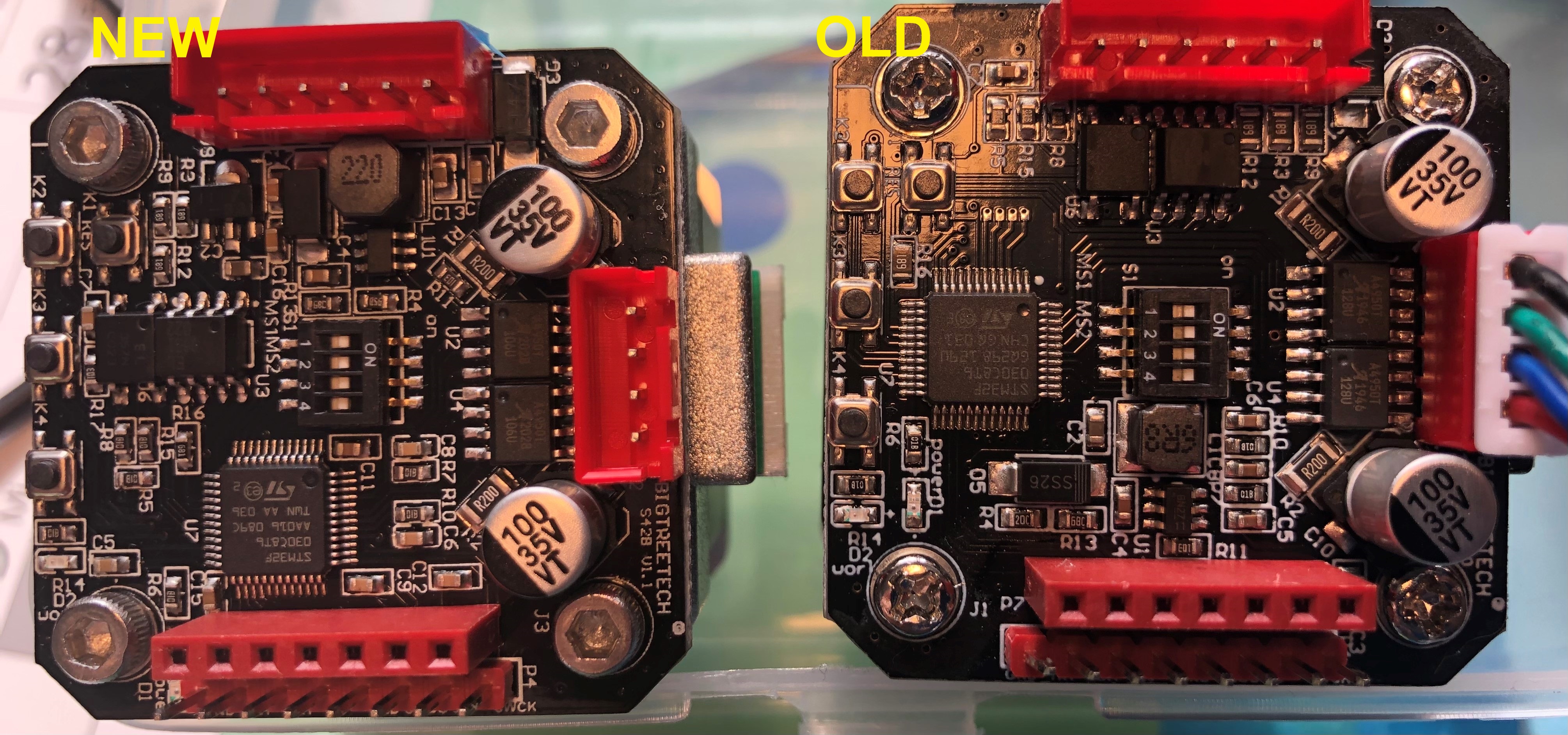
While installing the steppers on a new printer, I had to undergo the PID tuning again and found out that there is a new version of the https://github.com/swanepoeljan/TrueStep out there. Great job on that, makes using the S42B much easier.