Add arcVertex() function to create circles arc using vertices.
Created by: jb4xx
I feel like processing could use a function that easily generate arc circles to construct PShapes.
My proposal would be to use a bezier approximation of a circle and use the already existing bezierVertex() function to create an arc. The argument list of the function could be similar to the one use for the arc() function to keep the same logic.
Here is what the function could look like:
/**
* Use bezierVertex to approximate an arc
* The expected parameters are similar to the one found in the arc() function
* Since it uses bezierVertex to approximate an arc, it must be prefaced with a call to vertex() to set the first anchor point of the arc.
*
* @param  cx        x-coordinate of the center of the arc
* @param  cy        y-coordinate of the center of the arc
* @param  r         radius of the arc
* @param  a1        angle to start the arc, specified in radians
* @param  a2        angle to stop the arc, specified in radians
* @param  rotation  the direction in which to draw the arc. 1 for clockwise. -1 for counterclockwise
*/
void arcVertex(float cx, float cy, float r, float a1, float a2, int rotation) {
  a1 = a1 % TWO_PI;
  a2 = a2 % TWO_PI;
  float angleSpan;
  if (rotation == 1) {
    angleSpan = ((a2 - a1) % TWO_PI + TWO_PI) % TWO_PI;
  } else {
    rotation = -1;
    angleSpan = ((a1 - a2) % TWO_PI + TWO_PI) % TWO_PI;
  }

  int nbOfExtraPts = (int)(angleSpan / HALF_PI);
  float angleStep = angleSpan / (nbOfExtraPts + 1);

  ArrayList<PVector> anchorPts = new ArrayList<PVector>();
  anchorPts.add(new PVector(cx + r * cos(a1), cy + r * sin(a1)));
  for (int i = 0; i < nbOfExtraPts; i++) {
    anchorPts.add(new PVector(cx + r * cos(a1 + rotation * (i + 1) * angleStep), cy + r * sin(a1 + rotation * (i + 1) * angleStep)));
  }
  anchorPts.add(new PVector(cx + r * cos(a2), cy + r * sin(a2)));

  for (int i = 0; i < anchorPts.size() - 1; i++) {
    PVector start = anchorPts.get(i);
    PVector end = anchorPts.get(i + 1);

    float ax = start.x - cx;
    float ay = start.y - cy;

    float bx = end.x - cx;
    float by = end.y - cy;

    float q1 = ax * ax + ay * ay;
    float q2 = q1 + ax * bx + ay * by;
    float k2 = (4/3.0) * (sqrt(2 * q1 * q2) - q2) / (ax * by - ay * bx);

    float x2 = cx + ax - k2 * ay;
    float y2 = cy + ay + k2 * ax;
    float x3 = cx + bx + k2 * by;
    float y3 = cy + by - k2 * bx;

    bezierVertex(x2, y2, x3, y3, end.x, end.y);
  }
}
And here is a possible use case:
final float cx = 300;                   // x-coordinate of the center of the arc
final float cy = 300;                   // y-coordinate of the center of the arc
final float r1 = 150;                   // 1st radius
final float r2 = 250;                   // 2nd radius
final float startAngle = QUARTER_PI;    // Angle at which to start drawing the arc
final float stopAngle = 3 * QUARTER_PI; // Angle at which to stop drawing the arc


void setup() {
 size(600, 600);
 background(20);

 // Define style
 noFill();
 stroke(230);
 strokeWeight(4);

 // Draw the shape
 beginShape();
 vertex(cx + r1 * cos(startAngle), cy + r1 * sin(startAngle));
 arcVertex(cx, cy, r1, startAngle, stopAngle, 1);
 vertex(cx + r2 * cos(stopAngle), cy + r2 * sin(stopAngle));
 arcVertex(cx, cy, r2, stopAngle, startAngle, -1);
 vertex(cx + r1 * cos(startAngle), cy + r1 * sin(startAngle));
 endShape();

}

/**
* Use bezierVertex to approximate an arc
* The expected parameters are similar to the one found in the arc() function
* Since it uses bezierVertex to approximate an arc, it must be prefaced with a call to vertex() to set the first anchor point of the arc.
*
* @param  cx        x-coordinate of the center of the arc
* @param  cy        y-coordinate of the center of the arc
* @param  r         radius of the arc
* @param  a1        angle to start the arc, specified in radians
* @param  a2        angle to stop the arc, specified in radians
* @param  rotation  the direction in which to draw the arc. 1 for clockwise. -1 for counterclockwise
*/
void arcVertex(float cx, float cy, float r, float a1, float a2, int rotation) {
 a1 = a1 % TWO_PI;
 a2 = a2 % TWO_PI;
 float angleSpan;
 if (rotation == 1) {
   angleSpan = ((a2 - a1) % TWO_PI + TWO_PI) % TWO_PI;
 } else {
   rotation = -1;
   angleSpan = ((a1 - a2) % TWO_PI + TWO_PI) % TWO_PI;
 }

 int nbOfExtraPts = (int)(angleSpan / HALF_PI);
 float angleStep = angleSpan / (nbOfExtraPts + 1);

 ArrayList<PVector> anchorPts = new ArrayList<PVector>();
 anchorPts.add(new PVector(cx + r * cos(a1), cy + r * sin(a1)));
 for (int i = 0; i < nbOfExtraPts; i++) {
   anchorPts.add(new PVector(cx + r * cos(a1 + rotation * (i + 1) * angleStep), cy + r * sin(a1 + rotation * (i + 1) * angleStep)));
 }
 anchorPts.add(new PVector(cx + r * cos(a2), cy + r * sin(a2)));

 for (int i = 0; i < anchorPts.size() - 1; i++) {
   PVector start = anchorPts.get(i);
   PVector end = anchorPts.get(i + 1);

   float ax = start.x - cx;
   float ay = start.y - cy;

   float bx = end.x - cx;
   float by = end.y - cy;

   float q1 = ax * ax + ay * ay;
   float q2 = q1 + ax * bx + ay * by;
   float k2 = (4/3.0) * (sqrt(2 * q1 * q2) - q2) / (ax * by - ay * bx);

   float x2 = cx + ax - k2 * ay;
   float y2 = cy + ay + k2 * ax;
   float x3 = cx + bx + k2 * by;
   float y3 = cy + by - k2 * bx;

   bezierVertex(x2, y2, x3, y3, end.x, end.y);
 }
}
I think something like this could be nice.
I used to make arcs by setting a insane strokeWeight, and then draw with a smaller strokeWeight and different radius on top (and using strokeCap square), it can give the same result, but it's a bit hacky I think.
I do however think that the rotation parameter should be removed. If I look at your code:
arcVertex(cx, cy, r1, startAngle, stopAngle, 1);
vertex(...);
arcVertex(cx, cy, r2, stopAngle, startAngle, -1);
Then you already kind of decide the rotation, e.g. does startAngle comes before stopAngle or not.
In other words, if the startAngle is bigger then the stopAngle it's CW else it's CCW.
Also I think creating an ArrayList is overkill, since the default size is 10 and it's a structure mean for growing. You already know the exact size before hand, and in my testing the highest number I got was 3.
So I recommend to just use PVector[] instead.
Also I think angleSpan can be calculated like this, but I didn't check that properly:
angleSpan = abs(a2 - a1) % TWO_PI;
Last but not least, every vertex function in processing allows for a z value as well. And I guess so should arcVertex to keep processing a friendly to use thing.
Thank you @clankill3r for your interest and thank you for the feedbacks.
Regarding your first point, it is important to keep the rotation parameters. Take the following example:
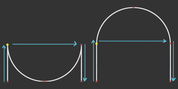
In both cases, the vertices are added following the blue arrows and in both cases, the start angle is PI and the stop angle is 0 and you can't draw it reverse and set the start angle to 0 and the end angle to PI because the start vertex is the yellow one. So the only way to decide witch path to take is to set the rotation either CW or CCW.
I do agree that the ArrayList is overkill and a fixed size array would definitely work. I think the worst case scenario would be 5 vertices if you draw an almost closed circle: the start vertex, the end vertex and 3 control points in the middle.
Regarding the angleSpan, I'm don't think your formula would work since the 2 functions gives different results depending on the rotation. Here's the 2 functions (for a1 = 0), the orange being used for CW rotation and the green one for CCW rotation:
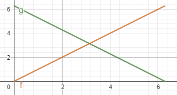
But it can indeed be simplified as followed:
((rotation * (a2 - a1)) % TWO_PI + TWO_PI) % TWO_PI;
With this, we can completely get rid of the if statement.
Finally for the z value, that's a good idea but it needs way more work. Adding a z value for the center of rotation is easy but orienting the rotation in 3D space is a bit more tricky.
Ok good point. I think something inspired by the first image would be good for the documentation page.
Also for the CW and CCW, I think it would be good that in PConstant the following would be added:
int CW = 0;
int CCW = 1;
arcVertex(cx, cy, r1, startAngle, stopAngle, CW);
arcVertex(cx, cy, r1, startAngle, stopAngle, CCW);
Another thought, this is the only vertex function where end point is not defined by a x and y coordinate.
So maybe it is friendly that instead of arcVertex being a void that it returns a PVector representing the end point.
Since the end point is already calculated it basically comes for free to return it.
Demonstrated here:
 PVector v;
 // Draw the shape
 beginShape();
 vertex(cx + r1 * cos(startAngle), cy + r1 * sin(startAngle));
 v = arcVertex(cx, cy, r1, startAngle, stopAngle, 1);
 ellipse(v.x, v.y, 20, 20);
 vertex(cx + r2 * cos(stopAngle), cy + r2 * sin(stopAngle));
 v = arcVertex(cx, cy, r2, stopAngle, startAngle, -1);
 ellipse(v.x, v.y, 20, 20);
 vertex(cx + r1 * cos(startAngle), cy + r1 * sin(startAngle));
 endShape();
About the z coordinate, this one is tough. I can imagine that you just pass the z value threw the parameters, and that that i just the z value being used everywhere. That is better then having no z value at all. But this is also limiting in the possibilities. (It is probably all I ever need).
I have been thinking about the most likely use case I would ever have with needing a z value that has a different value for the end point then the z value at the starting point. And I guess for me that would be drawing a spiral. Now I think there are 2 options that should be considered (can still mean one doesn't make sense at all...):
-
You define a start z and end z and those are the values being used (and interpolate for the in between vertices).
-
You define a start z and end z that would be used for a full arc. Let's say we have:
float startAngle = QUARTER_PI;
float stopAngle = 3 * QUARTER_PI;
float startZ = 0;
float endZ = 15;
That gives us an angleSpan of 1.5707965 (90 degrees).
float t = angleSpan / TWO_PI is 0.25000003.
Now the z value we will end at is endZ * t which is 3.7500005.
Now lets say we want to draw 2 types of springs.
A) This spring has always the same height, but the amount of revolutions can change. B) The height of this spring increases when the amount of revolutions increase.
#1 With option 1, drawing A is easy and B is more work. #2 With option 2, drawing B is easy and A is more work.
Let's take a closer look at the things that require more work: #1
float corrected_endZ = startZ + angleSpan(startAngle, stopAngle) / TWO_PI * abs(endZ - startZ);
arcVertex(cx, cy, r1, startAngle, stopAngle, 1, startZ, corrected_endZ);
#2
float wanted_height = 15;
float t = angleSpan(startAngle, stopAngle);
float corrected_endZ = startZ + (TWO_PI / t) * abs(endZ - startZ);
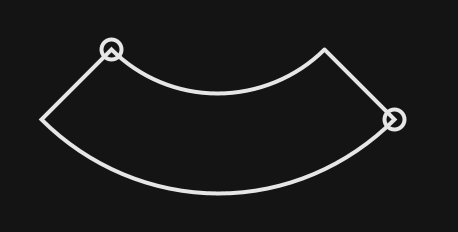
I think it is a bit hard to follow but please put some thought in following what I try to explain here. Personally I think option 1 is the best where the z is given. But the math required to deal with 1/B and 2/A is quite similar. But I can imagine that 95% of the use cases would prefer option 2 for example. The thing is, I would only use those arc's to make gui sliders like:

So it's tough for me to decide what would be best. I think it might be good to implement both for a testing phase. And start making different things using both methods and see which one is most friendly in most of the use cases.
Hi again,
+1 to add PConstant for CW and CCW, that would be more intuitive to use.
I also think it might be a good idea to return the end vertex.
Regarding the 3rd dimension I'm less convinced for 2 reasons:
- In your description, the z value is used only as the world z-axis so it prevents freedom to perform the same effect on other orientations. Of course you could rotate the world before adding you curve but it adds unnecessary complexity if you need to do that every time.
- Your use case is really specific to creating spring like shapes and I don't think that what most of the people would expect from it working in 3D.
The idea behind that function being to approximate arcs (as in part of a circle) using bezier curves, I think it needs to stay just that. So to port it to 3D, the only thing to change is the orientation of the plane on which the arc is drawn meaning that at the end, all points end up on the same plane.
Now the issue with that is that there is no easy way to provide the relevant information:
- If the user provide the (x, y, z) components of the center of the arc, then the plane is not fully constrained since we have defined only 2 points (the start and the center). So in order to fully constrain it, we either need a third point (not colinear with the 2 others) or an angle. I don't find either of those 2 cases really user friendly.
- If now the user were to provide the normal (nx, ny, nz) to the plan on which to draw the arc, the center of the arc still needs to be defined. The only way I can really think of doing this is to provide the 2D coordinates (x, y) of the center in the coordinate system of the plan just created. Again not really user friendly...
For those reasons I don't think the port to 3D would be a good idea.
Yeah I have to agree with you that 3D would not be a good idea.
Ok then the only thing what comes to mind what remains at this point is arcPoint and arcTangent?
Do you mean a function arcPoint to get the coordinate of a point along the arc and arcTagent to get to tangent to the arc on a point along the arc?
Postscript has separate operators "arc" and "arcn" to add CCW and CW arcs to the current path. Cairo, similarly, has cairo_arc() and cairo_arc_negative() functions (see https://www.cairographics.org/manual/cairo-Paths.html#cairo-arc ). But I like your idea of CW and CCW flag constants better.
Do you mean a function
arcPointto get the coordinate of a point along the arc andarcTagentto get to tangent to the arc on a point along the arc?
yes, just to have it inline with the rest of the processing functionality:
https://processing.org/reference/bezierPoint_.html https://processing.org/reference/bezierTangent_.html https://processing.org/reference/curvePoint_.html https://processing.org/reference/curveTangent_.html
And about the CW and CCW, yeah since processing has already things like LEFT, RIGHT, TOP, BOTTOM a parameter seems more inline then having 2 functions. (also in certain cases, having a parameter makes things way easier then having 2 functions cause it can avoid the need of requiring if statements).
In that case I can see 2 options.
The easy way. Since it is a close approximation of a circle, it is quite easy to compute points and tangents based on the circle that is being approximated.
The less easy way. If we consider the previous method to not be precise enough, then we need to use the bezier points to get the real values. I don't think it will be that much more complicated.
Another thing to consider is what would the user expect. The drawing is an approximation but the user wanted to draw a real arc so maybe he is more interested by the values given by taking the circle rather that the one given by the bezier points.
And maybe the delta is so tiny that this discussion is not even needed and whatever the method it would be ok...