Problem: Random shifting of gcode on one axis
Controller Board
Grbl_ESP CNC Controller 4 Axis External Drivers V2.0 https://github.com/bdring/4_Axis_External_Driver
Help From Board Vendor
- [ ] Yes
- [ ] No
- [X] Not Applicable
Machine Description
Chinese CNC6040 with original control board and 0.8kw VFD spindle. FluidNC step/dir outputs are connected to the parallel port input of that control board. The same configuration has been running with grbl for years without issues. Stepper drivers are included in the control board (TB6560AH) Limit switches are NO directly connected to the "4 Axis External Drivers" pcb. NowForever VDF connected to RS485 port of the board. No sd card inserted into the slot. Board running at 24V (yes i made sure the buck converter and input cap can handle that, double and triple checked the schematic to make sure i wouldn't fry anything by doing that)
Input Circuits
NO switches connected to the isolated inputs of the "4 Axis External Drivers V2.0" board. Just a wire and a switch.
Configuration file
Config file:

name: "CNC 6040"
board: "Grbl_ESP32 4 Axis External Drives V2.0"

start:
  must_home: true
  deactivate_parking: true
  check_limits: true

control:
  feed_hold_pin: NO_PIN
  cycle_start_pin: NO_PIN

stepping:
  engine: RMT
  idle_ms: 250
  dir_delay_us: 1
  pulse_us: 2
  disable_delay_us: 1

axes:
  shared_stepper_disable_pin: gpio.13:low
  shared_stepper_reset_pin: NO_PIN

  x:
    steps_per_mm: 320
    max_rate_mm_per_min: 800
    acceleration_mm_per_sec2: 15
    max_travel_mm: 397
    soft_limits: true

    homing:
      cycle: 2
      allow_single_axis: true
      positive_direction: true
      mpos_mm: 0
      seek_mm_per_min: 800.000
      feed_mm_per_min: 25.000
      settle_ms: 250
      seek_scaler: 1.100
      feed_scaler: 1.100

    motor0:
      limit_pos_pin: gpio.34:low
      hard_limits: true
      pulloff_mm: 1
      standard_stepper:
        direction_pin: gpio.2
        step_pin: gpio.0

    motor1:
      null_motor:

  y:
    steps_per_mm: 320
    max_rate_mm_per_min: 800
    acceleration_mm_per_sec2: 15
    max_travel_mm: 583
    soft_limits: true

    homing:
      cycle: 2
      allow_single_axis: true
      positive_direction: false
      mpos_mm: 0
      seek_mm_per_min: 800.000
      feed_mm_per_min: 25.000
      settle_ms: 250
      seek_scaler: 1.100
      feed_scaler: 1.100

    motor0:
      limit_neg_pin: gpio.35:low
      hard_limits: true
      pulloff_mm: 1
      standard_stepper:
        direction_pin: gpio.15:low
        step_pin: gpio.26

    motor1:
      null_motor:

  z:
    steps_per_mm: 320
    max_rate_mm_per_min: 800
    acceleration_mm_per_sec2: 25
    max_travel_mm: 73
    soft_limits: true

    homing:
      cycle: 1
      allow_single_axis: true
      positive_direction: true
      mpos_mm: 0
      seek_mm_per_min: 600.000
      feed_mm_per_min: 25.000
      settle_ms: 250
      seek_scaler: 1.100
      feed_scaler: 1.100

    motor0:
      limit_pos_pin: gpio.36:low
      hard_limits: true
      pulloff_mm: 1
      standard_stepper:
        direction_pin: gpio.33:low
        step_pin: gpio.27

    motor1:
      null_motor:

spi:
  miso_pin: gpio.19
  mosi_pin: gpio.23
  sck_pin: gpio.18

sdcard:
  cs_pin: gpio.5
  card_detect_pin: NO_PIN

coolant:
  flood_pin: NO_PIN
  mist_pin:  gpio.21

probe:
  pin: gpio.32:low:pu
  check_mode_start: true

NowForever:
  uart:
    txd_pin: gpio.17
    rxd_pin: gpio.4
    rts_pin: gpio.16
    baud: 9600
    mode: 8N1
  modbus_id: 1
  tool_num: 0
  speed_map: 0=0% 24000=100%


Output of $CD:
board: Grbl_ESP32 4 Axis External Drives V2.0
name: CNC 6040
meta:
stepping:
  engine: RMT
  idle_ms: 250
  pulse_us: 2
  dir_delay_us: 1
  disable_delay_us: 1
  segments: 12

axes:
  shared_stepper_disable_pin: gpio.13:low
  shared_stepper_reset_pin: NO_PIN
  x:
    steps_per_mm: 320.000
    max_rate_mm_per_min: 800.000
    acceleration_mm_per_sec2: 15.000
    max_travel_mm: 397.000
    soft_limits: true
    homing:
      cycle: 2
      allow_single_axis: true
      positive_direction: true
      mpos_mm: 0.000
      feed_mm_per_min: 25.000
      seek_mm_per_min: 800.000
      settle_ms: 250
      seek_scaler: 1.100
      feed_scaler: 1.100

    motor0:
      limit_neg_pin: NO_PIN
      limit_pos_pin: gpio.34:low
      limit_all_pin: NO_PIN
      hard_limits: true
      pulloff_mm: 1.000
      standard_stepper:
        step_pin: gpio.0
        direction_pin: gpio.2
        disable_pin: NO_PIN

    motor1:
      limit_neg_pin: NO_PIN
      limit_pos_pin: NO_PIN
      limit_all_pin: NO_PIN
      hard_limits: false
      pulloff_mm: 1.000
      null_motor:

  y:
    steps_per_mm: 320.000
    max_rate_mm_per_min: 800.000
    acceleration_mm_per_sec2: 15.000
    max_travel_mm: 583.000
    soft_limits: true
    homing:
      cycle: 2
      allow_single_axis: true
      positive_direction: false
      mpos_mm: 0.000
      feed_mm_per_min: 25.000
      seek_mm_per_min: 800.000
      settle_ms: 250
      seek_scaler: 1.100
      feed_scaler: 1.100

    motor0:
      limit_neg_pin: gpio.35:low
      limit_pos_pin: NO_PIN
      limit_all_pin: NO_PIN
      hard_limits: true
      pulloff_mm: 1.000
      standard_stepper:
        step_pin: gpio.26
        direction_pin: gpio.15:low
        disable_pin: NO_PIN

    motor1:
      limit_neg_pin: NO_PIN
      limit_pos_pin: NO_PIN
      limit_all_pin: NO_PIN
      hard_limits: false
      pulloff_mm: 1.000
      null_motor:

  z:
    steps_per_mm: 320.000
    max_rate_mm_per_min: 800.000
    acceleration_mm_per_sec2: 25.000
    max_travel_mm: 73.000
    soft_limits: true
    homing:
      cycle: 1
      allow_single_axis: true
      positive_direction: true
      mpos_mm: 0.000
      feed_mm_per_min: 25.000
      seek_mm_per_min: 600.000
      settle_ms: 250
      seek_scaler: 1.100
      feed_scaler: 1.100

    motor0:
      limit_neg_pin: NO_PIN
      limit_pos_pin: gpio.36:low
      limit_all_pin: NO_PIN
      hard_limits: true
      pulloff_mm: 1.000
      standard_stepper:
        step_pin: gpio.27
        direction_pin: gpio.33:low
        disable_pin: NO_PIN

    motor1:
      limit_neg_pin: NO_PIN
      limit_pos_pin: NO_PIN
      limit_all_pin: NO_PIN
      hard_limits: false
      pulloff_mm: 1.000
      null_motor:

kinematics:
  Cartesian:

spi:
  miso_pin: gpio.19
  mosi_pin: gpio.23
  sck_pin: gpio.18

sdcard:
  cs_pin: gpio.5
  card_detect_pin: NO_PIN

control:
  safety_door_pin: NO_PIN
  reset_pin: NO_PIN
  feed_hold_pin: NO_PIN
  cycle_start_pin: NO_PIN
  macro0_pin: NO_PIN
  macro1_pin: NO_PIN
  macro2_pin: NO_PIN
  macro3_pin: NO_PIN

coolant:
  flood_pin: NO_PIN
  mist_pin: gpio.21
  delay_ms: 0

probe:
  pin: gpio.32:low:pu
  check_mode_start: true

macros:
  startup_line0:
  startup_line1:
  macro0:
  macro1:
  macro2:
  macro3:

start:
  must_home: true
  deactivate_parking: true
  check_limits: true

parking:
  enable: false
  axis: Z
  target_mpos_mm: -5.000
  rate_mm_per_min: 800.000
  pullout_distance_mm: 5.000
  pullout_rate_mm_per_min: 250.000

user_outputs:
  analog0_pin: NO_PIN
  analog1_pin: NO_PIN
  analog2_pin: NO_PIN
  analog3_pin: NO_PIN
  analog0_hz: 5000
  analog1_hz: 5000
  analog2_hz: 5000
  analog3_hz: 5000
  digital0_pin: NO_PIN
  digital1_pin: NO_PIN
  digital2_pin: NO_PIN
  digital3_pin: NO_PIN

arc_tolerance_mm: 0.002
junction_deviation_mm: 0.010
verbose_errors: false
report_inches: false
enable_parking_override_control: false
use_line_numbers: false
planner_blocks: 16
NowForever:
  uart:
    txd_pin: gpio.17
    rxd_pin: gpio.4
    rts_pin: gpio.16
    cts_pin: NO_PIN
    baud: 9600
    mode: 8N1

  modbus_id: 1
  tool_num: 0
  speed_map: 0=0.000% 24000=100.000%
  off_on_alarm: false
Startup Messages
Will add proper boot messages tomorrow. For now only without being plugged into the board and with no VFD connected. (that's why its complaining about the limits and the VFD)

Resetting MCU
ets Jun  8 2016 00:22:57

rst:0x1 (POWERON_RESET),boot:0x13 (SPI_FAST_FLASH_BOOT)
configsip: 0, SPIWP:0xee
clk_drv:0x00,q_drv:0x00,d_drv:0x00,cs0_drv:0x00,hd_drv:0x00,wp_drv:0x00
mode:DIO, clock div:1
load:0x3fff0030,len:1184
load:0x40078000,len:12812
load:0x40080400,len:3032
entry 0x400805e4

[MSG:INFO: FluidNC v3.6.2]
[MSG:INFO: Compiled with ESP32 SDK:v4.4.1-1-gb8050b365e]
[MSG:INFO: Local filesystem type is spiffs]
[MSG:INFO: Configuration file:config.yaml]
[MSG:DBG: Running after-parse tasks]
[MSG:DBG: Checking configuration]
[MSG:INFO: Machine CNC 6040]
[MSG:INFO: Board Grbl_ESP32 4 Axis External Drives V2.0]
[MSG:INFO: SPI SCK:gpio.18 MOSI:gpio.23 MISO:gpio.19]
[MSG:INFO: SD Card cs_pin:gpio.5 detect:NO_PIN]
[MSG:INFO: Stepping:RMT Pulse:2us Dsbl Delay:1us Dir Delay:1us Idle Delay:250ms]
[MSG:INFO: Axis count 3]
[MSG:INFO: Shared stepper disable gpio.13:low]
[MSG:INFO: Axis X (-397.000,0.000)]
[MSG:INFO:   Motor0]
[MSG:INFO:     standard_stepper Step:gpio.0 Dir:gpio.2 Disable:NO_PIN]
[MSG:INFO:  X Pos Limit gpio.34:low]
[MSG:DBG: Updating  X Pos Limit]
[MSG:DBG:  X Pos Limit 1]
[MSG:INFO:   Motor1]
[MSG:INFO: Axis Y (0.000,583.000)]
[MSG:INFO:   Motor0]
[MSG:INFO:     standard_stepper Step:gpio.26 Dir:gpio.15:low Disable:NO_PIN]
[MSG:INFO:  Y Neg Limit gpio.35:low]
[MSG:DBG: Updating  Y Neg Limit]
[MSG:DBG:  Y Neg Limit 1]
[MSG:INFO:   Motor1]
[MSG:INFO: Axis Z (-73.000,0.000)]
[MSG:INFO:   Motor0]
[MSG:INFO:     standard_stepper Step:gpio.27 Dir:gpio.33:low Disable:NO_PIN]
[MSG:INFO:  Z Pos Limit gpio.36:low]
[MSG:DBG: Updating  Z Pos Limit]
[MSG:DBG:  Z Pos Limit 1]
[MSG:INFO:   Motor1]
[MSG:INFO: Kinematic system: Cartesian]
[MSG:INFO: NowForever Spindle Uart Tx:gpio.17 Rx:gpio.4 RTS:gpio.16 Baud:9600]
[MSG:INFO: Using spindle NowForever]
[MSG:INFO: Mist coolant gpio.21]
[MSG:INFO: Probe Pin: gpio.32:low:pu]
[MSG:INFO: WiFi is disabled]
[MSG:DBG: VFD setState:0 SpindleSpeed:0]
[MSG:DBG: RPM:0 mapped to device units:1073423424]

Grbl 3.6 [FluidNC v3.6.2 (wifi) '$' for help]
[MSG:INFO: Check limits]
[MSG:INFO: '$H'|'$X' to unlock]
[MSG:INFO: VFD RS485 Unresponsive]
User Interface Software
Universal Gcode Platform 20220917
What happened?
Sometimes axis just randomly "shift" while executing gcode.
In this example the X axis shifted towards +X about 2mm.
Other times the Z axis was shifting towards -Z an unknown amount.
This causes parts of the cuts to be misaligned with the rest or travel moves to intersect with the part.
The attached pictures show the result (was repeatable 3x) vs the expected part (ugs preview and camotics simulation)
The misaligned features so far were only "G2" commands as far as i could tell (not 1000% sure though).
Also not sure if that's related or not but after aborting the execution of that file i remember having issues with homing. Some axis would still report an alarm even though as far as i could tell none of the limit switches were triggered. Motor movement while homing a second time was also erratic.


GCode file in question:
Generated using Version: 0.21.30193 (Git) AppImage and grbl post processor with the following options:
--no-show-editor --translate_drill
Other Information
Earlier the same day i cut 3 parts without issues (that included G2 spiral path codes as well, lots of them in fact) without issues. The fourth part failed with the issues described above (didnt notice that yet). After a few hours of the machine and host pc being completely powered down (plugs pulled) i tried to cut the part in the picture. Rebooted and power cycled the machine after the first failure without any effect.
The first thing that jumps out at me is the pulse_us value. That is very short for an optocoupled input, especially if it is being driven from 3.3V instead of 5V. But even if it is a direct input to the TB6560AH chip, it is still way out of spec for the TB6560's CLK (their name for STEP) input. According to https://toshiba.semicon-storage.com/info/docget.jsp?did=11252&prodName=TB6560AHQ :
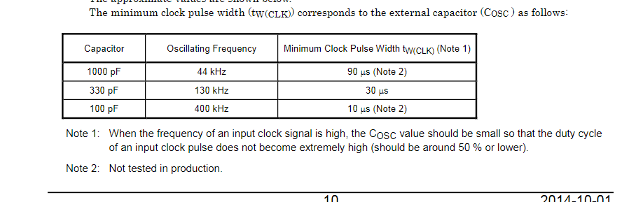
That gives the shortest pulse that is tested in production as 30 us, and maybe you can go down to 10 us with a different value for the oscillator capacitor. Even at 10 us, a 2 us pulse is badly out of spec. It appears that the TB6560 needs about 40 cycles of the oscillator to reliably recognize a step pulse on the CLK input. At the standard oscillator frequency of 130 kHz, a 2 us pulse is less than 1/4 of an OSC clock.
Your max step rate is 320 steps/mm * 800 mm/min / 60 sec/min = 4267 steps/sec, or 234 us/step. At that rate there is no need for a short pulse.
I suspect that the reason it works with grbl-mega is because grbl-mega is either configured for a longer pulse, or maybe it cannot even make shorter pulses. I have seen references that suggest it is limited to about about 30 khz pulsing.
So the first thing I would try, if you are willing to try anything, is to increase pulse_us to say 40 (after upgrading to 3.6.3).
This analysis, of course, is not guaranteed to be the solution to your problem, but it does explain all of the symptoms. If the driver is missing pulses because they are too short for it to register them, the motion is definitely going to be erratic. The funky limit behavior is very likely to be fixed by 3.6.3.
What is your $0 (Step pulse time, microseconds) setting in Grbl. I think the default is 10.
The FluidNC default is 4. You have it at 2.
Oh damn it didn't even occur to me that the driver might not support 2µs pulses since that is more or less the standard value everything uses i guess. I vaguely remember setting that value to 2 because using anything higher caused some other weird issues with step pulse generation (I looked at the outputs with an oscilloscope since the motors were just making weird noises) I'll try setting the value to 10µs and see what the step generation does in this version.
Also turns out grbl-Mega uses 10µs pulses (which is the max FluidNC supports) by default which is also what it is configured to in my setup. Still a bit under spec i guess but apparently good enough to never come up as an issue. The input to the opto isolator of the parallel port is driven at 5V though as the 4 axis external driver pcb has some buffer ics on it.
Yeah min is 0 according to the documentation (thats where i got the 10 from too)
Anything that uses the TB6560 is about as low end as it gets. I would try 10 and lower your expectations on speed to about 33KHz.
Those drivers werent really my pick... thats just what was included in the control box of that machine
If you want to conform to the datasheet I would consider going above 10. Especially if there are optocouplers, which will further interfere with the signal timing.
I think 10 might work. A lot of Grbl users have had success with the default.
I just hooked it up to the scope and it looks like 10 works just fine now even though i dont see the 10us pulses i am expecting. Kinda weird that i remember it not working entirely when i first configured it that way.... Whatever that was its fine now. Oh and quick question. From the scope traces it looks like FluidNC does dynamically shorten and lengthen the step low and high duration's depending on the speed that is needed. Is that true ? I just took the 2µs config and moved the X axis with G0 X20 F800 and only got pulses of 80µs low and 160µs high while at max speed (not accelerating or decelerating). This stays the same even if i i bump the speed in the config and in the G0 up to 1500mm/min..... If the timings are really like that (or my sleepy brain is messing something up...) that would mean i was inadvertently running the drivers well within spec even though the config says otherwise...
I will do some scope traces. The way it is supposed to work is that the pulse high time (or low depending on polarity) is constant and the only thing that changes with step rate is the inactive time.
That sounds like what i would have expected too. Just changed the config to 4µs pulses and now got 320µs high and 80µs low so the high duration did double as expected. (again at F1500) The inactive time (low in my case) does lengthen as it should, the high duration always stays at a constant 80µs though. Oh also in case it matters that is still on 3.6.2!
Please please please switch to 3.6.3. It might not change this behavior but back-testing with old code is a pain.
What circuitry is between the ESP32 GPIO and the point you are probing with the scope?
Just upgraded to 3.6.3 while you were typing. Same thing (only tested with 4µs and F1500 though) Just a 74ACT245. This is the schematic: https://github.com/bdring/4_Axis_External_Driver/blob/master/V2p0/Schematic_ExtrnDrvs_V2p0.pdf Got the board made by JLCPCB a while back.
Well anyway ill check back in tomorrow as its almost midnight in germany already. Thanks a lot for your help so far :) If you need me to test anything more on my setup just let me know.
OK out of curiosity i measured some of the signals that grbl generates and the signals the stepper driver receives on the OSC and CLK(Step) pins. When i configure grbl to output 10us pulses thats exactly what i get. The stepper driver CLK pin receives 20us pulses.
When i configure grbl to output 3us pulses (minimum) thats also exactly what i get. The stepper driver CLK pin receives 13us pulses. Which make the steppers move just fine btw. Sounded fine and homing and moving worked properly.
So it looks like there is some kind of pulse lengthening logic in place between the parallel port input and the stepper driver. Cant really verify that though since i don't have a schematic for that driver board.
While doing all of that the OSC pin was receiving a steady 337khz triangle wave. That shows that the 13us were only "slightly" out of spec and the 20us pulses (10us in grbl i was using for years) were definitely in spec :)
I noticed in version 3.6x only: steps_per_mm: 100 max_rate_mm_per_min: 2500 Works correctly. If max_rate_mm_per_min is greater than 2500 when the tool travel speed is large (greater than 2500), steps are lost. Example: Version 3.6.3 pulse_us: 10 steps_per_mm: 100 max_rate_mm_per_min: 5000 I set the movement speed to 2000, move the tool by 100 mm. Everything is correct I set the movement speed to 3000, move the tool by 100 mm. The tool moves 80mm.
On version 3.5.x everything worked correctly. My motor drivers is TB6600
@DEST1981 Start your own issue if you want help. You are not giving complete information.
@bdring I think his issues might be related to the wrong timings that i discovered yesterday evening with my scope. If i have some time later I'll try to reproduce what happened and see what the signal looks like. My suspicion is that the low duration between pulses is shrinking to basically zero and is then to short for the stepper driver to detect. I'll report my findings.
Did some more testing. The results are pretty much all over the place but there is a pattern to it.
For installing each version i did this:
./erase.sh
./install-wifi.sh
./install-fs.sh
Most important parts of the config file:
stepping:
  engine: RMT
  dir_delay_us: 0
  pulse_us: 10
  disable_delay_us: 0

axes:
  x:
    steps_per_mm: 100
    max_rate_mm_per_min: 5000

    motor0:
      standard_stepper:
        step_pin: gpio.0
Tested versions:
v3.6.3
v3.6.0
v3.5.1
Commands executed after doing Ctrl+R in fludterm:
$X
G1 X10 F500
Results:
Those 4 different cases were the ones that occurred (captured while moving at a steady speed). Also i noticed that sometimes the low and high duration were changing while accelerating and decelerating (not just the low duration as expected) Sometimes the polarity of the step pulse would also change randomly. Meaning initially the idle level would be low but during a move it would go high and in that case both the low and high times would be changing while accelerating and decelerating.
Idle level of step line randomly low or high after reboot

when idle level = high: 10us low, ~1200us high
when idle level = high: ~800us low, ~400us high

when idle level = low: ~200us low, 10us high
when idle level = low: ~400us low, ~800us high
So to me it kinda looks like an initialization issue of the GPIO pin (idle level and inverted output) / the RMT unit (messed up timings). Haven't dug into the code yet to see whats going on there. Might do that tomorrow...
@DEST1981 I wasnt able to reproduce what you described. The only thing i was able to observe is that the speed seemed to no longer increase after a certain point (i think it was somewhere between 600 and 700 mm/min) After that it would stay the same no matter the speed i told it to move at. I only got messed up timings though so that test probably wasn't really valid.
@DEST1981 I wasnt able to reproduce what you described. The only thing i was able to observe is that the speed seemed to no longer increase after a certain point (i think it was somewhere between 600 and 700 mm/min) After that it would stay the same no matter the speed i told it to move at. I only got messed up timings though so that test probably wasn't really valid.
I used Candle_1.2.15b to move the tool. Maybe this is the problem? Speed really stops increasing after a certain level. And the distance traveled by the tool also decreases.
@DEST1981 There is an important reason why we ask you to start a new issue, even if your problem seems similar to another ticket. The reason is that we need complete information about each specific setup in order to think clearly about a problem and to reproduce it if necessary. Subtle details about controller hardware, configurations, senders, test conditions, etc. often are the key to the diagnosis. When people do "metoo" on a ticket, it makes it hard for us to keep track of what info in the ticket pertains to what user. That causes us to waste time trying to sort out what is what, and we often make mistakes as a result. So if you want the attention of the developers, you will need to play by our rules and make your own ticket. If you pile onto someone else's ticket, we cannot help you, and it impacts our ability and willingness to engage with the original ticket, because of the confusion factor. If there is commonality between tickets, we will pick that up and factor it into our analysis. But we really really really need separation so we can keep track of exact configurations and system rollups.
@DEST1981 There is an important reason why we ask you to start a new issue, even if your problem seems similar to another ticket. The reason is that we need complete information about each specific setup in order to think clearly about a problem and to reproduce it if necessary. Subtle details about controller hardware, configurations, senders, test conditions, etc. often are the key to the diagnosis. When people do "metoo" on a ticket, it makes it hard for us to keep track of what info in the ticket pertains to what user. That causes us to waste time trying to sort out what is what, and we often make mistakes as a result. So if you want the attention of the developers, you will need to play by our rules and make your own ticket. If you pile onto someone else's ticket, we cannot help you, and it impacts our ability and willingness to engage with the original ticket, because of the confusion factor. If there is commonality between tickets, we will pick that up and factor it into our analysis. But we really really really need separation so we can keep track of exact configurations and system rollups.
Yes, of course I did.
There is something strange about GPIO initialization. I can reproduce your results with longer than normal pulses, but only some of the time. Sometimes after a CTRL-R reset, the pulses are the correct length; other times, they are much too long.
I think that https://github.com/bdring/FluidNC/commit/26a2b9f358fe7c8a6b3818178736c41008746c7e fixes it. With that patch, I can no longer repro the problem; pulses are always the correct length.
This sound like the behaviour of my controller, described in issue #667
Did some more testing. The results are pretty much all over the place but there is a pattern to it.
For installing each version i did this:
./erase.sh
./install-wifi.sh
./install-fs.sh
Most important parts of the config file:
stepping:
  engine: RMT
  dir_delay_us: 0
  pulse_us: 10
  disable_delay_us: 0

axes:
  x:
    steps_per_mm: 100
    max_rate_mm_per_min: 5000

    motor0:
      standard_stepper:
        step_pin: gpio.0
Tested versions:
v3.6.3
v3.6.0
v3.5.1
Commands executed after doing Ctrl+R in fludterm:
$X
G1 X10 F500
Results:
Those 4 different cases were the ones that occurred (captured while moving at a steady speed). Also i noticed that sometimes the low and high duration were changing while accelerating and decelerating (not just the low duration as expected) Sometimes the polarity of the step pulse would also change randomly. Meaning initially the idle level would be low but during a move it would go high and in that case both the low and high times would be changing while accelerating and decelerating.
Idle level of step line randomly low or high after reboot

when idle level = high: 10us low, ~1200us high
when idle level = high: ~800us low, ~400us high

when idle level = low: ~200us low, 10us high
when idle level = low: ~400us low, ~800us high
So to me it kinda looks like an initialization issue of the GPIO pin (idle level and inverted output) / the RMT unit (messed up timings). Haven't dug into the code yet to see whats going on there. Might do that tomorrow...