zxbus
 zxbus copied to clipboard
ZX Spectrum edge connector (ZX Bus) Kicad model
ZX-BUS Kicad symbols and footprints
This is ZX Spectrum edge connector (ZX Bus) Kicad model. There are several popular bus variants, which are supported.
ZX Spectrum 48/128 Edge Connector
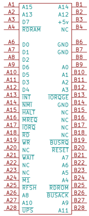
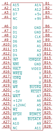 This is initial edge connector, which exists in all ZX Spectrum machines.
In 128K versions some of the signals were removed (most notable is /IORQGE) and few were added (e.g., Disk RD/WR in +3). I haven't created separate schematic elements for this connectors since the 48K one may still be used with minor limitations.
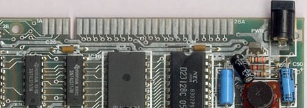
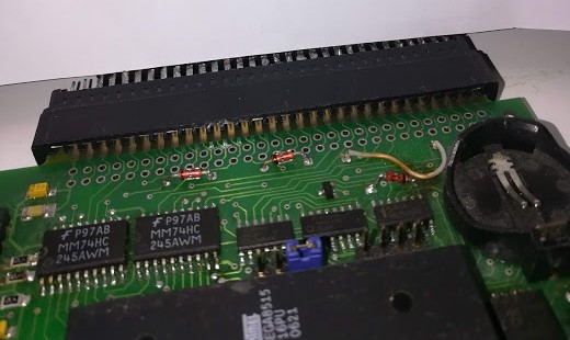
Same footprint may be used for peripheral devices as well. In this case the SL-56 slot pins should be soldered like this on both sides of PCB:
NemoBus
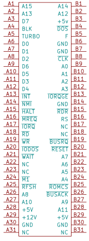 De-facto standard for Russian clones since late 90s. The first appearence of 62-pin option was in KAY-1024, however, 56-pin bus with almost the same signals was used in popular Scorpion ZS-256 computer. On the contrary to the original ZX Spectrum bus, the NemoBus is made as the slot (SL-62, ISA-8 form-factor).
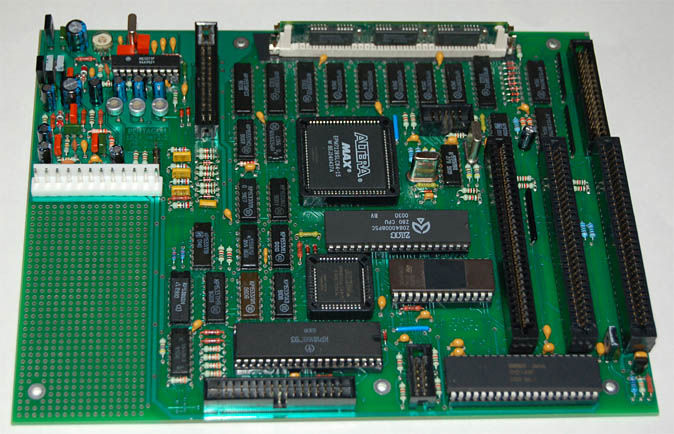
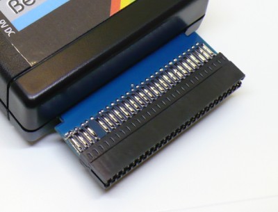
Extension devices contain edge connector. Since A31 and B31 are not connected (and most likely were added only because SL-62 slots are much more widespread than the SL-60), these pins are even absent in PCB sometimes:
Quorum Bus
 The edge connector, which was used in Quorum clone. It is virtually the same as standard ZX Spectrum 48 edge connector, but signals like 12V and video are not connected. Implemented physically as an edge connector, but the pins step is of Soviet standard (2.5 mm).
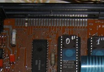
Also, it contains signals, which are specific for Quorum - e.g., UPS (Upper Screen, switch screen to 0xC000).