phidl
 phidl copied to clipboard
create xsection with that is not constant?
How could we create a cross-section that is not constant, for example, that has vias every 10um?
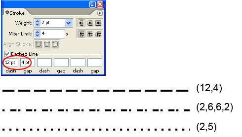
something like this

This is actually pretty easy conceptually. As long as you can create a list of path-lengths that will be "filled", it can be done within the path-generating function itself. For instance:
- I specify I want filled-sections 10um long, spaced with 5um gaps,
- I interpolate the generated path so that I can come up with a list of points spaced accordingly, for instance the first filled section goes from [0,10], the next from [15,25], the next from [30,40], etc.
- I generate multiple polygons out of those sections
The real tricky bit is -- is that enough? Assuming you can specify a list of filled/gaps like you would in Illstrator/Inkscape, is that sufficiently flexible/powerful enough? Or are there other use cases?
I see, would you create a new Cross-section type for this?
https://github.com/gdsfactory/gdsfactory/compare/main...extruding_segments
I'd need to think about it, but my guess would be no, this could be incorporated via an additional argument like dash = [10,5,10,8] or something like that without affecting anything else
Not sure if this is still an active project, but I found a way to hack this together. I needed something of this nature to create flux pinning sites in the center trace of a coplanar waveguide superconducting microwave resonator.
When creating a CrossSection, you can specify the width as a function. To get the dashed traces, you can specify this as a square wave. This works well if the number of points per unit distance is much greater than the number of dashes per unit distance you want. If not, then your dashes turn into hexagons.
Example of undersampled
With more points:
Still somewhat hexagon-like but much better. Now, we have the problem that this object is HUGE, so naturally we want to downselect the number of points. I thought to do this initially with the simplify argument in the extrude which implements the Ramer–Douglas–Peucker algorithm, but this led the "zero" width parts of the extrusion having some real width:
I think this happens because the RDP algorithm does not preserve the property of non-intersecting lines (although there does seem to be a slightly better version that preserves the non-intersecting lines with similar runtime complexity https://ieeexplore.ieee.org/document/1240992). To get around this, I compared pairs of adjacent points, and if they were separated by more than some predefined distance, I removed those points from the polygon.
Now, I only have the critical points of the geometry! It would be nice to have something more built in, as my squares are not exactly squares yet. My implementation is also fairly slow because you have to crank up the number of points and then downsample.
Thanks for the feedback. I'm going to implement a simple point_along_path(distance, offset) function should allow you to do this much easier. Alternatively, you can use gdsfactory as mentioned above whose interface is based on phidl and should be relatively similar
@sarangmittal So I think I was able to generalize this nicely with Path.interpolate() in the latest version (1.7.1). I've added some documentation to describe it, please let me know if this is suitable to what you need. @joamatab this is probably a useful function to copy over to gdsfactory also.
The inerpolate() method allows you to get arbitrary points along the length of the path (with or without an offset), returning both the (x,y) coordinates along the path as well as the angle along the path. This is particularly useful for adding periodic structures like vias alongside the length of the path:
from phidl import Device, Path, quickplot as qp
import  phidl.geometry as pg
import numpy as np

# Create an path as well as a via to repeat along its length
P = Path([(20,10), (30,10), (40,30), (50,30), (50,20), (55,20)])
D = P.extrude(0.5)
Via = pg.ellipse(radii = (0.5,0.2), layer = 3)


# Get a list of points where the vias should go
distances = np.linspace(0, P.length(), 35)
offset = 1
points, angles = P.interpolate(distances, offset)

# Create references to the via, place them at the interpolated points,
# and rotate them so they point in the direction of the path
for (x,y), a in zip(points, angles):
    via = D << Via
    via.rotate(a)
    via.center = x,y

qp(D)
This looks great! Next time I need to update this design, I will definitely implement this. In a little early testing, it seems to work well.
Thanks.