ACCELERATION_TEMPORAL
Hi all,
I'm currently working on ramps for acceleration temporal and before I forget this I write it down.
I found an issue in timer_set(). The part (current_counter - match_last_counter) can be negative.
So I changed this part on STM32F411 to:
      int32_t check_timer;
      check_timer = (TIM5->CNT - TIM5->CCR1) + 100;

      if (check_timer > delay) {
        return 1;
      }
The LPC should have something like:
      int32_t check_timer;
      check_timer = (LPC_TMR32B0->TC - LPC_TMR32B0->MR0) + 100;
On the simulator I had no issues, but maybe the AVR needs also a change.
It seems like this would be fixed more easily by making this change:
uint32_t check_timer;
check_timer = (uint32_t)TIM5->CNT - (uint32_t)TIM5->CCR1;
I don't know the size of TIM5->CNT and TIM5->CCR1, though. Presumably they are already unsigned. Maybe the casts forcing them to uint32_t are unnecessary.
This works because when you subtract a larger number from an smaller one in an unsigned context, the result overflows. We discard the overflow by using the unsigned holders and we are left with the correct difference.
So, to use an 8-bit example for simplicity, suppose we have
#include <stdio.h>
typedef unsigned char uint8_t;
uint8_t a = 250;
uint8_t b = 3 ;
int main(void) {
    printf("%d  %u  %u\n", b-a , b-a, (uint8_t) b-a );
}
The output is this:
-247 4294967049 9
9 is the answer we want, which is the same as 3 - (250-256) = 3 + (-250 + 256) = 3 + 6.
No, just test it. This won't work. In some cases the CCR1 is that much bigger, that (uint32_T)CNT - (uint32_T)CCR1 + 100 > delay. But in this case we don't have a short move.
I need some time for cleaning the mess on my desktop. But I will upload the code soon. :)


I don't understand your response. If CCR1 is the time of the previous step, and CNT is the current timer, then (unsigned)(CNT - CCR1) should be the time since the last step. The only exception is if the timer has looped all the way around and it's actually wrong by some multiple of the wraparound size. In that case, having a negative result is not helping; it's merely hiding the problem.
Specifically all I am suggesting is that check_timer should be unsigned (non-negative). This makes sense because the time since the last step can never be negative. Being unsigned gives us the extra help from the compiler to handle the wrap-around for us.
Yes, you are right. I have some ideas. The problem seems to be occur only at the first step. Thanks for pointing me in the right direction!
Looks like the issue is only on my STM. When CCR1 is <0xFFFFFFFF then I always get a short move. When I setup the CCR1 in the timer_init() to CCR1 = 0xFFFFFFFF everything is fine.
How is CCR1 > 0xFFFFFFFF? Is it a 64-bit variable?
It sounds like you have found the problem there; after looking at the code I'm not sure what your change here proposes to do. It seems to just move this math into a temporary variable. What am I missing?
How is CCR1 > 0xFFFFFFFF? Is it a 64-bit variable?
Ah sorry. Correct it to '<'.
I opened a new branch: https://github.com/Traumflug/Teacup_Firmware/tree/acc_temporal
This is currently on experimental + some stm32 and other stuff. I will rebuild this later on the current experimental.
Because the current code is a bit slow, I want to change the dda->c calculations like acceleration_ramping, only every 1-2ms. Achievable steprates are somehow 50kHz (maybe 60kHz) on my STM at 96MHz. Not that good...
Uh... Not that slow as I thought. The issue is different.
dda->step_interval[axis_to_step] =
  dda->step_interval[axis_to_step] - (dda->step_interval[axis_to_step] * 2) \
  / ((4 * (dda->delta[axis_to_step] - move_state.steps[axis_to_step])) + 1);
This part can't get smaller than 2693 with 1280 steps/mm, acc 2000 and f_cpu 96MHz. The step_interval of the first step is c0 * 0.676. (Equation 15)
c0 = 114683
c1 = 68810
...
c1346 = 2694
c1347 = 2693
c1348 = 2693
...
because:
c1347 * 2 / (4 * 1347 + 1) = 0!
2693 * 2 = 5386
4 * 1347 + 1 = 5389
First, if you're concerned about step rates, you should do all these calculations in dda_clock(). dda_step() cares about creating the next step according to given speeds, not on what this speed should be.
Regarding acceleration calculation: how about simple school physics:
speed = acceleration * time
and
step delay = 1 / speed
Acceleration is given, speed is known and approximate time can be found in move_state.last_time. That's the time of the most recent step on any axis. Hopefully precise enough for acceleration calculations, there could be issues at very low speeds/acceleration start.
Constant speed area is reached when acceleration calculation results in a value smaller than dda->c_min.
For deceleration it's the same calculation as with acceleration, but with time = move_duration - move_state.last_time. move_duration isn't currently stored in DDA, but that can change, of course. It's also calculated without acceleration in mind, which would have to change, too.
The remaining challenge is to get units right. We have speed in mm/min, acceleration in mm/s² and time in 1/F_CPU. And each intermediate result has to fit into 32 bits.
With all this, speed of the print head is known. Speed for single axes can be found by scaling. Conveniently there's muldiv(), which isn't cheap (some 750 clocks), but at least safe against intermediate overflows.
If it helps, I don't think you need to consider acceleration in move_duration. This is specifically because accel and decel are symmetrical. Consider the graph of speed vs. time. Speed increases during ramp_up, cruises at c_min for some cruise time, and then decreases during ramp_down. Symbolically we say this:
Ts = ramp_up time
Tc = cruise time
Td = time to begin decelerating (Ts + Tc)
Te = total move duration
For example, let's say Ts is 2 seconds and Tc is 5 seconds. This means we accelerate for two seconds before reaching cruise speed, then we cruise for 5 seconds. Since we accelerate and decelerate symmetrically, we find that Ts is also the amount of time it takes to decelerate to zero. So,
Ts = 2
Tc = 5
Td = 7 (calculated "move_duration")
Te = 9 (actual move duration)

Te = Ts + Tc + Ts = 2*Ts + Tc
Presumably move_duration is calculated as if we had no accel or decel. This assumes we begin our move at c_min (target speed) and maintain that for the duration of the move. It turns out that
move_duration == Td == Ts + Tc
Also: Ts = Te - Td
This is because if you add the speeds during accel and decel at isometric relative moments in time, you will find they always add up to our maximum speed (1/c_min). Mathematically, I can say this:
Given Vc = v(Ts) = v(Tc) (cruise velocity),
     For all 0<= x <=Ts, v(x) + v(Td + x) = v(Tc)
I can draw pictures if it is still confusing. It really confused me when I first read this concept. But I think it can be very useful when we are doing time-based acceleration profiles.
Traumflug:
you should do all these calculations in dda_clock()
Wurstnase:
only every 1-2ms
Sure :)
School physics looks like simple, but currently I can't see any benefit:
        // accelerating
        // speed = acceleration * time
        // dda->step_interval = 1 / speed
        // move_state.last_time in ticks
        // time = move_state.last_time / F_CPU [s]
        // acceleration [mm/s²]
        // speed = acceleration * move_state.last_time / F_CPU -> [mm/s]
        // speed_step = speed * STEPS_PER_M_X -> [(steps * mm) / (m * s)]
        // dda->step_interval = 1 / speed_step -> [(m * s) / (steps * mm)]
        // dda->step_interval = 1000 / speed_step -> [(1000mm / m) * (m * s) / (steps * mm)] -> [s / steps]
        // dda->step_interval = F_CPU * 1000 / speed_step -> [ticks / steps]
        // dda->step_interval = F_CPU * 1000 / (speed * STEPS_PER_M_X)
        // dda->step_interval = F_CPU * 1000 / (acceleration * move_state.last_time * STEPS_PER_M_X / F_CPU)

        dda->step_interval[axis_to_step] = muldiv(F_CPU, 1000, muldiv(ACCELERATION * STEPS_PER_M_X, move_state.last_time, F_CPU));
vs:
dda->step_interval[axis_to_step] =
  dda->step_interval[axis_to_step] - (dda->step_interval[axis_to_step] * 2)
  / ((4 * (dda->delta[axis_to_step] - move_state.steps[axis_to_step])) + 1);
@ me Not that big issue.
Precalculate F_CPU * F_CPU / (ACCELERATION * STEPS_PER_M_X) and then it's just:
static const axes_uint32_t PROGMEM temporal_const_P = {
  (uint32_t)((double)F_CPU * F_CPU * 1000 / ((double)(STEPS_PER_M_X) * ACCELERATION)),
  ...
}

dda->step_interval[axis_to_step] = pgm_read_dword(&temporal_const_P[axis_to_step])
                                   / move_state.last_time;
For the none-fast-axis we can precalculate a factor with ~~delta_total / delta[axis]~~
delta[axis] / delta_total.
For low acceleration/step-rates and high F_CPU we should move the 1000 out of precalculation.
96MHz^2 * 1000 / 40.000 / 500 > 32bit
static const axes_uint32_t PROGMEM temporal_const_P = {
  (uint32_t)((double)F_CPU * F_CPU * 1000 / ((double)(STEPS_PER_M_X) * ACCELERATION)),
  ...
}
Unless I'm mistaken, you apply the same acceleration to each individual axis here. As we know, participating axes have to move at different speeds depending on movement direction. Giving all of them the same acceleration means acceleration on slow axes is finished earlier than on fast axes, which puts them out of sync.
All axes have to finish acceleration at the same time to keep synchronisation (and movement direction). As far as my own considerations go, this requires to calculate acceleration along the movement direction first, then to derivate individual axes from there. Along movement direction there is no explicit STEPS_PER_M, it should be fine to simply assume one (e.g. 1000 steps/mm). The assumption eliminates when scaling to the individual axes.
Unless I'm mistaken, you apply the same acceleration to each individual axis here.
The math is really simple in it. Take the fast axis. Accelerate it by its constant. Accelerate other axis by a factor of delta[axis]/delta_total * constant of fast axis.
So acceleration of fast axis is maybe 2000. delta_total = step_count of fast axis. Maybe 1000.
delta_nonfast_axis = 200. So accelerate this axis with 200/1000 * 2000 = 400. Simple, isn't it?
@phord Need to read again your thesis. But can this handle lookahead with different accelerating and decelerating timings?
I think it can, but I haven't tried it at all. I'm hoping to use it for non-constant acceleration someday. Ideas from equation 8 in this paper on exponential motion planning.
@Wurstnase
Accelerate other axis by a factor of delta[axis]/delta_total * constant of fast axis.
I see. You want to derivate the other axes from the fastest one, similar to what ACC_RAMPING does. Sounds good!
@phord Ah, this paper from Bath :-) Yes, sounds very plausible. The curves in Fig. 5 lower half look a bit scary (sharp velocity corners!), but I think the idea is that if one adds two overlapping movements up, one gets a flat curve. A similar paper, way more detailed, is here: http://www.dct.tue.nl/New/Lambrechts/DCT_2003_18.pdf
I miss one thing with all these trajectory planning ideas: how do they do error correction? AFAIK, LinuxCNC does error correction with PID (like temperature control), even for steppers. PID can take action only after an error happened. The Bath paper says nothing about error correction. Teacup currently does error correction at movement endpoints (aka "don't stop moving unless all steps are done"). These advanced planning strategies make these endpoints going away.
We don't need V(t), but Vx(x) and Vy(y), after all.
I didn't mean to start this discussion here. I only found it interesting in the context of Td = dx / Vmax despite acceleration, which I first learned from studying this paper.
The way PID stepper drivers work is that they accumulate motion piecewise by simple addition over time. If they find their step came too late to hit the calculated movement time, then this is an error which is compensated for by the PID loop. The compensation comes in the form of decreasing the next step delta, causing the acceleration to increase.
So you choose a predicted first step time and then you periodically adjust acceleration (linearly), accumulate velocity (geometrically), and accumulate position, the sum of the discrete velocity averages. At some point you will find that your position "steps", from rounding down to X to rounding up to X+1. This is when you should have stepped. If you stepped 300us ago or 500us from now, then this is your error value.
I think the paper is agnostic about error feedback. Maybe it is measured with a servo pot or some other positional indicator, or maybe it is calculated like the stepper-PID idea. The primary idea in the paper is about constraining jerk to a continuous function across the whole movement in order to minimize actual errors.
The theory about movement joining of symmetrical accel/decel phases still interests me, but you are right that it is further complicated by the separation of axes. It would be easier to do with ACCELERATION_TEMPORAL where we can use Vx(t) and Vy(t), but this feature has been abandoned for a long time. It's interesting to see it come up again.
Learned something today, from the Lambrechts paper (the same I linked above already). This is from page 26:
 To the left is a "generator", which outputs 1, 0 or -1. This "signal" is stuffed into the first integrator at discrete time steps, e.g. every 2 milliseconds. The output of that integrator is the integral of the original signal, which happens to be jerk.
This jerk signal (now any value ~~in the range {-1, 1}~~) is put into another integrator, which integrates up again.This gives acceleration. Yet another integrator in the chain gives velocity. The last integrator gives position, and that integrator happens to be not some mathematical formula, but our stepper motor.
The non-trivial part here is to calculate the original signal. There's a matlab script at the end of the paper to calculate the signal in multiples of an adjustable time step. This script even takes error correction into account. But that's not my point here.
My point is, if two of these integrators get chopped off, we have second order acceleration, which is what Teacup currently does. Then there's a simple acceleration signal: 1 = acceleration, 0 = keep speed, -1 = decelerate. When to give which signal is easy to calculate.
Now, "forward Euler discrete time integrators" sounds impressive, doesn't it? Impressive name, simple math :-) It's as simple as velocity = velocity + signal, done at each time step. "At each time step" = once in dda_clock().
The magnitude of the signal is simple, too: it's the speed change happening from one time step to another: signal = dv = acceleration * 2ms. A constant value.
To sum up: instead of doing complex math calculations, one can simply add up velocities at each time step. Only for the adventurer: third order acceleration (constant jerk) would mean two such additions at runtime, fourth order acceleration three such additions. In any case: all the complex math is done at preparation time.
Nice! I tried to write up some similar descriptions before. The math is so simple but it still only gives us V(t). We still must calculate 1/V(t) to be useful. But maybe we can afford to do that every 2ms, huh?
2 ms = 32'000 clocks on the slowest controller. Perhaps 10'000 clocks taking the time for step generation and G-code parsing into account. One 32-bit division = 600 clocks, IIRC. Much less on Wurstnase's F4, of course. And with some luck this 1/V and scaling to individual axes can be done with one division.
To take this two steps further:
- It would be trivial to extend this to permit variable acceleration. Simple linear acceleration gives smoother velocity curves.
- A linear approximation can be used to map the exponential graph from the Bath paper. I've bashed some code to experiment with this off and on. In fact that's what I was doing when I discovered #215
Sorry -- Didn't mean to close it. But I wonder, @Wurstnase, should we close it?
To keep my head from exploding I started writing a wiki article: http://www.reprap-diy.com/printer_controller_trajectory_planning
should we close it?
Closing? For my part I just warmed up with the topic.
Closing can be done when acceleration with ACC_TEMPORAL is working for all axes and some prints of PCB millings were done. Ideally with lookahead already.
This part of Teacup could become some kind of a unique feature in the current reprap community. I just started with it. A first fast duty test with temporal/schoolphysics/dda_clock only for acceleration works great.
I really fell in love in that part of code. Later I could add for the F4 PWM for each stepper. An interrupt could count the steps. With that I guess I can reach much faster rates because the interrupt will be very simple. Just count the pwm and stop it until finish.
Oh, I didn't realize this is a general "Implement ACCELERATION_TEMPORAL" issue. I thought the first comment about a suspected bug in timer was the real issue.
Three items come to mind about your wiki.
- You mention calculating new math "every other microsecond", but I think you mean millisecond.
- It is not necessary to calculate four orders of equations at runtime in order to achieve the same result. The Bath paper looks at this specifically. The key feature of that article is that a formula is proposed which results in smooth f, f' and f'' (velocity, acceleration, jerk), which provides direct formulae for all three, and which bounds each function to desired limits. Thus using only the
velocityformula from that paper and ensuring thealphavalue is chosen to respect the limits on the other two graphs is enough to get a smooth curve on all three levels. - It is reasonable and useful to combine both Non-linear acceleration and Velocity Calculation at Discrete Time Intervals to achieve a smoother hybrid. Let me explain:
Velocity Calculation ... works by calculating a new step-time (velocity) for the current desired velocity every 2ms. Let's call this target. Ideally this is the average speed we want to achieve for the 2ms period, so perhaps it is based on V(now+1ms) instead of simply V(now).
target = V(now + 1ms)
In either case, we use this step interval for 2ms until we run again to calculate a new value for target. Suppose instead we calculate two values called target and next.
target = V(now)
next = V(now + 2ms)
Now next holds the velocity we want to use at the end of this interval. Rather than using a fixed step value during this interval, we can adjust the step value REPRAP-style by simply adding some constant after each step to target so we end the interval at target = next. We can calculate this constant (the slope from target to next over 2ms) easily enough.
Importantly it does not overly complicate our 2ms math by requiring us to do twice as much work. We only need to calculate both target and next at the start of our move. And then each subsequent 2ms calculation becomes simply this:
target = next;   // re-use previously calculated value
next = V(now + 2ms)
Except we do also have to calculate our slope, too:
steps_this_interval = 2ms / (( next + target ) / 2)
slope_this_interval = (next - target) / steps_this_interval
But I think this might simplify further:
slope_this_interval = (next - target) / steps_this_interval
                    = (next - target) / (2ms / ((next + target)/2))
                    = (next - target) / 2ms * ((next + target)/2)
                    = (next - target) * (next + target)/2 / 2ms
                    = (next*next - target*target) / 4ms
Weird.
Conveniently this model (using target and next) fits well into a method which uses a linear-approximation of some complex velocity curve via a lookup table.
I think you mean millisecond
Thanks, fixed. BTW., feel invited to edit this wiki yourself.
The key feature of that article is that a formula is proposed which results in smooth f, f' and f'' (velocity, acceleration, jerk), which provides direct formulae for all three, and which bounds each function to desired limits.
That's true and also the reason why I don't consider this to be superior to the approach in the paper from Eindthoven. Maybe not even implementable (t ^^4, cubic root) to be calculated within 2 milliseconds on our limited hardware. Worse, this rather complex formula (it's the third line of formula (2) on the first page, isn't it?) has to be calculated on each time step, not only once before starting the movement.
Paul Lambrechts approach puts all the complexity into pre-calculations, but at runtime it's as simple as adding up two numbers. That's even a bit easier than @Wurstnase's approach above and triggers the "it's sane, because it's simple" detector here. A genius strike similar to the one of Mr. Bresenham.
The lesson I learn from the Bath paper is that one can overlap movements, even if they do S-shaped accelerations.
Thanks, fixed. BTW., feel invited to edit this wiki yourself.
Yes, I was going to, but I was too busy to wait for the registration cycle to complete. :-]
Maybe not even implementable (t ^^4, cubic root) to be calculated within 2 milliseconds on our limited hardware.
Right. But as the paper points out, the graphs are amenable to linear approximation which should preserve the smoothing features as well. I have generated a linear approximation table of the normalized velocity data and I've done some work on velocity calculations at run time. But I keep getting interrupted by $dayjob.
The lesson I learn from the Bath paper is that one can overlap movements, even if they do S-shaped accelerations.
That was the interesting part to me, too, even though the paper mentions that it is theoretical and untested. In fact, I stumbled upon this paper while looking for a reasonable lookahead algorithm back before you got one working. :-)
After I read the paper a few times and really grokked its contents, I became more interested in the exponential function itself. But I keep getting distracted. Maybe it's not worth pursuing, but it gives me something to play with when I can't sleep.
Just a short sentence for the first post. Hardware-Debugging >> all.
Short delays is everything < 160 not 100. I made some measurements and it took 130 to 152 cycles to finish the interrupt on my STM32.
Also, the very first interrupt will occur at 0! So setting up the capture-compare-register at init to 0xffffffff solves this. Without it, the ccr > cnt and cnt - ccr becomes negative and the problem begins.
So first part is finally solved!
Also, the very first interrupt will occur at 0! So setting up the capture-compare-register at init to 0xffffffff solves this.
Excellent catch!
I made some measurements and it took 130 to 152 cycles to finish the interrupt on my STM32.
This makes me a bit wondering what happens in this time. The seemingly computing intensive part, finding out which axis to step next, is done before setting the timer. Is testing four 32-bit values against zero that much work?
I start counting in timer_set() just before the if statement and stop couting in the IRQHandler just after queue_step().
Is testing four 32-bit values against zero that much work?
Well, I'm little bit unsure from where to where I should measure. The part between while(set_timer()) and unstep() is only 41 to 82 cycles.
Has anyone looked at how TinyG is doing acceleration? They claim 3rd order with G1 and 6th order with G2 https://github.com/synthetos/TinyG/wiki/Jerk-Controlled-Motion-Explained
While looking again into the temporal code because I what to work with the TODO:
    // TODO: instead of calculating c_min directly, it's probably more simple
    //       to calculate (maximum) move_duration for each axis, like done for
    //       ACCELERATION_TEMPORAL above. This should make re-calculating the
    //       allowed F easier.
I have some issues to understand this part:
      uint32_t move_duration, md_candidate;

      move_duration = distance * ((60 * F_CPU) / (dda->endpoint.F * 1000UL));
      for (i = X; i < AXIS_COUNT; i++) {
        md_candidate = dda->delta[i] * ((60 * F_CPU) /
                       (pgm_read_dword(&maximum_feedrate_P[i]) * 1000UL));
        if (md_candidate > move_duration)
          move_duration = md_candidate;
      }
move_duration is in ticks, but md_candidate is something in 1/µm?
distance is in delta_um-units.
dda->delta[i] in steps. Should this be delta_um[i]?
Later we will calculate the step_interval with:
      for (i = X; i < AXIS_COUNT; i++) {
        dda->step_interval[i] = 0xFFFFFFFF;
        if (dda->delta[i])
          dda->step_interval[i] = move_duration / dda->delta[i];
      }
move_duration is CPU-ticks and dda->delta is in steps. So we get ticks per step. Which looks ok.
@Traumflug you can pick https://github.com/Traumflug/Teacup_Firmware/commit/ae2604cccd6afd and maybe also https://github.com/Traumflug/Teacup_Firmware/commit/848825b35. Ramps for temporal are not final working.
I just noticed your TinyG mention. Their code relies on heavy math libraries and floating point calculations. It must take many millis to plan each movement!
I played with implementing a similar method but in simpler integer math a while back. I might revisit it someday.
Teacup does pretty impressive things with constant-acceleration already, but jerk-limited variable acceleration might make things a little smoother. With lookahead enabled, however, you will primarily notice improvements only when Teacup starts or stops to/from Velocity=0. It is possible that we could move the print head faster if we learn to limit for Jerk independently from Acceleration. But I expect the improvement would be minuscule.
When you have a lot time while traveling to work, you could get nice ideas.
I think I can introduce ramps and lookahead soon to acceleration temporal. :)
Lookahead for ACCELERATION_TEMPORAL by overlapping movements, please. This way we get rid of these instant direction/speed changes and get support for quadratic Bezier movements for (almost) free.
temporal with ramps:

acceleration ramping:

New things I've learned. c_candidate in dda_step() can be negative. So in that case just step immediately the next axis. Otherwise other axes can overtake this 'negative' axis, because 'negative' unsigned integer gets big.
You will find some small spikes. This are some of those small 'negative' delays.
in dda_step():
    move_state.last_time = move_state.time[dda->axis_to_step] +
                           dda->step_interval[dda->axis_to_step];

    do {
      int32_t c_candidate;
// other code...
      int32_t dda_c = 0x7FFFFFFF;
      for (i = X; i < AXIS_COUNT; i++) {
        if (move_state.steps[i]) {
          c_candidate = move_state.time[i] + dda->step_interval[i] -
                        move_state.last_time;
          if (c_candidate < dda_c) {
            dda->axis_to_step = i;
            dda_c = c_candidate;
          }
        }
      }

      if (dda_c < 0)
        dda->c = 0;
      else
        if (dda_c == 0x7FFFFFFF)
          dda->c = 0xFFFFFFFF;
        else
          dda->c = dda_c;

      // No stepper to step found? Then we're done.
      if (dda->c == 0xFFFFFFFF) {
        dda->live = 0;
        dda->done = 1;
        break;
      }
    } while (timer_set(dda->c, 1));

Current code: https://github.com/Traumflug/Teacup_Firmware/tree/acc_temporal_ramping It's my current local working version and needs some rework.
You will need to fix the negative c_candidate some other way than just "step immediately". Those spikes likely represent lost steps because your stepper cannot react that quickly.
But I think you know this already. I just want to make it part of the discussion.
I'm excited to see where this goes. :+1:
But I think you know this already.
I don't really think about it. But it looks like, that most spikes comes at deceleration. I guess this is, because move_state.last_time is calculated in the beginning of a new interrupt. But between it can change. On acceleration this is not a big issue because the last timer is always slower. At deceleration the dda->step_interval[i] will become slower in dda_clock().
The solution could be calculating last_time after the do-while before existing the current interrupt.
You will need to fix the negative c_candidate some other way than just "step immediately". Those spikes likely represent lost steps because your stepper cannot react that quickly.
While the double-step in the last picture clearly shows a bug, having negative c_candidate's isn't fundamentally wrong. Other than ACCELERATION_RAMPING, ACCELERATION_TEMPORAL always does one step per dda_step() call, only. Which means, if three steppers should do one step on each at the same time, three calls to dda_step() are required. Step on the first motor happens in time, but also consumes some time, so the other two steppers are somewhat behind, with a negative c_candidate.
Maybe this sounds like a severe penalty, but in practice, two motors stepping at the exactly same time are the exception: they happen with exactly 45 deg movements and a few other angles, only. Arbitrary angles mean evenly distributed steps on each individual motor, but arbitrarily distributed steps on all the motors together. A step loss happens only if two steps happen at the same time on the same stepper, which happens to be a bug.
Step on the first motor happens in time, but also consumes some time, so the other two steppers are somewhat behind, with a negative c_candidate.
We check such things with "check_short". So negative numbers shouldn't happen. If, we need to enlarge the "check_short". https://github.com/Traumflug/Teacup_Firmware/blob/acc_temporal_ramping/timer-avr.c#L182
The double step in the last picture could onlyhappen when the step_invterval changed between interrupts. https://github.com/Traumflug/Teacup_Firmware/blob/acc_temporal_ramping/dda.c#L636-L637 In that case, especially for acceleration
move_state.last_time = move_state.time[dda->axis_to_step] +
                           dda->step_interval[dda->axis_to_step];
dda->step_interval will increase. last_time is bigger as it should be and in
c_candidate = move_state.time[i] + dda->step_interval[i] -
                        move_state.last_time;
c_candidate becomes negative.
A step loss happens only if two steps happen at the same time on the same stepper, which happens to be a bug.
Right. And I hesitate to add that it is not necessarily a bug to have a "fast" step which is not immediate. The stepper driver operating in full-step mode has only four positions. When it which receives two steps too fast for it to handle with a motor already at some velocity, you might consider it ambiguous: "was it two steps forward or two steps back?"; they end up at the same position. But since the hardware is already moving, the physics will force the motor to move to the correct position anyway. You may experience some momentary torque loss, but you're not otherwise in much danger until you step three times too fast. But this is only a danger if you do not use microsteps.
And I hesitate to add that it is not necessarily a bug to have a "fast" step which is not immediate.
Thinking of it I tend to agree. Avoiding these fast steps requires to predict the future, which is likely quite some computational work. They also shouldn't happen at more than 4 ms between two steps (2x speed recalculation interval, < 250 steps/second). If that's still not sufficient, full step mode isn't exactly in fashion and at any higher microstepping (1/4, 1/8, ...), such a fast step is leveled out mechanically, as you nicely described it, as long as the stepper driver logic is fast enough to actually count two steps.
I am seeing much larger spikes and I see them almost always at the start of a move. They also appear in the simulator.
The problem is that during acceleration the step_interval is updated in dda_clock to a value smaller than it was previously. It may be much smaller; the 2nd step interval is less than half the first step interval.
dda_step: steps once and then timer_set(step_interval[A]) dda_clock: calculates new step_interval for step # 1; step_interval[B]
Now, if step_interval[A] >= 2*step_interval[B], then by the time dda_step runs again it is already "behind" by two steps on the same axis, so it tries to catch up by firing twice immediately.
I'm not sure of a sane way to fix this. I don't think it's reasonable to change the step-interval for the current pending step, nor should we change the step-interval now such that the clock has already skipped more than 1 step_interval on an axis. I guess we mainly want to ensure we do not get more than 1.5 step_intervals behind because of dda_clock, but maybe 1.5 is too close to seeing and edge-case where we average intervals over several steps to achieve our target. So maybe we can test for being more than 1.75 steps behind and then drop extra steps which we know we can never catch up to.
Maybe the real sane fix is to apply acceleration to each axis independently. I think you're already considering that.
But in the meantime, try this: 159e565
I tested it and I do not see any spurious "fast steps" now.
Maybe it makes more sense to do the fast-step recovery in dda_clock. But I was hesitant to modify move_state there outside of an ATOMIC. But I also don't like that extra while loop in dda_step. I wonder if this is any better: e96b3ff

It doesn't check the current pending timer interrupt, so it offers no guarantee that the interval will not still
fail. But at least it doesn't produce any spikes in the smooth-curves test with my test profile.
Thanks for support.
I am seeing much larger spikes and I see them almost always at the start of a move. They also appear in the simulator.
Yes, and it is always the fast axis. I have a picture at home, where you can see this. (I will post this later) And it looks like, that there is only one spike, every time at the same point.
Before I made the change, where the last_time was calculated (https://github.com/Traumflug/Teacup_Firmware/commit/b6dfcaddbb3d2eb), this were always at deceleration phase.
 This is the picture.
I make a cleaner branch. I don't want to rebase the last one, because maybe I missed something. https://github.com/Traumflug/Teacup_Firmware/tree/acc_temporal_ramp2
Here are again two pictures of my last commit, without the two from @phord . First is with acc 200, latter with acc 2000.


Unfortunately the 2 commits from Phord doesn't work with my setup. The simulator freeze. (or maybe take a very long time)
What about just my first commit?
Those while loops I added scare me in general. They can freeze if the time counter gets very large (near overflow). But if we get that close to overflow on the timer, I think we might have other problems. Still, maybe it is the cause of your freeze with my hack. I don't see a hang either in the simulavr or in the simulator.
Maybe my hack freezes when the queue is empty. I noticed the simulavr always kills the process in the end, but it completes the gcode processing first. But I haven't seen this problem in the simulator, so... :man_shrugging:
I tried both commits :(
I also tried to modify the timer a bit when the same stepper stepped twice in the do-while(set_timer). But this hangs also.
Hmm... One more idea. While setting last_time before the loop the spikes appear at deceleration and setting last_time after the loop the spikes appear at acceleration, why not combine them? Until acceleration finished we set the last_time before the loop. After that we add dda->c to last_time after the loop?!?
hu ha...
two commits. two result. little bit different, but in both cases better than before :)
80000 steps/m 200 acc
before:
 testing with rampup_steps:
 testing with rampdown_steps:

rampdown_steps with acc 2000:
 ACCELERATION_RAMPING acc 2000 for comparison:

How should this picture looks like when lookahead is active? I just test the master. One time ramping with and one time without lookahead. But I don't see any different.
with lookahead:
 without:

Here's a pair of pictures with (top picture) and without (bottom picture) lookahead: https://github.com/Traumflug/Teacup_Firmware/issues/189#issuecomment-263130589
Maybe your MAX_JERK is close to zero.
 temporal lookahead:

Spurred on by this discussion thread I have made some dramatic changes towards implementing integral acceleration. I now have constant acceleration working cleanly in the simulator with lookahead and without any rampup_steps or rampdown_steps calculations, without inv_sqrt, and with significantly less math.
When I got rid of exact dda->c calculation as a function of step_no I ran into trouble. The trouble is caused by using simple velocity every 2ms to calculate our c_min for the next 2ms. The deceleration steps are unpredictable because it may not align with our 2ms offsets exactly the same as our acceleration steps did.
Some background: We calculate the velocity in dda_clock once every 2ms. We determine the velocity to apply by calculating the expected velocity given the number of steps we have accelerated or decelerated. Velocity(steps) = { velocity expected at acceleration step steps }
We apply that velocity in dda_step at each step time. If multiple steps occur in 2ms, those steps all get the same velocity. We can calculate the number of steps that will occur in that 2ms period, but we don't. But we will later.
When I remove the steps-based velocity calculations and rely on a cumulative acceleration constant instead, things get wrong when the 2ms-clock does not align exactly the same on the deceleration as it did on the acceleration. The result is that my calculated number of steps during decel-phase is not the same as my calculated number of steps during accel-phase.


In the first graph the calculated velocity at each dda_clock during acceleration perfectly matches the calculated velocity during deceleration. But in the second graph they are different. This is because the cruise time is not perfectly aligned with dda_clock, so the calculated velocities are different at each deceleration step. Indeed the velocities should be different at each of those points in time. This would be ok if we were calculating our velocity more than once per step. But it causes us to misjudge the end steps during deceleration at the very end of the move, where this is particularly critical.
Introducing the Planner
My solution to this problem is to change when we apply the calculated velocity very slightly. I still calculate the expected velocity (V) for a 2ms period. I also calculate the number of steps to occur at that velocity (N). The amount of time taken by N steps at V velocity is V*N. It might be 2ms, but it might be more or less.
I put these V and N values in a queue of steps. I don't store one value for each step, but I store two values for each desired velocity change, V and N. This queue of planned steps belongs to the Planner.
So, I might have a queue that looks like this:
Velocity   Steps
     500       4
     700       5
     900       6
    1000     137
     900       6
     700       5
     500       4
Notice we take the same number of steps at the same velocities during accel and decel now. Also, the "cruise" period at a constant speed takes just one space in the queue (137 steps at V=1000).
The goal is to have at least 2ms worth of steps in the queue at all times. I can now disassociate the 2ms clock from the velocity-averaging-period, but it is necessary to ensure that we have enough space in the queue to still hold more than 2ms worth of steps so we do not underflow the step engine in dda_step.
To help smooth our motions a little bit more, I actually store the slope of the velocity rather than the actual velocity in this queue. It looks like this:
      dV   Steps
     200       4
     200       5
     100       6
       0     137
     100       6
     200       5
     200       4
Now it's easy to identify the "cruise" period as the point where dV=0. Also we can apply the dV iteratively at each step. For example, each of the first four steps in this queue would occur not at "500" but at "500, 550, 600, 650" instead. Or something close to that.
The actual velocity is inverted (F/v) so we get a slightly non-linear velocity increase during each element in the queue. But this is averaged and corrected by the alignment with the next queue element and looks quite nice over all. It's a slightly smoother curve than we had before, but this is not the primary goal.
The primary goal is to allow us to calculate steps more than 2ms ahead of time and to allow us to plan our deceleration uniformly and consistently.
And it works. I still need to adapt it to work with existing accelerators. And clean up a bit.
More later.
Very impressive work. I'm looking forward to test this. (Keep in mind, that you need to change dda_step() again, else you could get wrong results https://github.com/Traumflug/Teacup_Firmware/issues/260)
Yes, I rebased it onto experimental, but I forgot issue #260 is still open. We should close that soon.
ACCELERATION_INTEGRAL
I've been calling this new acceleration math integral acceleration since it performs a piecewise integration of some acceleration constant to determine velocity, and then it integrates velocity to find position. But I have not melded it cleanly with the existing code and there is no #define ACCELERATION_INTEGRAL. Instead the code currently usurps ACCELERATION_RAMPING, and it breaks all other accelerations, almost certainly.
I was hoping to provide some logical squashes yesterday, but at the last second I introduced two stupid bugs that had me frustrated for several hours. These are fixed now, but I've wasted enough time on it. Here's a pretty graph to show some results:

This is a graph of the X-position vs. time when plotting testcases/smooth-curves.gcode. The greenish line is the graph of the output from the simulator from experimental with ACCELERATION=10 and LOOKAHEAD enabled. The purple line is the same graph using the new integral acceleration code. Two things to notice:
- The curves are a near perfect match. This validates not only the new integration code but also shows what a nice job our existing estimation function does at hitting the right mark.
- The new curve is slightly faster than the old one. I think this is caused by some intentional error in the existing algorithm which favors slower speeds at C0 and C1 than are necessary. But it could also be an error in my code.
Here's how I produce a single graph if you want to try to replicate this:
make -f Makefile-SIM
./sim -o -g -t0 testcases/smooth-curves.gcode
gnuplot -p -e "plot 'datalog.out' using 1:2  with steps;"
And here's a higher resolution version of the graph:

I have thought a little bit about how to apply the planner to ACCELERATION_TEMPORAL. That's what this issue/thread is about, isn't it? :grin:
I don't have a good answer yet, however. I suppose you could run four planners at once. The PLANNER structure could be molded to accomodate the extra information in a single structure, but planner_get and planner_put would have to be tweaked, too.
Another option is to make the PLANNER queue really long to allow distinct planned step-times for each axis to be mixed into a single stream. I doubt this would even be fast enough to work during dda_step.
I envisioned the planner being more versatile so it could handle TEMPORAL, RAMPING and INTEGRAL. But I don't think that's what I ended up implementing.
One more thing: I've only done any work in the simulator. I expect this to work on real hardware, but I doubt it does. It seems to hang in simulavr after a few steps. Maybe I've messed up how timers get started.
Can you also upload your current code with the rebase of #260? I failed to rebase it. My first test with a rebase ends in a div by zero.
I've rebased it all together now and pushed to accel-integral. It works fine for me on the simulator with smooth-curves.gcode. But I noticed it hangs on swan-test.gcode with a "DDA underflow". That's a problem in the planner. I'll look into it.
I found the planner problem that caused it to hang. It was scheduling too many steps when movements were joined at high speed so the planned motion overlapped the two movements. This caused the planner to get confused about its next movement.
I pushed this to accel-integral. I've still tested it only on the simulator so far, but you're welcome to explore it and let me know if you see any surprises.
It still needs a lot of cleanup. I'll work on that next.
ERROR: dda_queue.c:77: assert(mb_tail != mb_plan) failed; Advancing tail past plan :confused:
Interesting. Can you tell me how you did that? What's in your printer config? What gcode were you sending? What commandline did you use to start sim?
config.h:
#include "config/board.gen7-v1.4.h"
#include "config/printer.mendel.h"
sim:
./sim -t0 -g swan-test.gcode -o
That's weird that it didn't fail for me before. I was running basically the same thing you are. But it fails for me every time now.
I fixed it and pushed the change to accel-integral. Thanks for testing.

That looks awful. We should add a simulator unit test to validate precision. I was happy when smooth-curves came out exactly right. But I obviously need more complicated motions to catch all the possible regressions. Will experiment more next week.
@Wurstnase This is fixed now. I've still only tested in the simulator so far.
You are coming closer :+1: Swan looks perfect. While testing the dda_queue-issue zungman sends me a gcode with very short moves, which makes problems. Very short and very fast to test.
Unfortunately this will fail with your code.
accel-integral:
 experimental:

Test-gcode:
G92 X81 Y101
G1 X81.175 Y101.370 F3300
G92 E0
G1 E-0.6000 F1800
; outer perimeter
G1 X85.406 Y101.422 F10800
G1 X85.452 Y101.429 F10800
G1 X85.982 Y101.464 F10800
G1 X86.414 Y101.466 F10800
G1 X86.843 Y101.440 F10800
G1 X96.279 Y101.558 F10800
G1 X96.279 Y101.968 F10800
G1 X110.404 Y101.968 F10800
G1 X130.105 Y101.978 F10800
G1 E0.0000 F1800
G92 E0
printer.zungman.h With that printer-file you need to comment out the sanity-check in dda_lookahead.h.
Also you can see a very flat curve in the end of the deceleration phase.
Zoomed in:

I don't see any problem with the zungman gcode test in the simulator. I'm unable to get it to work in simulavr for some reason. It never starts processing the gcode. What board.h did you combine with his printer config for the test configuration?
Take the board.gen7-v1.4.h. Set the baudrate to 38400. Uncomment the DEBUG_LED_PIN. Copy the STEPS_PER_M_X and STEPS_PER_M_Y in the config.h file and comment them out in the printer-file.
Now the simulator should start.
While I'm get bored I found some code I've changed.
ctypes and python, testing.
While this change is not the problem, I have an other finding.
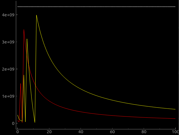
md_candidate/move_duration calculation for temporal moving will overflow at low speed.
move_duration = distance * (60UL * (F_CPU / 1000) / dda->endpoint.F);
Red is 16MHz uC and yellow 48MHz uC. Distance is 18mm in this example. Y-Axis is the move duration. X is the feedrate.