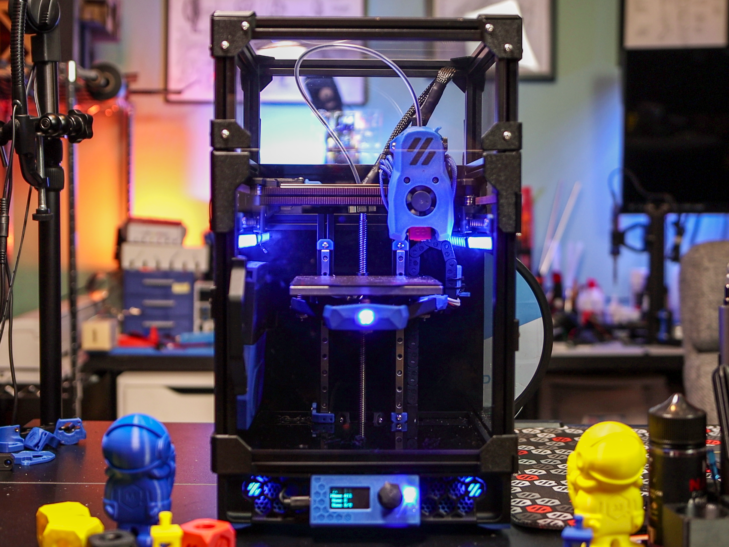
Formbot-V0
 Formbot-V0 copied to clipboard
Details/Documentation for the Formbot V0 Kit
Formbot-V0
Details/Documentation for the Formbot V0 Kit
Detailed Review
 https://www.youtube.com/watch?v=wvUrcIFF510
Stream Series
Check out my full build stream series here:
 https://www.youtube.com/playlist?list=PLwWNdxHVFVf1DbI2nGngUB0O9TWeXn2Sx
Voron DB Entry
 https://vorondb.com/printer/V0-3207

Features
Note: For each of the features/mods please make sure to go to the repective documentation to download and print all of the necessary STLs.
- Kirigami Bed Frame
- BTT Pi V1.2
- BTT SKR Pico
- BTT V0 Display
- CHC V6 Hotend (Upgradeable to Dragon/HF)
- Double Sided PEI Sheet
- Crimped Wiring Looms
- Moons Motors
- Stainless Steel Rails
- MIC6 Cast Aluminum Build Plate
- Polycarbonate Panels
- Gates Belts
- Vivedino 60W Silicone Bed Heater
- Stainless Steel Hardware
- Umbilical Board + Harness
- NOT Makerbeam XL Extrusion!!! LDO Style
- Meanwell 150W PSU
Aliexpress Listing: https://s.click.aliexpress.com/e/_Dk19GYN
Formbot Listing: https://www.formbot3d.com/products/voron-v02-corexy-3d-printer-kit-with-high-quality-parts?DIST=RkFPFVk%3D
Disclaimer: Purchases made through some store links may provide some compensation to Ballistic Tech.
Helpful info
Most of this is set in the printer.cfg file I've provided:
https://github.com/SrgntBallistic/Formbot-V0/blob/v0.2/Firmware/bigtreetech-skr-pico-v1.0.cfg
Replace the entire contents of your printer.cfg file with the contents of the file linked above. Follow the instructions in the comments to add the serial Ids for your MCU and Display.
Motor Models
Helpful for the Autotune TMC Klipper Plugin
- A/B - MS14HS5P4150-11
- Z - LE174S-T0808-200-0-S-065
- E - CSE14HRA1L410A-01
Link: https://github.com/andrewmcgr/klipper_tmc_autotune
Max Motor Currents
- A/B - 1.5A
- Z - 0.65A
- E - 1.0A
Motor drawings with current ratings
A/B - https://github.com/SrgntBallistic/Formbot-V0/blob/v0.2/Images/Motors/a-b-motors-drawing.jpg
Z - https://github.com/SrgntBallistic/Formbot-V0/blob/v0.2/Images/Motors/extruder-motor-drawing.jpg
E - https://github.com/SrgntBallistic/Formbot-V0/blob/v0.2/Images/Motors/extruder-motor-drawing.jpg
65% Run Currents
Voron recommends 60-70% (0.6-0.7) to start I chose 65%. Increase as needed but try to stay below 80-90%
Run Current = rated_motor_current x 0.707 x 0.65
Plug the max currents above into the equation with your desired percentage
- A/B - 0.65 x 0.707 x 1.5A = 0.69 (NICE!)
- Z - 0.65 x 0.707 x 0.65A = 0.3A
- E - 0.65 x 0.707 x 1.0A = 0.46A
Thermistors
- Formbot Bed - "Generic 3950"
- Formbot V6 CHC Hotend - "ATC Semitec 104NT-4-R025H42G"
- Check Klipper docs for the correct sensor type based on your thermistor/hotend
Extrusion Identification
All of the extrusions in the Formbot V0 kit are tapped on both ends. This means that using the V0 Manual extrusion identification diagrams can be a bit confusing. For 4 sets of extrusions where the manual differentiates them by tapped ends, you can consider those extrusions to be identical.

Identical Extrusions
- A/B
- C/H
No Drop Nuts

No drop nuts are very helpful for preventing preloaded M3 Hex Nuts from sliding around or falling out of the frame during assembly. They also allow you to pre align the nuts and hold them in place while you attatch parts to the frame.
The Formbot Extrusions are NOT MakerBeamXL profiles. They are closer to LDO's 1515 Extrusion. As such the no drop hex nut mods designed for LDO's kits work well with the Formbot kit.
 Above: Left - Formbot Extrusion, Right - LDO Extrusion
Be Careful
I used them and found them very helpful. One big thing to note is that using the normal no drop nuts for the magnetic door latch can cause an issue. The spacing for these printed parts is such that using no drop carriers will cause them to be too far apart.

I used normal no drop nuts for these and had to essentially break apart the nut carriers to have them align with magnetic door latch parts.
There is a specific version of the No Drop Nut that is designed to be used here:

Kirigami Bed
 GitHub: https://github.com/christophmuellerorg/voron_0_kirigami_bed
Manual: https://github.com/Kagee/kirigami-bed-manual
LDO Kirigami Docs: https://www.ldomotion.com/p/guide/18295873486461670
Remixed Formbot V0.2 Kirigami Frame Nutblock: https://www.printables.com/model/659769-kirigami-bed-stealth-nut-block-remix-to-fit-formbo
Remixed Formbot V0.2 Kirigami Frame Chain Mount: https://www.printables.com/model/659415-kirigami-bed-chain-mount-remix-to-fit-formbot-kit
The Formbot kit only comes with the Kirigami Frame. There's no LED/PCBs/Wago connectors, etc... included with the kit. You can source these yourself, find a partial wiring kit that includes them, or just leave them out and hard wire the bed components. See my My Mods section for the kit I bought.
The Kirigami bed frame is a great mod/upgarde that comes with the kit. It replaces multipe extrusions and printed pieces with a single rigid bed frame. The LDO Docs and Kirigami manual by Kagee provide some great info on general installation of the bed.
I had some trouble with the provided bed. I was able to get through all the issues with small DIY fixes. Other people have also noted they've run into these issues on the Voron Discord as well as the Kirigami GitHub. YMMV
Issues
- Frame Thickness
- My frame measured about 2.3-2.5mm
- I think this is due to the thickness of the paint on the frame
- Spec is 2mm, max tolerance of 0.2mm
- Caused the frame to not fit the printed Kirigami "stealth" Parts
- Stealth Nut Block
- Steath Chain Mount
- Can file the gaps in these parts or modify them in CAD and reprint if they don't fit
- Can also use some of the legacy non stealth parts
- My frame measured about 2.3-2.5mm

For the chain mount Voron Discord/Printables user Tommy Vercetti remixed the part so it fits well on the Formbot frame

GitHub Issue: https://github.com/christophmuellerorg/voron_0_kirigami_bed/issues/16
- Frame holes
- Again likely due to the thickness of the paint
- Caused some slight over constraining of the frame when attached to the Z carriages
- My mounting screws barely fit through the holes
- No wiggle room to allow the frame and carriages to self align in a well enough that the frame and carriages would fall under their own weight
- Didn't completely bind the frame movement
- Just wasn't as smooth/free as after fixing
- Compounded with the frame not fitting in the nut block well
- Solved by filing out the holes in the frame
- This reduced the constaining and allowed the bed to fall easily

Non Stealth (Left) and Filed Stealth Nutblock (Right)
- Thermal Fuse Location
- When I went to adjust the bed screws so they bed was just close enough to the nozzle I couldn't get the bed springs to compress enough
- The thermal fuse was running into the frame
- I could have reduced the Max Z so the bed wouldn't come up as high after homing
- But didn't want to lose any Z height
- Solved by filing away a tiny bit of material on the frame where the fuse was interferring

There are mounting slots in the Kirigami frame that allows forward/backward movement of the bed screws. The LDO Docs include a link to a set of spacers that allow locking the heated bed in the forwardmost or rear most position.
Position these such that the nozzle is able to reach the full extent of the front and back of the bed. For me that was with the bed towards the rear.

BTT SKR Pico
GitHub: https://github.com/bigtreetech/SKR-Pico
Flashing (From Pi without PC): https://docs.vorondesign.com/build/software/skrPico_klipper.html

The SKR Pico is a nice small footprint Main Board. It trades some IO/connectivity capability for its compact size. Ex: there's no input of the chamber thermistor that comes on the V0 Umbilical frame PCB. Also there's no extra fan ports to hook up fans for something like the Nevermore filter. An Extra MCU like the Klipper Expander would be necessary to get some of this IO back.
SKR Pico Compile Params
There's some new compile params for the RP2040 in Klipper MenuConfig. Here's what worked for me
- MCU: Raspberry Pi RP2040
- Bootloader Offset: No bootloader (for USB, 16Kib for Canbus)
- Flash chip: W25Q080 with CLKDIV 2
- Communication interface (USB)
- USB IDs: USB Serial number from CHIPID
- GPIO pins: Empty

BTT V0 Display
GitHub: https://github.com/VoronDesign/Voron-Hardware/tree/master/V0_Display

Flashing Docs: https://github.com/VoronDesign/Voron-Hardware/blob/master/V0_Display/Documentation/Setup_and_Flashing_Guide.md
Biqu Listing: https://biqu.equipment/products/voron-display-v1-0
Ali Express Listing: https://s.click.aliexpress.com/e/_DBvhC7R
Features:
- 1.3" OLED Display
- Rotary Encoder
- Neopixel
- STM32F042F6P6 MCU
- USB Connector
Small simple display with a neopixel onboard to change the LCD Color.
Fixing OLED Lines/Smears

Some OLED displays can have a bit of a "smearing" effect on them. There is a line in the [mcu display] section of the config you can uncomment and modify to help with that. Timmit the developer of the V0 Display recommends a value of 31 (0 is the default).


BTT Pi V1.2
GitHub: https://github.com/bigtreetech/BTT-Pi

Manual: https://github.com/bigtreetech/BTT-Pi/blob/master/BIGTREETECH%20Pi%20V1.2%20User%20Manual.pdf
Biqu Listing: https://biqu.equipment/collections/control-board/products/bigtreetech-btt-pi-v1-2
Aliexpress Listing: https://s.click.aliexpress.com/e/_DmQwZ0V
Useful features:
- ADXL SPI Port for Input Shaping
- 12-24V Power terminal input
- 5V USB-C Power input
The BTT Pi V1.2 is a nice alternative to Raspberry branded Single-Board-Computers that have frequently shot up in price. It has some nice 3D Printing specific features and numerous ways to power it.
Flashing Image
The BTT Pi uses the same images as the BBT CB1 compute module. You can follow instructions for installing it.
BTT has 2 versions of the Kernal. A Minimal image and a Klipper image. The Klipper image has Klipper, Mainsail, Crowsnest and most other dependencies pre-installed. They just need to be updated after. Images: https://github.com/bigtreetech/CB1/releases
By Default the host name for the image will be "btt-cb1" and it can be accessed with "btt-cb1.local" if you don't know the IP Address for it yet.
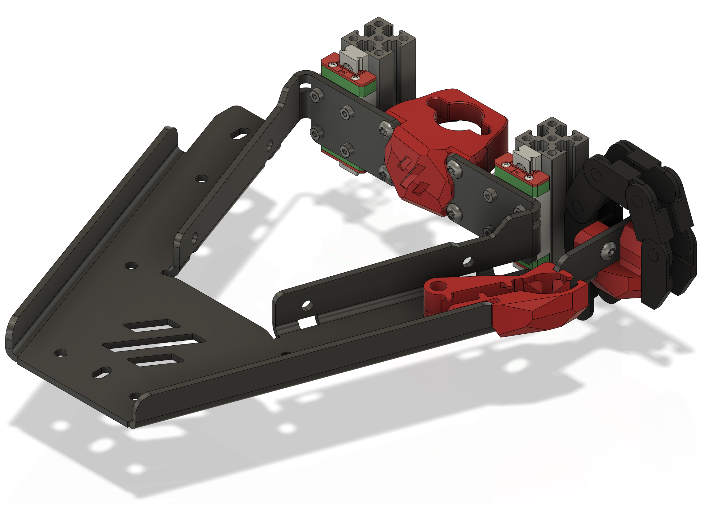
V0 Umbilical
GitHub: GitHub: https://github.com/VoronDesign/Voron-Hardware/tree/master/V0-Umbilical

The V0 Umbilical is a great mod included in this kit. It makes wiring much easier. All of the signals/power to the toolhead goes through a toolhead PCB breakout board, down to the back of the frame via a pre-made wire harness, through a second frame pcb breakout board and finally down to the SKR Pico.
Forbmot has precut and crimped most of the wires that go from the mainboard to the frame PCB. They've also made most of the wires that hook into the toolhead pCB the correct length as well.
Be sure to print the V0 Toolhead PCB mount and strain relief found here: https://github.com/VoronDesign/Voron-Hardware/tree/master/V0-Umbilical/STLs/V0.2
Wiring
General Wiring

This is a general wiring diagram for a Formbot V0.2(r1) kit. The only thing specific to the V0.2r1 is the Filament Runout Sensor (FRS) which gets plugged into the E0 Endstop input on the SKR Pico (next to the RGB/Neopixel). Otherwise it should serve pretty well as a general V0.2 build.
Since the V0.2 uses sensorless homing on the X-Y/A-B axes there's no endstops plugged into either of those inputs. In fact it's important to ensure that nothing is plugged into these inputs. Otherwise sensorless homing will not work.
Kirigami Bed Wiring
The Formbot kit does NOT include any wago or inline conectors!
The Kirigami Bed Frame alows splitting the wiring coming out of the bed so that the bed can be removed and worked on without being tethered to the printer.
Voron recommends using Wago connectors to allow easily disconnecting the wires. The Kirigami bed mod includes mounts for the Wago connectors.
Since the Formbot kit bed heater doesn't include an integrated thermal fuse it needs to be connected inline with one side of the bed wires.

Generic Formbot Wiring

An inline connector can be used to split the Thermistor wires under the bed.
Formbot Wiring + LDO Kirigami Wiring Kit

The LDO wiring kit includes 2 Wago mounts, a Thermistor breakout PCB and an LED PCB. A third wago is needed for the Formbot Thermal Fuse. The LDO V0 repo has stls for mounting its PCBs and the wagos. See the Kirigami Manual for more info.
BTT Pi Power
Formbot provides a precut, pre-crimped wire harness to go from the BTT SKR Pico's top right pins over to the BTT Pi V1.2's VCC and GND GPIO Pins. It provides 2 5V wires and a single ground. I think these were design to work with an original Raspberry Pi 3/4 which has it's GPIO on the right.

Since the BTT Pi has it's GPIO on the left the only way to get the wires over to those pins I had to stretch them across both boards. I felt the looked bad and worried about the tension.

To solve this I used their JST connector and repinned/crimped the some longer wires with Dupont connectors on the opposite side. With the wires longer I can pas them under the edges of the boards and through the cable management channel in the middle
BTT Pi to BTT SKR Pico Uart Communication
By default the Formbot kit connects the BTT Pi and SKR Pico by USB cable. This works well and is easily set up. However, it does limit the number of open USB ports to two (one is also taken up by the V0 Display). Since I also added a Klipper Exander and USB camera that meant all four ports were used. Leaving none for things like a USB Input Shaper Accelerometer.
Connecting the Pico and Pi via UART opens up a spare port again to help with this.
As noted in the section above the Formbot kit powers the the Pi via two +5V and a single GND set of wires going from a JST port on the SKR Pico to the GPIO Pins on the Pi. This is actually the UART comms header on the SKR Pico so we can easily add two wires (Green and Yellow in the Wiring Diagram) to free up the USB Port.
One end needs to be crimped with a JST XH connector and the other needs to be female duponts. Since this will only be transmitting data the guage isn't hugely important. You can use already crimped female-to-female Dupont bread board wires cut to size and crimped with a JST on one end. OR in my case take a pre-crimped JST wire and crimp a Dupont (harder to crimp) connector to the other end.
Then plug the extra two wires into the 5 pin JST connector housing on one end, and the Dupont connects onto the pins adjacent to the power pins on the Pi GPIO.

You'll need to shut down the Pi remove the SD Card, plug it into a computer and open the BoardEnv.txt file on the boot sector of the card. In that file change the line with console=and set it to console=serial to tell the Pi to talk via it's UART interface.
From there you can put reconfigure the Pico firmware to use UART0 GPIO1/GPIO0 for it's communication interface. Flash it via USB. Disconnect the USB and connect it via the new UART cable. Finally in your printer.cfg change the serial: portion of the MCU definition to /dev/ttyS0.
You should then be able to reboot the Pico and communication between the board and the Pi should work as normal
Products Used
Phaetus Dragon HF
This is an optional upgrade on some Formbot listings. It offers single hand nozzle tightening and much higher Max Flow Rate compared to the default Formbot V6 CHC nozzle.
Ali - https://s.click.aliexpress.com/e/_DlBBu2d You have to buy all the parts separately...

Bondtech 0.4 CHT Nozzle
This further increases the flow rate of the Dragon HF.
MatterHackers - https://www.matterhackers.com/store/l/bondtech-cht-m6-nozzle/sk/MEH3UZ0N?aff=7617

Fabreeko cPIF V0.2 Printed Parts
Fabreeko cPIF: https://www.fabreeko.com/collections/v0/products/voron-v0-2-s1-printed-parts-by-pif?variant=43678271570175
I found the cPIF parts pretty nice. I've since replaced a couple of of failed parts but I don't attribute the failures to the quality of the prints. More to some inherent issues in the part design

EP2 Grease
Product Links:
- Fabreeko Grease: https://www.fabreeko.com/collections/v0/products/mobilux-ep2-grease
- KB3D Grease: https://kb-3d.com/store/tools-equipment/497-linear-rail-carriage-lubrication-kit-mobilux-ep2-20ml-1645909620080.html
- West3D Grease: https://west3d.com/products/mobil-mobilux-ep2-10ml-filled-syringe-with-blunt-tip
I originally greased the rails with White Lithium lubricant but bought this and regreased them when I redid the frame.
GDS Time Fan Mini Stealthburner Fan Kit
- DFH Fan Kit: https://dfh.fm/products/voron-mini-stealthburner-fan-kit?_pos=7&_sid=66ce4f1ac&_ss=r
- Ali 3010 Axial: https://s.click.aliexpress.com/e/_Dl3Eglj
- Ali 3010 Blower: https://s.click.aliexpress.com/e/_DCMx5xj
The stock fans are probably the most noticable lower quality parts of this kit. I found the plastic a bit brittle and the leads didn't tuck into the their slots on the body. This cause them to get pinched when I put them in the Mini SB.
RC Style Hex Drivers
I found using any type of ball end and some not very sharp edged hex/allen drivers or bits resulted in stripped screws. In particular on the Frame and rails screws which I ended up screwing and unscrewing numerous times.
I tried my RC style hex drivers which have noticably sharper corners and noticed I didn't have any stripped screws.
Most will probably work well. Fabreek sells a couple different sets
Product Links:
- Fabreeko Set: https://www.fabreeko.com/products/fabreeko-precision-screw-driver-set-of-5?variant=38183379828934
- Ali 4PC Set: https://s.click.aliexpress.com/e/_Dn590Zb

Model Links:
- **Fabreeko Driver Set Gridfinity Holder: https://www.printables.com/model/270299-gridfinity-fabreeko-screwdriver-tool-holder
Flexible "Drone" USB Cable
This low profile USB cable was usefult to connect the Klipper Expander board to the BTT Pi V1.2. They can be configured with any type of end connectors. I used a 90 Degree Micro USB on one end and a standard Type A USB on the other

Ali Link: https://s.click.aliexpress.com/e/_DCxyxhJ
Ferrules
I try to use ferrules for every screw terminal whenever possible. If you don't have a ferrule set and/or crimper they're a great pickup for 3D Printer builders
Ali Link: https://s.click.aliexpress.com/e/_DnPAwm9
USB Camera
The BTT Pi V1.2 doesn't have a traditional Pi Camera connector. I used a common ELP 4K Pi style USB camera instead. The quality is pretty clear
Product Links:
Ali 4K 170: https://s.click.aliexpress.com/e/_DBiftLT
Model Link: https://www.printables.com/model/656391-voron-02-tophat-corner-camera-mount/

LDO Kirigami Wiring Kit
Description: "LDO Krirgami LED PCB, LDO Kirigami Breakout PCB, LDO Breakout Wire Kit, Wago 221-412 x 2 For use with Kirigami Beds"
Product Links:
- DFH Kit Full Wiring Kit: https://dfh.fm/products/voron-v0-kirigami-bed-wiring-and-led-kit
- West3D Kit PCB + Wagos: https://west3d.com/products/v0-2-kirigami-led-and-breakout-pcb-with-wagos
- Fabreeko LDO Kirgami LED + PCB: https://www.fabreeko.com/products/v0-2-kirigami-led-and-breakout-by-shammy
- Ali Wagos 5Pc: https://s.click.aliexpress.com/e/_DB8wSuh
- Ali Single NeoPixel PCB: https://s.click.aliexpress.com/e/_DdBNT49
Since the Formbot Kit only comes with the frame I bought this wiring kit to get close to what comes in the LDO kit.
Nevermore V6
Description: 3D Printed Activated Charcoal Filter
Mod Link: https://github.com/nevermore3d/Nevermore_Micro/tree/master/V6
Product Links:
- Fabreeko 5015 Fans: https://www.fabreeko.com/products/5015-blower-fan-by-honeybadger?_pos=1&_psq=50151&_ss=e&_v=1.0&variant=43628023152895
- DFH 5015 Fans: https://dfh.fm/products/5015-24v-dual-ball-blower?_pos=1&_sid=426120d23&_ss=r
- Ali 5015 Fans: https://s.click.aliexpress.com/e/_DBJycYD
- Ali 5pc Wagos: https://s.click.aliexpress.com/e/_DB8wSuh
- Fabreeko Activated Charcoal Pellets: https://www.fabreeko.com/products/nevermore-carbon?_pos=1&_sid=6691ede3b&_ss=r&variant=43205733449983
Printing ABS (as with most filament materials) can release VOCs (Volatile Organic Compounds) and has a noticabley more noxious smell than other materials like PLA. An active carbon filter can help clear absorb those orders/VOCs and move some air around the chamber for more efficient heating.
Klipper Expander Board
Board allows increased IO and power for mods and upgrades limited by BTT SKR Pico board
- Neopixels
- Nevermore Fans
- Chamber Thermistor

Product Links:
- Fabreeko: https://www.fabreeko.com/collections/v0/products/klipper-expander-board
- DFH: https://dfh.fm/products/klipper-expander-for-voron-3d-printers?_pos=1&_sid=9323da715&_ss=r
- Ali: https://s.click.aliexpress.com/e/_DdIuJM5
Fabreeko Honeybadger V0 Metal Toolhead Carriage
Product Link: https://www.fabreeko.com/collections/v0/products/v0-2-metal-toolhead-carriage-for-v0-2-by-honeybadger?variant=44164192338175
Variation: MGN7H
Requires - 4 M2x4 screws (for carriage mount), M3x8 (replaces rear M3x16 motor plate screw)
One of the parts I noticed failing was the X carriage. The hex nuts place on the front of the carriage started spinning in their slots. There was also a couple layer splits in the part when I removed it.

Rainbow Matchstick LEDs
Product Links:
- DFH: https://dfh.fm/products/rainbow-stick?variant=43340753666270
- West3D: https://west3d.com/products/rainbow-on-a-matchstick?_pos=10&_sid=57e17111c&_ss=r
- Fabreeko: https://www.fabreeko.com/products/daylight-disco-stick-rgb?variant=43841072922879
- Ali: https://s.click.aliexpress.com/e/_DdljyRf
Mounts Model By MapleLeafMakers: https://www.printables.com/model/408214-matchstick-diffusers

Becuase RGB LEDs
Rainbow Barf LED Skirts
Product Links:
- Fabreeko: https://www.fabreeko.com/products/rainbow-leds-pcb-by-whoppingpochard?_pos=1&_sid=cb992e68d&_ss=r
- West3D: https://west3d.com/products/steathburner-led-upgrade-rgbw?_pos=1&_sid=57e17111c&_ss=r
- DFH: https://dfh.fm/products/rainbow-barf-led-pcb-by-whoppingpochard-and-vinnycordeiro
Model Links:
- Mounts Model By MapleLeafMakers: https://www.printables.com/model/408741-v0-rgb-skirt-logo

Oriber Smart Filament Runout Sensor
Orbiter Extruder Project Link: https://www.orbiterprojects.com/orbiter-filament-sensor/

I thought it would be fun to modify the stock V0.2r1 FRS foot and use a smart sensor instead. With the use of a ball bearing and 2 push buttons the Orbiter sensor takes advantage of Klipper Macros to allow features like pausing/resuming, auto extruder heating, auto purging and quick unloading with the press of a button.
My V0 Orbiter Foot Model [WIP]: https://www.printables.com/model/602670-voron-v02r1-foot-orbiter-filament-sensor-wip
Product Links:
- Ali Sensor: https://s.click.aliexpress.com/e/_DeiGEDb
- KB3D Sensor: https://kb-3d.com/store/probes-switches/825-ldo-orbiter-v1-15-filament-sensor-kit-v22-1652646845812.html
- West3D: https://west3d.com/products/orbiter-filament-sensor-complete-kit-for-orbiter-extruder-v20-by-ldo-motors
- Fabreeko: https://www.fabreeko.com/products/orbiter-2-0-sensor?_pos=1&_sid=6352f305f
Mods Used
Stealth Handles
These replace two of the side panel holders and offer a clean looking way to easily move the printer around
Model Link By MapleLeafMakers - https://www.printables.com/model/481575-v0-stealth-handles

V0 Umbilical PTFE Guide + Molex Strain Relief
Model Link - https://www.printables.com/model/404594-v0-umbilical-ptfe-guide-and-molex-strain-relief

Bed Plate Guide
This is a little guide to make placing and aligning the PEI Bed Sheet easier.
Model Link - https://www.printables.com/model/497212-voron-v01-pei-sheet-positioning-jig

Cable Management Tracks
These are printable versions of the tracks that LDO and other kits include. I recomend printing them in PETG or a similar material that can flex a bit before snapping. I tried printing them in sever ABSs including Fusion Deep Water blue and the guide fingers were very brittle.
Voron User Mod Link: https://mods.vorondesign.com/detail/YTmSPTcWpctfTKQj3bOPg

V0 Hinged Spool holder and Rear Panel
Mod Link: https://www.printables.com/model/548771-voron-0-hinged-back-panel-w-hinged-filament-spool-
I found that I was frequently taking off the rear panel and often had to lay the printer on its back. This combo of mods makes it easy to work on the electronics of the printer and move it around without undoing a lot of screws.
Vector3D V0 Assembly Jigs
Link: https://github.com/AdamV3D/V3D-Voron-Mods/tree/main/v0/Assembly%20Jigs/STL
I found these Jigs by Adam from Vector3D very helpful. There are some for spacing elements like the linear rails when attaching them to the extrusion.

There's also jigs for spacing the Pulleys on the A/B Motor shafts which I found easier than the stock Voron tool

Tuning
To tune the printer I used a combination of:
- The Klipper Config Checks: https://www.klipper3d.org/Config_checks.html
- Voron Guide Startup Checks: https://docs.vorondesign.com/build/startup/
- Voron Sensorless Setup: https://docs.vorondesign.com/community/howto/clee/sensorless_xy_homing.html
- Andrew Ellis' Tuning guide: https://ellis3dp.com/Print-Tuning-Guide/
- OrcaSlicer's Calibration Prints/Tools: https://github.com/SoftFever/OrcaSlicer/wiki/Calibration
- CNC Kitchen Max Volumetric Flow Rate Test: https://hotend-flow-tester.netlify.app/
Things to tune
- Extruder Rotation Distance (Ellis)
- Build surface prep (Ellis)
- First slayer Squish (Ellis)
- Pressure Advance (Ellis/OrcaSlicer)
- Tuned EM/Flow-Ratio for the main filaments I use (Ellis/OrcaSlicer)
- Polymaker ABS/ASA
- MH Build PLA
- MH Build ABS
- Fusion Heavy water Blue
- Retraction (Ellis/Orca)
- Max Volumetric Flow Rate (Ellis/OrcaSlicer/CNC Kitchen)
- Motor Currents (Ellis)
- Input shaper (Klipper Docs)
- Axes Ressonance
- Belt Tension
- Ali Fysetc Portable Input Shaper - https://s.click.aliexpress.com/e/_DeZPSbP
Metadata
Owner
Metadata
Details/Documentation for the Formbot V0 Kit