SeitanClock
 SeitanClock copied to clipboard
NTP clock based on ESP 12F (ESP8266)
SeitanClock
NTP clock based on ESP 12F (ESP8266)
Features
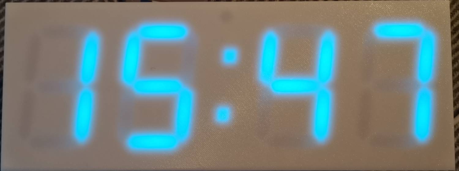
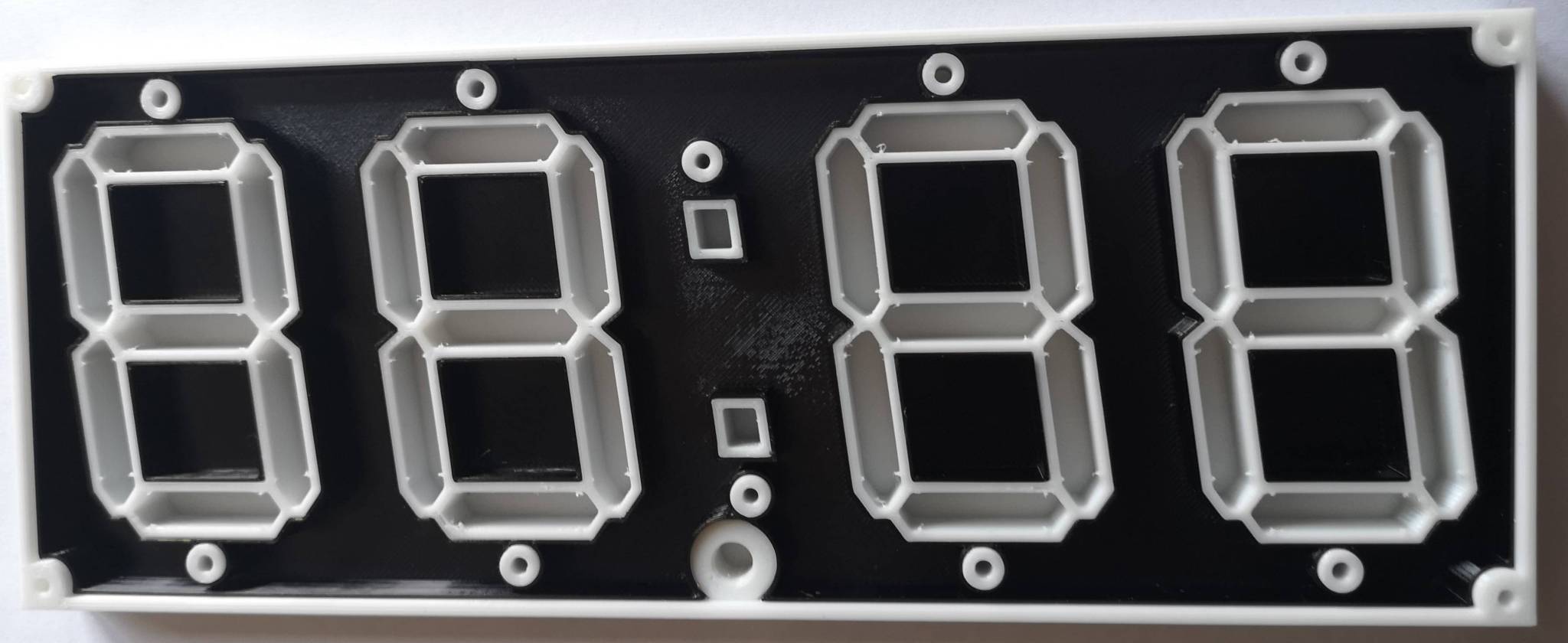
- 7 segment RGB display. Also suports stock i2c LED displays with HT16K33 driver.
- Clock synchronization via NTP over Wi-Fi.
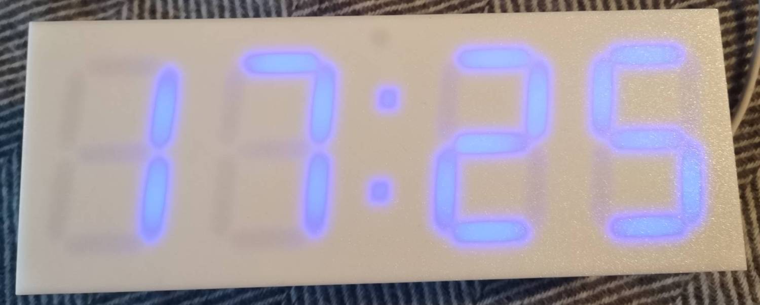
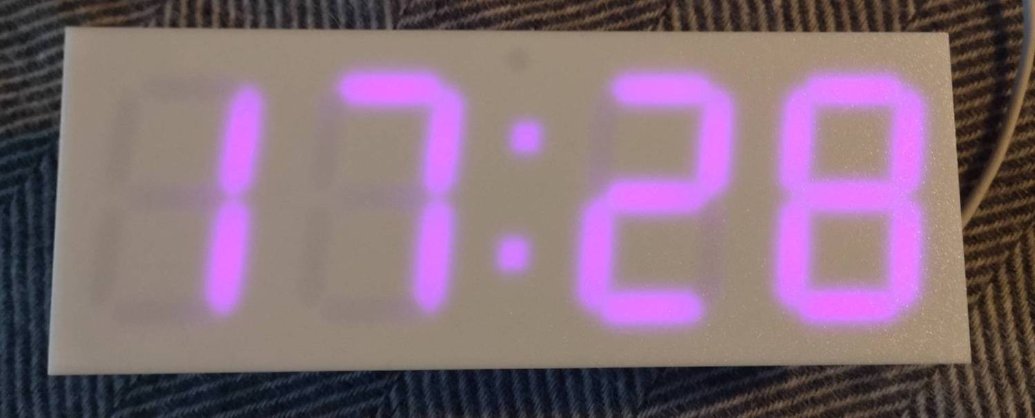
- Updates display intensity (and color) according to day and nigh time.
- Displays date and temperature.
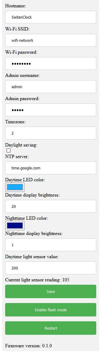
- Easy to use configuration portal.
- Firmware update via Wi-Fi.
Setup mode
Clock enters setup mode at first boot (when no Wi-Fi configuration is present yet).
To enter setup mode manually, power-cycle clock while pressing the button down.
Display will show StP message.
In setup mode clock acts as Wi-Fi hot-spot. There will be new Wi-Fi network SeitanClock-setup available. Connect to it with default password seitanclock. Point your browser to http://seitanclock-setup.local.
Note, that Android phones seems to lack MDNS support, so in case you are using Android phone, point your browser to IP instead: http://192.168.4.1. Default username for portal is admin, password admin.
Use setup portal to configure your clock. Save and reboot after.
Flash mode
Clock has a built-in feature to update its firmware via Wi-Fi. To get latest firmware:
- Get latest code release from https://github.com/Seitanas/SeitanClock
- Open it with Arduino IDE.
- Enter clock setup portal via
http://seitanclock.local - Push
Enable flash modebutton. Clock should displayFLAmessage. - Go to Arduino IDE -> Tools -> Port. Select
SeitanClock-flash.local(or if you have changed clock host name, useYOURHOSTNAME-flash.local). You may need to wait for a moment for network port to appear. Note, that clock and computer you are running Arduino IDE must reside in the same network segment. - Select Sketch -> Upload.
- Wait for upgrade to finish. Clock will restart automatically. Firmware upgrade leaves clock configuration intact.
Component list
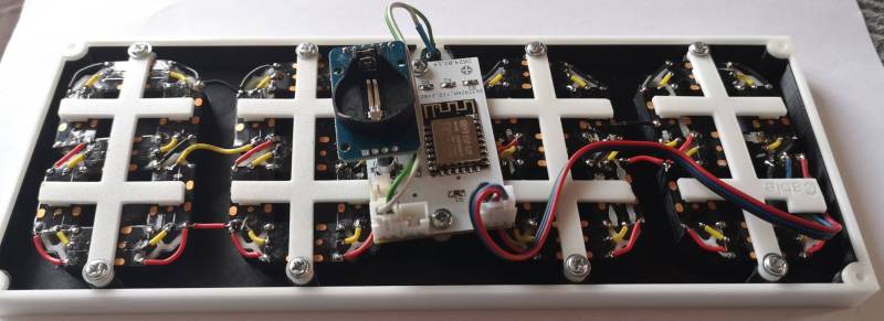
- 1m WS2812B DC5V, 144 IP30 RGB LED tape.
- 1pc DS3231 RTC module.
- 1pc GL5506 LDR photosensitive resistor.
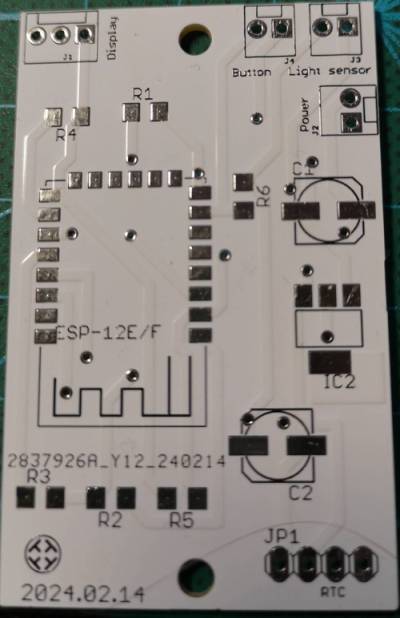
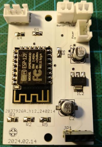
- 1pc ESP-12f module.
- 1pc 1.2K 1206 SMD resistor.
- 5pcs 10K 1206 SMD resistor.
- 1pcs AMS1117 (LM1117) 3.3 voltage regulator. SOT-223 package.
- 2pcs 47uF 0605 SMD electrolytic capacitor.
- 3pcs 2.54 mm pitch MOLEX 1x2 connector.
- 1pc 2.54 mm pitch MOLEX 1x3 connector.
- 1pc 2.54 mm pitch MOLEX 1x4 connector.
- 1pc 2.54 mm 1x4 female header.
- 1pc 6x6mm Square tactile switch.
- 1pc USB-C breakout board.
Electrical wiring diagram and PCB layout is done with CadSoft Eagle. You can find them in eagle folder.
Each display segment contains 3xWS2812B LEDs. Dots contain 1 WS2812B LED. Assemble segments in order as displayed in img/segment_order.jpg file.
3D models can be found in stl folder. And also on:
Printables
Thingiverse