ps2x2pico
 ps2x2pico copied to clipboard
USB keyboard/mouse to PS/2 interface converter using a Raspberry Pi Pico
ps2x2pico
USB keyboard/mouse to PS/2 interface converter using a Raspberry Pi Pico
 |
 |
 |
 |
|---|
Keyboard only (incl. PC-XT) variant: https://github.com/No0ne/ps2pico
PicoMiteVGA variant: https://github.com/No0ne/hid2cdc
PiKVM integration:
- https://docs.pikvm.org/pico_hid/
- https://docs.pikvm.org/pico_hid_bridge/
Usage
- Download
ps2x2pico.uf2from https://github.com/No0ne/ps2x2pico/releases - Copy
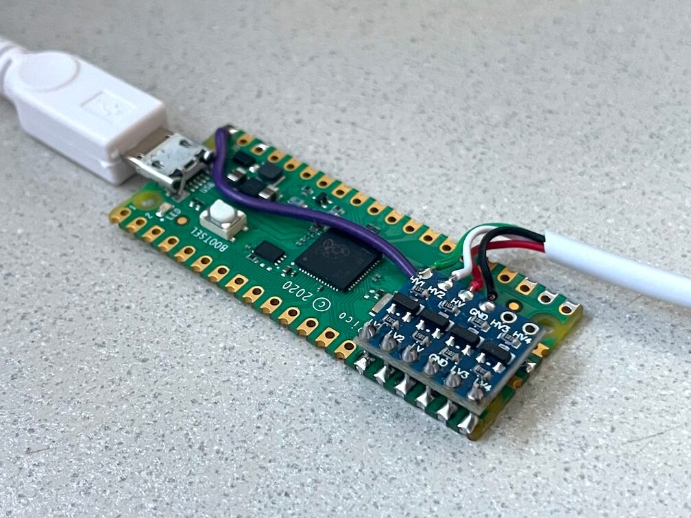
ps2x2pico.uf2to your Pi Pico by pressing BOOTSEL before pluggging in. - 3.3V/5V conversion is done using a bi-directional level shifter: https://learn.sparkfun.com/tutorials/bi-directional-logic-level-converter-hookup-guide/
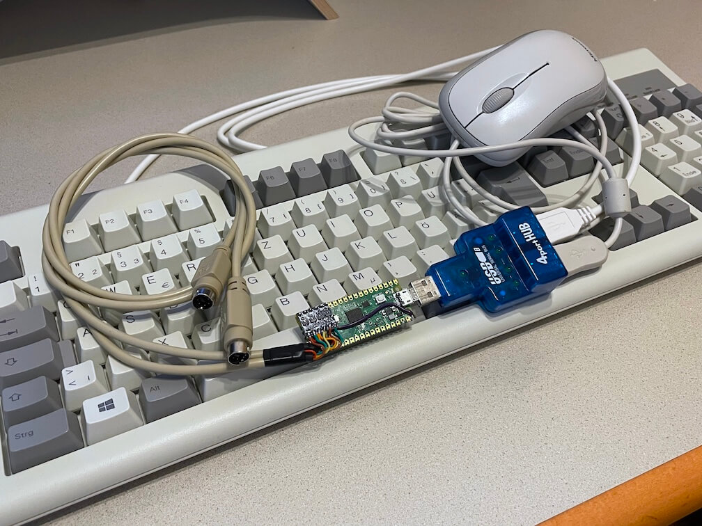
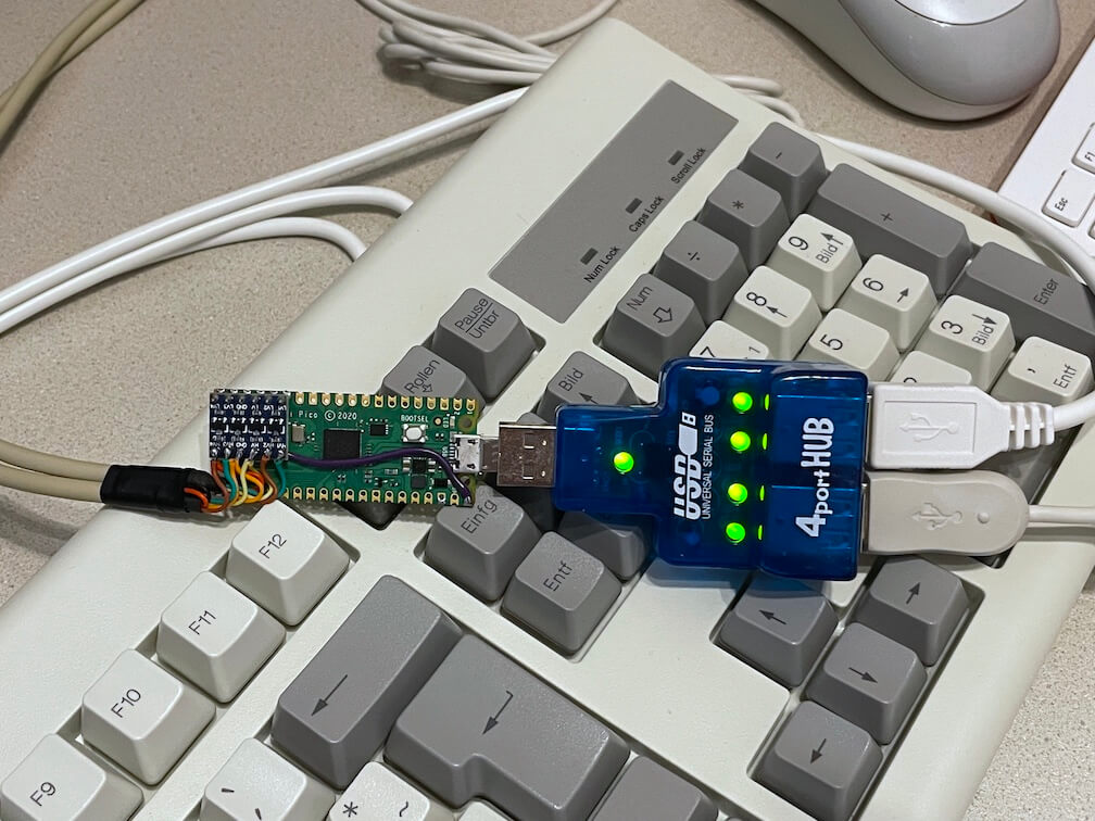
- Afterwards connect a USB keyboard and/or mouse using an OTG-adapter and optional USB hub.
- Also works with wireless keyboards and mice with a dedicated USB receiver.
                   _________________
                  |                 |
Pico GPIO11 ______| LV1         HV1 |______ PS/2 keyboard data
Pico GPIO12 ______| LV2         HV2 |______ PS/2 keyboard clock
Pico GPIO13 ______| LV          HV  |______ PS/2 5V + Pico VBUS
Pico    GND ______| GND         GND |______ PS/2 GND
Pico GPIO14 ______| LV3         HV3 |______ PS/2 mouse data
Pico GPIO15 ______| LV4         HV4 |______ PS/2 mouse clock
                  |_________________|
⚠️ Please note that some older motherboards have non-resettable fuses rated under 300mA.
Check the power consumtion of your keyboard/mouse/hub first before plugging in!
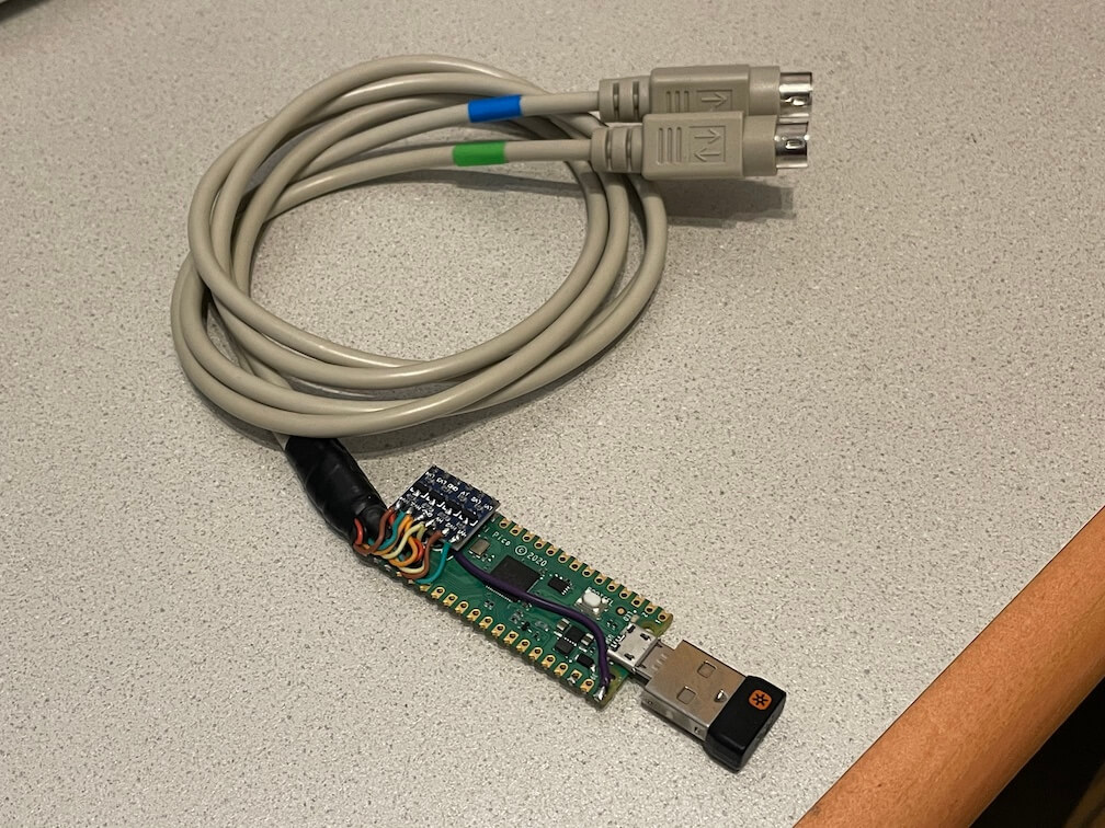
Pinout diagram
  Plug (device)        Socket (motherboard)
       _ _                     _ _
    =       =               =       =
  =  5  #  6  =           =  6  #  5  =
 =  3   #   4  =         =  4   #   3  =
 =             =         =             =
  =   1   2   =           =   2   1   =
    =       =               =       =
       ~ ~                     ~ ~
- Data
- unsed (mouse data on dualport)
- GND
- +5V
- Clock
- unused (mouse clock on dualport)
Troubleshooting
You can hook up a USB serial adapter to GPIO0 for additional debugging output. The serial settings are 115200 baud, 8 data bits and no parity. You can also use another Pico running the pico-uart-bridge for this.
⚠️ If you have a YD-RP2040 you need to bridge all three pads of the diode near the USB-C port as seen here: https://github.com/No0ne/ps2x2pico/issues/33#issuecomment-2066736110 Otherwise no power would be sent to the devices connected to the USB-C port.
Build
(update to the latest TinyUSB release first)
export PICO_SDK_PATH=/path/to/pico-sdk
cd $PICO_SDK_PATH/lib/tinyusb
git checkout 0.16.0

cd /path/to/ps2x2pico
mkdir build
cd build
cmake ..
make
Resources
- https://github.com/No0ne/ps2pico
- https://wiki.osdev.org/PS/2_Keyboard
- https://wiki.osdev.org/PS/2_Mouse
- https://wiki.osdev.org/Mouse_Input
- https://wiki.osdev.org/%228042%22_PS/2_Controller
- http://www-ug.eecg.toronto.edu/msl/nios_devices/datasheets/PS2%20Keyboard%20Protocol.htm
- http://www-ug.eecg.utoronto.ca/desl/nios_devices_SoC/datasheets/PS2%20Mouse%20Protocol.htm
- Archive.org links for the dead links in the pages above