pyroomacoustics
 pyroomacoustics copied to clipboard
Wrong signal amplitude (NLOS) when Y and Z of source and microphone positions match
Hi,
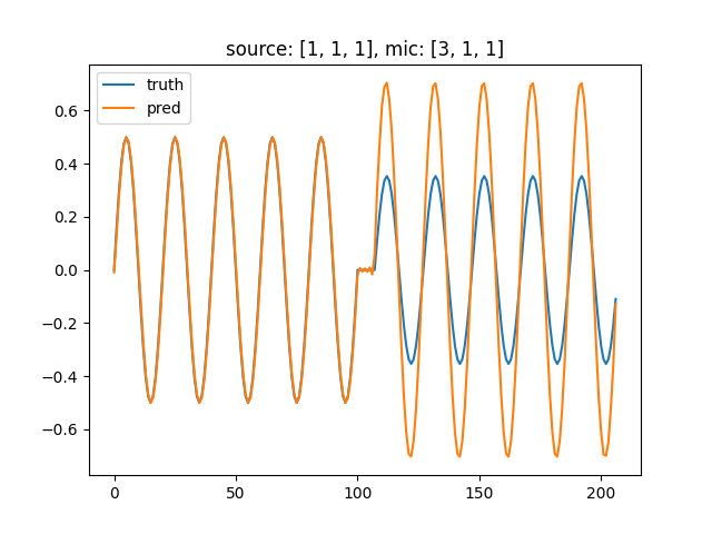
I noticed weird behaviour of the amplitude of the simulated signal in non-LOS situations: When the Y and Z coordinates of sound source and microphone match (e.g. source [1, 1, 1] and mic [3, 1, 1]), the amplitude of the signal is approx. twice as high as it should be (source amplitude divided by distance / length of signal path in metres).
Issue
considering the following room with one reflective wall and an obstacle to block the direct path:
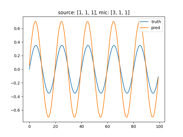
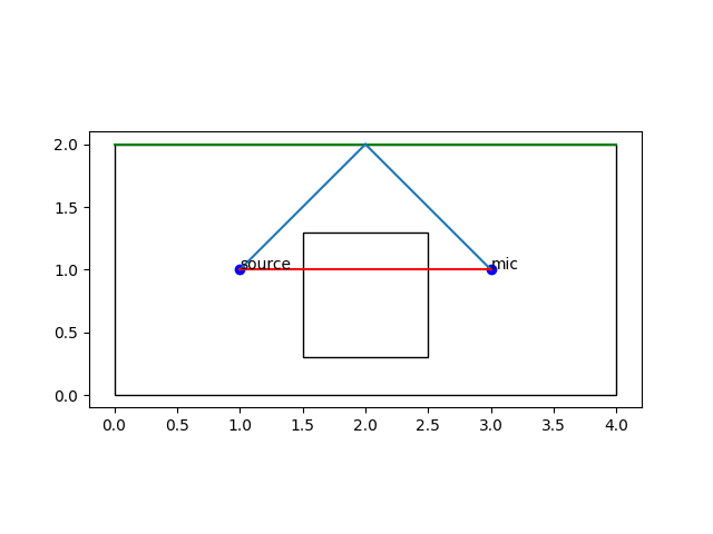 source and mic positions of [1, 1, 1] and [3, 1, 1] produce a wrong amplitude when comparing with manually computed reference (using a sine-wave of amplitude 1 as signal):
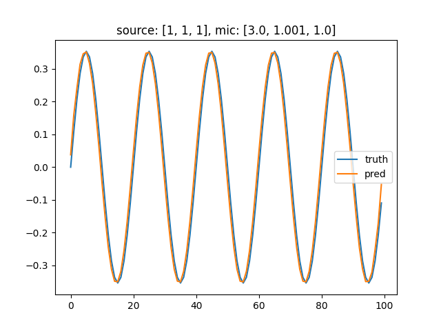
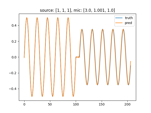
 changing either Y or Z coordinate of the microphone by 1mm gives correct results:
LOS plus NLOS
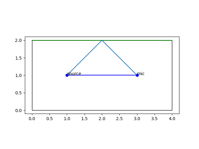
Repeating this with LOS plus NLOS (same room but without the obstacle) shows the same behaviour for the NLOS-component of the signal:
room:
 Y and Z matching:
 changing Y by 1mm:
Edge case
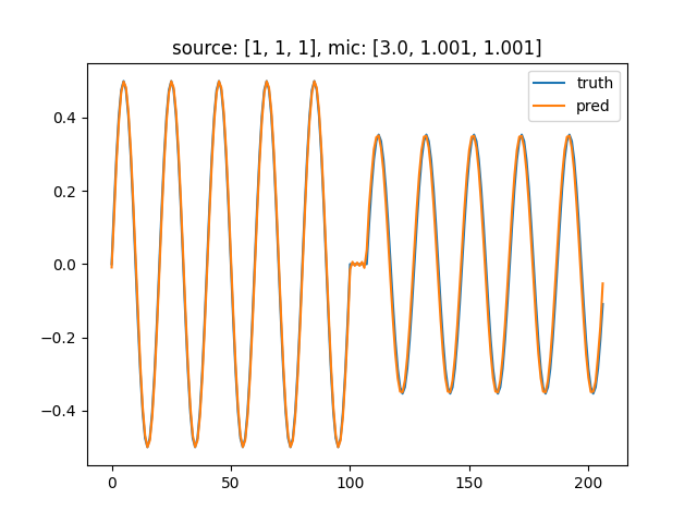
Changing both Y and Z usually also works:
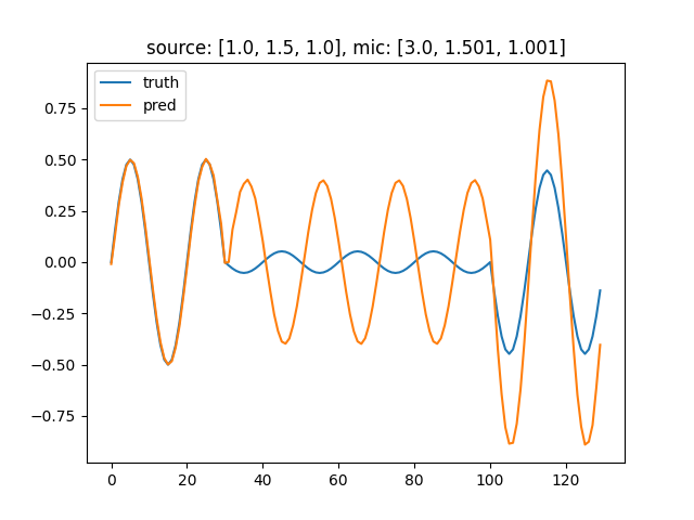
 However, at different Y position of 1.5, this again results in wrong amplitude for the NLOS component:
 Changing only one value still works here:
Raytracing
This also occurs when using raytraycing, although then the signal also shows some tolerable inaccuracies in the 'correct' cases.
Code to reproduce
Code and files (room STLs and material annotation files) for reproducing this issue: pyroomacoustics_issue_nlos_amplitude.zip
relevant code: (without room building and plotting)
`
USE_RAYTRACING = False
SAMPLING_RATE = 44100 SPEED_OF_SOUND = 343 # m/s sound_delay_samples_per_meter = 1 / SPEED_OF_SOUND * SAMPLING_RATE SOUND_DELAY_SAMPLES_CONSTANT = 40.5 # determined empirically, matches (pra.constants.get("frac_delay_length") / 2)
SIGNAL_LENGTH = 100
def compute_reflection_point(source: np.ndarray, mic: np.ndarray) -> np.ndarray: dist_x = mic[0] - source[0] source_to_wall_to_mic_to_wall_plus_source_to_wall = (2 - source[1]) / ((2 - mic[1]) + (2 - source[1])) source_to_reflection_point_x = dist_x * source_to_wall_to_mic_to_wall_plus_source_to_wall reflection_point = np.array([source[0] + source_to_reflection_point_x, 2, 1]) return reflection_point
def verify(signal: np.ndarray, source: np.ndarray, mic: np.ndarray, nlos_only: bool) -> Tuple[np.ndarray, np.ndarray]:
room = construct_room_from_file("room_nlos" if nlos_only else "room_los_plus_nlos", raytracing=USE_RAYTRACING)
# add source and mic and compute rir
room.add_source(source, signal=signal)
room.add_microphone(mic)
room.compute_rir()
room.simulate()
# compute reflection point of single signal path
reflection_point = compute_reflection_point(source, mic)
# plot room and signal path
plot_room_birdseye(source, mic, reflection_point, nlos_only=nlos_only)
# compute path length in metres
distance_nlos = np.linalg.norm(source - reflection_point) + np.linalg.norm(reflection_point - mic)
# compute and apply time-of-flight
offset_nlos = int(SOUND_DELAY_SAMPLES_CONSTANT + sound_delay_samples_per_meter * distance_nlos)

if nlos_only:
    # apply attenuation
    truth = signal / distance_nlos
    # extract relevant part of prediction
    prediction = room.mic_array.signals[0, offset_nlos:offset_nlos + len(signal)]
else:
    distance_los = np.linalg.norm(source - mic)
    offset_los = int(SOUND_DELAY_SAMPLES_CONSTANT + sound_delay_samples_per_meter * distance_los)
    offset_difference = offset_nlos - offset_los
    truth = (
            np.pad(signal, pad_width=[0, offset_difference]) / distance_los
            +
            np.pad(signal, pad_width=[offset_difference, 0]) / distance_nlos
    )
    # extract relevant part of prediction
    prediction = room.mic_array.signals[0, offset_los:offset_nlos + len(signal)]
return truth, prediction
def exec_one_test(signal, mic, nlos_only: bool, source: np.ndarray = np.array([1, 1, 1])):
truth, prediction = verify(signal, source=source, mic=mic, nlos_only=nlos_only)

ax = plt.gca()
ax.plot(truth, label="truth")
ax.plot(prediction, label="pred")
ax.legend()
plt.title(f"source: {list(source)}, mic: {list(mic)}")
plt.show()
def main(): # simple sine wave as test signal signal = np.sin(np.asarray(range(SIGNAL_LENGTH)) * np.pi / 10)
"""
basic issue: wrong signal amplitude ofr NLOS-path when Y and Z coordinates od source and mic match
"""
# nlos only, Y and Z of mic match source -> wrong amplitude
exec_one_test(signal, mic=np.array([3, 1, 1]), nlos_only=True)
# nlos only, Y differs by 1mm -> correct amplitude
exec_one_test(signal, mic=np.array([3, 1.001, 1]), nlos_only=True)
# nlos only, Z differs by 1mm -> correct amplitude
# exec_one_test(signal, mic=np.array([3, 1, 1.001]), nlos_only=True)
"""
also in LOS+NLOS, wrong amplitude for nlos part of signal
"""
# nlos plus los, Y and Z of mic match source -> wrong amplitude
exec_one_test(signal, mic=np.array([3, 1, 1]), nlos_only=False)
# nlos plus los, Y differs by 1mm -> nearly correct amplitude (perfect when not using raytracing)
exec_one_test(signal, mic=np.array([3, 1.001, 1]), nlos_only=False)
# nlos plus los, Z differs by 1mm -> nearly correct amplitude (perfect when not using raytracing)
# exec_one_test(signal, mic=np.array([3, 1, 1.001]), nlos_only=False)
"""
weird: at Y=1.5 (but not at Y=1.0) the issue also surfaces if Y and Z both differ by 1mm
"""
# nlos plus los, Y and Z differ by 1mm -> nearly correct amplitude (perfect when not using raytracing)
exec_one_test(signal, mic=np.array([3, 1.001, 1.001]), nlos_only=False)
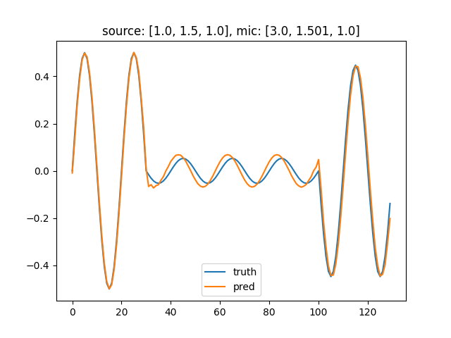
# nlos plus los, Y and Z differ by 1mm, different Y position -> wrong amplitude again
exec_one_test(signal, mic=np.array([3, 1.501, 1.001]), nlos_only=False, source=np.array([1, 1.5, 1]))
# nlos plus los, only Y differs by 1mm, different Y position -> nearly correct amplitude (perfect when not using raytracing)
exec_one_test(signal, mic=np.array([3, 1.501, 1]), nlos_only=False, source=np.array([1, 1.5, 1]))
`
Testing Environment
- python 3.9.2
- venv, with only the additional packages imported in the code file installed via pip
cycler 0.11.0 Cython 0.29.27 fonttools 4.29.1 kiwisolver 1.3.2 matplotlib 3.5.1 numpy 1.22.2 numpy-stl 2.16.3 packaging 21.3 Pillow 9.0.1 pip 22.0.3 pybind11 2.9.1 pyparsing 3.0.7 pyroomacoustics 0.6.0 python-dateutil 2.8.2 python-utils 3.1.0 scipy 1.8.0 setuptools 60.8.1 six 1.16.0 - Windows 10
I just took a look to your files. Thank you for all the details. One thing that is important is that all the wall normals should be pointing outward from the room. This means that for the obstacle in the room, the normals should be pointing towards the inside of the obstacle. Can you please check that this is the case ? If not, the walls may not be properly detected.
The normals point in the correct direction. The scaling of the normals seemed to be arbitrary, so I just recumputed them from the triangles (which are counter-clockwise when viewed from the 'outside', if that's relevant), but it didn't affect the output.
As the issue is also present in the LOS+NLOS scenario, where the room model is essentially a shoebox, I don't think the problem lies with the STL files. The materials used in this test are also just
pra.Material(energy_absorption=0.0, scattering=0.0)
and
pra.Material(energy_absorption=1.0, scattering=0.0).
Could it be an Issue that the STLs are in ASCII format?
I just noticed the face normals of the STL file are never used directly. I initialize the walls as per the code in ./examples/room_from_stl.py, which uses only the triangles, but not the normals. I guess it then relies on the vertex ordering.
Either that ordering is preserved from the stl file, or numpy-stl sets it according to the normal in the file. In any case, I verified both the normal and the vertex ordering (counterclockwise when viewed 'against' the direction of the face normal) are correct in my STL files, so that should be ruled out now.
So I think I found the cause of the error. I have mostly looked at the first example with source at [1, 1, 1] and mic at [3, 1, 1].
The problem comes from the reflecting wall being split into two triangles. This generates two image sources at the same location. Because the line of sight between the image source and the mic intersects the wall exactly on the boundary, the image source is marked as visible from for both triangles.
When you move the image source by a millimeter, then the path does not interesect on the boundary anymore and one of the image source is not visible from the microphone and correctly eliminated.
This is a corner case of the current implementation. I think you can solve the issue by manually merging the triangles into a single rectangular face. You can also solve this by trying to choose source/mic locations that are not too regular. Add a little bit of noise (e.g. a few mm) to the locations.
I just noticed the face normals of the STL file are never used directly.
You are right! The normals are determined from the order of the face corners.