pyleecan
 pyleecan copied to clipboard
[NF] Coupling with GMSH for 2D and 3D mesh
By reusing the same principal as for the FEMM coupling it should be simple to create a coupling with GMSH (http://gmsh.info/)
The main step would be to:
- Reuse the build_geometry method to generate the surface to draw (most of the geometry work is already done)
- add draw_gmsh methods to the Geometry object
- create new functions (matching FEMM ones) to generate the mesh
- For the mesh definition, we propose to assign a number of element for each line of each surface. It would be a comp_mesh_dict(element_size) method of machine that would call build_geometry and compute the length of each line to deduce the number of element on the line. It would return a dictionary[line label] =
. That dictionary can be then updated (as the FEMM_dict one) to tune the mesh. We have started to work on this function. - For 3D mesh we can then create a build_geometry_3D method for the machine and lamination to define (to begin) extrusion volume based on the build_geometry surfaces
First step is done: Slot object has now a get_surface_tooth that returns the lines of the tooth to draw (cf issue #26)
Regarding the commit: For now there is no "draw_gmsh" method in the Arc and Segment objects due to the fact that it would require to install gmsh even if the user doesn't want to use it. The same reflection is correct for FEMM. I think that we may need to add a dynamic import of FEMM and GMSH to make sure that they are imported only if the user is currently using the corresponding object. It could also be interesting to skip the corresponding unittest when the module are not available.
For now the coupling is a function to generate a 3D mesh from a LamSlot object. It can be interesting to extend it to Lamination / LamHole objects and maybe to add the ventilation. The coupling can also be improved:
- Possibility to set the number of element of each line (to use mesh_dict)
- Export mesh to several format (unv for instance)
- Merge all tooth 2D surfaces into one to have only one volume
- Possibility to include the skew in the extrusion
- If possible : create some set of nodes corresponding to the tooth tip
In the future this function will be included in fully automated model. For now it can be use in script to generate the mesh of a lamination.
Hi Pierre, is anyone helping with 2D gmsh? I would like to collaborate with it, I am familiar with gmsh-sdk and it would be great to get pyleecan exporting geometries in gmsh format.
Hello, Great idea to reopen this issue, indeed we can do much more with the GMSH coupling. For now, I don't think that anyone is working on this issue so your help is very welcomed !
Here is the current state of the coupling:
- Everything is gathered in the function: pyleecan/Functions/GMSH/gen_3D_mesh
- The principal of gen_3D_mesh is to call the method "get_surface_tooth" (or build_geometry with a symmetry) to get the surface object that correspond to a tooth. We then draw the tooth, set the mesh (size and element), duplicate the surface to get the 2D lamination, extrude the resulting surface and mesh.
- We have two test files that implement this function:
- Tests/functions/test_gmsh: The "normal and easy" case (3D mesh of a lamination)
- Tests/Plot/test_ICEM_2020: gather all the graph for our upcoming publication for ICEM 2020 with more advanced topologies (Fig 10: Line by line mesh definition ,Fig 11: several slot types and notches)
To improve this coupling the next step would be to generate the mesh of all the surfaces returned by the build_geometry method in 2D. For that I propose to create a new function gen_2D_mesh. This function would call build_geometry of a Lamination and (as for Functions/FEMM/draw_FEMM) would have a loop like:
for surf in surf_list:
    draw_GMSH(surf)
    setPhysicalName/Group(surf)
Once we will be able to draw and mesh several surfaces we should be able to merge gen_2D_mesh and gen_3d_mesh into one function.
What do you think of this new gen_2D_mesh function ? If you want I can give further details on the build_geometry method and the resulting surface object.
Thank you for your interest in the project, Best regards, Pierre
Hi Pierre,
I'm also interested in this feature, so any additional thoughts on the recommended implementation via the build_geometry method would be great!
Best regards,
Till
Hello Till,
I think that for the coupling we will have to add a method "draw_GMSH" to the object "Surface" and to Arc and Segment (as for the methods draw_FEMM). Thanks to the class generator we can now add these methods without adding the constraint for the user to install GMSH (there will be an error only if the user directly call draw_GMSH without GMSH installed). For these draw_GMSH methods, we will have to introduce arguments and return values for the current number of point and lines. Maybe we will have to create a list/dict to more actively track which point/line we have created if GMSH doesn't allow duplicates (which is an important thing to check). Then we will have to check that each point doesn't already exist before creating it.
Then there is the question: should we have this part of gen_3D_mesh adapted and included in draw_FEMM or should we keep it somewhere else:
    gmsh.model.geo.addCurveLoop(list(range(1, NLine + 1)), 1)
    gmsh.model.geo.addPlaneSurface([1], 1)
    gmsh.model.addPhysicalGroup(2, [1], 1)
    gmsh.model.setPhysicalName(2, 1, "Tooth")
Another interesting thing would be to be able to set a different mesh size for each surface. For the FEMM coupling we have the function comp_FEMM_dict that compute a different element size according to the machine dimensions. We then read this dict when drawing the surfaces to set the correct properties. We can do something simpler for the start: a dict argument with the surface Label as argument and the mesh_size as key. If a surface label is not in this dict, we use the mesh_size argument.
There is another important question: How GMSH behave if we add a point on an existing line (Winding inside a slot)? What about when we add a Line over an exiting Line (drawing a magnet within a Hole) ? On this topic we have started to work on a feature named "is_simplified" as an argument of Slot object build_geometry method that avoid returning "duplicates lines". We have never validated this feature but some slot/hole should already be compatible.
Finally we may have another difficulty: When we draw a LamHole machine, we first draw the two "circles" of the Lamination then we draw the holes within these circles. Should we use a boolean operation to remove the Holes from the Lamination surface ? Then we may need to implement a method to know if a point is inside any surface.
Here are some though that I have on this coupling that should help you. I may have missed some important part since I'm not very familiar with GMSH but if you have any trouble I should be able to help you find a workaround. As you will be two working on this feature please use this issue to coordinate your work to avoid doing some duplicated work. As the objective is to add a new function not already used in the code, merging your modifications along the development of this feature should not be an issue. So you can create pull request as soon as you have some part of the code.
Best regards, Pierre
Hi Pierre, Is there any way that build_geometry() does not return duplicated lines and points?. I am trying with the parameter is_simplified=True but it keeps returning duplicated points and lines when interfacing different surfaces. Best, Alejandro
On Fri, May 22, 2020 at 4:41 AM Pierre Bonneel [email protected] wrote:
Hello Till,
I think that for the coupling we will have to add a method "draw_GMSH" to the object "Surface" and to Arc and Segment (as for the methods draw_FEMM). Thanks to the class generator we can now add these methods without adding the constraint for the user to install GMSH (there will be an error only if the user directly call draw_GMSH without GMSH installed). For these draw_GMSH methods, we will have to introduce arguments and return values for the current number of point and lines. Maybe we will have to create a list/dict to more actively track which point/line we have created if GMSH doesn't allow duplicates (which is an important thing to check). Then we will have to check that each point doesn't already exist before creating it.
Then there is the question: should we have this part of gen_3D_mesh adapted and included in draw_FEMM or should we keep it somewhere else:
gmsh.model.geo.addCurveLoop(list(range(1, NLine + 1)), 1)
gmsh.model.geo.addPlaneSurface([1], 1)
gmsh.model.addPhysicalGroup(2, [1], 1)
gmsh.model.setPhysicalName(2, 1, "Tooth")
Another interesting thing would be to be able to set a different mesh size for each surface. For the FEMM coupling we have the function comp_FEMM_dict that compute a different element size according to the machine dimensions. We then read this dict when drawing the surfaces to set the correct properties. We can do something simpler for the start: a dict argument with the surface Label as argument and the mesh_size as key. If a surface label is not in this dict, we use the mesh_size argument.
There is another important question: How GMSH behave if we add a point on an existing line (Winding inside a slot)? What about when we add a Line over an exiting Line (drawing a magnet within a Hole) ? On this topic we have started to work on a feature named "is_simplified" as an argument of Slot object build_geometry method that avoid returning "duplicates lines". We have never validated this feature but some slot/hole should already be compatible.
Finally we may have another difficulty: When we draw a LamHole machine, we first draw the two "circles" of the Lamination then we draw the holes within these circles. Should we use a boolean operation to remove the Holes from the Lamination surface ? Then we may need to implement a method to know if a point is inside any surface.
Here are some though that I have on this coupling that should help you. I may have missed some important part since I'm not very familiar with GMSH but if you have any trouble I should be able to help you find a workaround. As you will be two working on this feature please use this issue to coordinate your work to avoid doing some duplicated work. As the objective is to add a new function not already used in the code, merging your modifications along the development of this feature should not be an issue. So you can create pull request as soon as you have some part of the code.
Best regards, Pierre
— You are receiving this because you commented. Reply to this email directly, view it on GitHub https://github.com/Eomys/pyleecan/issues/16#issuecomment-632574490, or unsubscribe https://github.com/notifications/unsubscribe-auth/AHYYMBM6NFDENHQRDMNW72LRSY3D7ANCNFSM4HGGTMXQ .
Hello Alejandro,
As I said, we haven't validated yet the parameter is_simplified (it was introduced for this purpose, but this is the first feature to actually use it). Can you share with us the Geometry you are trying to draw? We can help you by updating the corresponding build_geometry to make it work with is_simplified. Once the principal will be validated on a first geometry we can extend the corresponding principal on other geometry. For the points, I think that we will have to create a list with the existing point coordinates to avoid duplicates. We will have to check if every single point doesn't already exist before creating a new one.
Another way would be to create a method to "clean" an existing list of surface by removing the duplicate lines. We have an "Arc" method "is_on_arc" that can be redefined to "is_on_line" (a corresponding method need to be added for the Segment). That would enable to completely remove the "is_simplify" parameter (that ironically introduces a lot of complexity in build_geometry) and would work with any geometry.
Best regards, Pierre
Hi Pierre, I already implemented a couple of methods that dump the build_geometry() into a dictionary and all duplicated points and lines are removed (gmsh doesn't like them). Then, the line loops and surfaces are re-calculated in a gmsh- friendly manner. It's working so far for a rotor geometry with embedded magnets but I need to validate other rotors as well as stators (internal and external). Everything is coded in a draw_GMSH.py file with similar parameters as draw_FEMM().py, then we can discuss how to distribute the pieces of code. I haven't messed around with the airgap, sliding bands, boundaries and winding conductors yet. Also, how do you control the mesh size for FEMM? In gmsh is easier when drawing the points. Best,
On Mon, 1 Jun 2020, 15:27 Pierre Bonneel, [email protected] wrote:
Hello Alejandro,
As I said, we haven't validated yet the parameter is_simplified (it was introduced for this purpose, but this is the first feature to actually use it). Can you share with us the Geometry you are trying to draw? We can help you by updating the corresponding build_geometry to make it work with is_simplified. Once the principal will be validated on a first geometry we can extend the corresponding principal on other geometry. For the points, I think that we will have to create a list with the existing point coordinates to avoid duplicates. We will have to check if every single point doesn't already exist before creating a new one.
Another way would be to create a method to "clean" an existing list of surface by removing the duplicate lines. We have an "Arc" method "is_on_arc" that can be redefined to "is_on_line" (a corresponding method need to be added for the Segment). That would enable to completely remove the "is_simplify" parameter (that ironically introduces a lot of complexity in build_geometry) and would work with any geometry.
Best regards, Pierre
— You are receiving this because you commented. Reply to this email directly, view it on GitHub https://github.com/Eomys/pyleecan/issues/16#issuecomment-637056753, or unsubscribe https://github.com/notifications/unsubscribe-auth/AHYYMBI2ESTNDOND2BEM7LTRUP6JPANCNFSM4HGGTMXQ .
Hi Alejandro,
Great news for the cleaning methods :) Regarding the airgap, sliding bands it depend if we aim to generate the mesh of the machine or of a Lamination. For now the existing gen_3D_mesh is for a single Lamination. What do you want to simulate with this feature ? Regarding boundary conditions maybe we can start by imposing sym=1 or by drawing the full machine by duplicating a symmetrical part (sym>1 then copy/rotate). Regarding the winding: the surface that returns build_geometry correspond to a layer that can contains several conductors.
In gen_3D_mesh we use two methods to define the mesh size: First we use the "mesh_size" parameter to set the global mesh size for each point. Then we have this code:
   # Change the mesh size for each line
    if user_mesh_dict is not None:
        # Compute basic mesh_dict
        mesh_dict = tooth_surf.comp_mesh_dict(element_size=mesh_size, label="Tooth")
        # Overwrite basic mesh dict with user one
        mesh_dict.update(user_mesh_dict)
        # Apply the number of element on each line of the surface
        for ii, line in enumerate(tooth_surf.get_lines()):
            factory.mesh.setTransfiniteCurve(
                ii + 1, mesh_dict[line.label] + 1, "Progression"
            )
Each line of each surface should have a label, we can provide a dictionary[line label] = nb element to define a different mesh size for each line (cf Test/Plot/test_ICEM_2020.py/test_gmsh_mesh_dict). When a dictionary is provided, we compute the "basic mesh_dict" that contains all the lines label with the corresponding number of element to match mesh_size. For now there is no label for the point but it is something that we can introduce to create a mesh dict [point label] = mesh size. Additionally, in FEMM we have the function "comp_FEMM_dict" that computes different mesh sizes for each part of the machine according to the machine dimensions.
Best regards, Pierre
Hi Alejandro,
I would like to know how things are going on your side regarding the 2D/3D mesh for GMSH. Do you have further questions or do you need any help ? In the near future (once the electrical module will be validated) we plan to work as well on this feature. Do you think that you can push your modifications to a forked pyleecan so we can collaborate with you ?
In issue #104 we were talking about the coupling with xfemm that would also require a function to clean the geometry. Do you think that you can do a pull request with the "cleaning function" to help us on this issue as well ?
Best regards, Pierre Bonneel
Hi Pierre, I completed the rotor and started the stator lamination but I haven't had the chance to continue due to the lack of time. The cleaning function is working but has been validated with only one IPM rotor. I want to complete the gmsh mesh including conductors and airgap because I have a coupling with Elmer in one of my repo that I would like to implement in pyleecan too.
So far , all my code is in one single file and not yet cleaned up to share. I anticipate a couple of weeks before it's ready. I don't have issues implementing the function so it's used on issue #104 too. However, the function should be implemented at lamination level (stator, rotor), probably within build_geometry() call because it needs the information of all the surfaces in order to remove duplicated lines and points while keeping the right orientation of the surface loop.
I am moving between houses this weekend and won't be able to progress either but I hope that next week I will have some time for programming. Best, Alejandro
On Thu, 18 Jun 2020, 05:39 Pierre Bonneel, [email protected] wrote:
Hi Alejandro,
I would like to know how things are going on your side regarding the 2D/3D mesh for GMSH. Do you have further questions or do you need any help ? In the near future (once the electrical module will be validated) we plan to work as well on this feature. Do you think that you can push your modifications to a forked pyleecan so we can collaborate with you ?
In issue #104 https://github.com/Eomys/pyleecan/issues/104 (#104 https://github.com/Eomys/pyleecan/issues/104) we were talking about the coupling with xfemm that would also require a function to clean the geometry. Do you think that you can do a pull request with the "cleaning function" to help us on this issue as well ?
Best regards, Pierre Bonneel
— You are receiving this because you commented. Reply to this email directly, view it on GitHub https://github.com/Eomys/pyleecan/issues/16#issuecomment-645905252, or unsubscribe https://github.com/notifications/unsubscribe-auth/AHYYMBOZ75UXZ4NGH3XTDNLRXHOEJANCNFSM4HGGTMXQ .
Hi Alejandro,
Great news that you managed to do the rotor lamination :) We were also thinking about working on the coupling with Elmer one day. We will be happy to help you integrating it into pyleecan.
Regarding the cleaning method, I think that it can be included in Functions/Geometry. Then I see two possibilities:
- Calling it at the end (before the return) of every single build_geometry (with a parameter to disable the call for the plot machine methods)
- Calling it only in the GMSH/xfemm coupling after calling the machine build_geometry.
Have a nice week-end :)
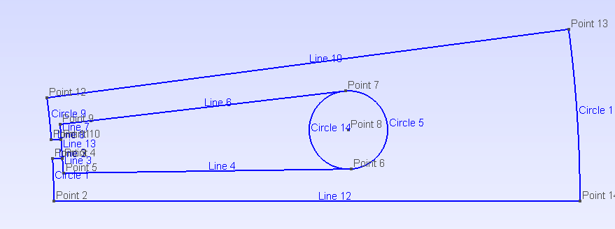
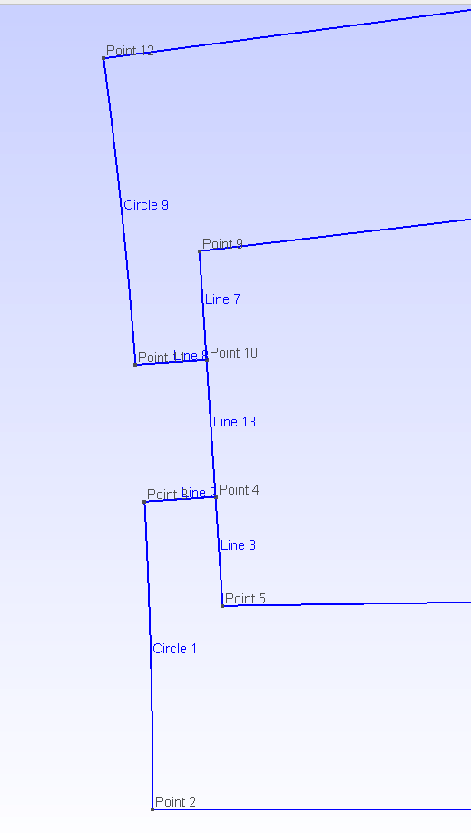
Hi Pierre, I have an issue and don't know how to proceed. Please see the attached images of a slot (IPMSM_A.json), the cleaning method that I implemented for removing duplicated points and lines after calling build_geometry() fails when operating on slots with windings. GMSH does not like overlapping or intersecting lines, so before drawing a new point or line, I search among the points and lines already drawn to use them instead.
The way I can recognize a line/arc already drawn is because their beginning or ending points coincide with the new ones. It was working fine until I tried to use it on the above mentioned stator with windings. The problem is that the winding has a Segment going from point 5 to point 9 (in the picture), these points are already present because they were drawn for the slot so the new Segment reuses the point 5 and 9, however the line is redrawn because there is no existing line between 5 and 9, that creates overlapping lines in this particular slot without wedges (line 13 overlaps lines 3 and lines 7).
Is there any way that the winding returns 3 lines (5 to 4, 4 to 10 and 10 to 9) rather than only one line (5 to 9) that overlaps the slot ones?
Thanks,
Alejandro
On Thu, Jun 18, 2020 at 12:12 PM Pierre Bonneel [email protected] wrote:
Hi Alejandro,
Great news that you managed to do the rotor lamination :) We were also thinking about working on the coupling with Elmer one day. We will be happy to help you integrating it into pyleecan.
Regarding the cleaning method, I think that it can be included in Functions/Geometry. Then I see two possibilities:
- Calling it at the end (before the return) of every single build_geometry (with a parameter to disable the call for the plot machine methods)
- Calling it only in the GMSH/xfemm coupling after calling the machine build_geometry.
Have a nice week-end :)
— You are receiving this because you commented. Reply to this email directly, view it on GitHub https://github.com/Eomys/pyleecan/issues/16#issuecomment-646132287, or unsubscribe https://github.com/notifications/unsubscribe-auth/AHYYMBLOJWHTV6KSJKK6J4LRXI4IJANCNFSM4HGGTMXQ .
Hi Alejandro,
I can't see any attached file to your response :-/ Can you try to upload directly on Github ?
EDIT: Thanks for the edit :-)
Hi Alejandro,
I see two ways to handle this case:
- The "easy" way would be to update the method build_geometry_wind of SlotW11 to return the 3 Lines instead of one (I can work on that if you want). The issue with this method is that we would need to update all slots to make sure that the error does not occur.
- The clean way would be to be able to detect that the lines are overlapping and merge them properly. For that we have the Segment method intersect_line that returns 2 points if the lines are overlapping.
I expect that you will also have some issue with the following case:
 When we split the winding in rad, we add a point on an existing segment. The existing segment should then be split in two parts. I think that we can detect that by using the Line method "is_on_line" (the is_on_arc method of Arc must be renamed to is_on_line) to check if the begin or end point of a line are not on other lines.
Finally, it is a bit tricky but I think that we should change the build_geometry method of LamSlotWind to include these clean-up before duplication the slot and winding surfaces. That way we have Zs times less lines to handle and the cleaning should be faster and more efficient. I can contribute on this part as well.
Best regards, Pierre
Hi All,
I have so far these files: draw_GMSH.py generates the Gmsh file by calling build_geometry() in rotor and stator objects. There is also a test_gmsh2.py that tests the method. I decided to keep the same function parameters as draw_FEMM() method, but obviously most of them are not used yet.
One of the issues right now is the winding, this example works because the wedge height is larger than zero, so the lines from tooth surface don't overlap with lines from winding. Also, it's a single layer winding so the lateral lines are shared between tooth and winding.
Errors will show up with a double layer winding.
Let me know whether or not I submit a pull request for this 'work in progress' code, also advise if the code should be placed in a different file than pyleecan/Functions/GMSH/draw_GMSH.py.
Best,
Alejandro
pyleecan_gmsh.zip

Hello,
Thank you for your work :) Even if it doesn't work with every machine, this is an important step :)
Here are few hints about how to go further:
- Regarding the parameters, the function draw_GMSH mesh should be simpler than the FEMM one since we don't need to define the current yet. Then we can remove the parameters is_mmfr, is_mmfs, type_calc_leakage, type_BH_stator and type_BH_rotor. Maybe one day we will add them back (it will depend how we will define the corresponding simulations).
- is_remove_vent, is_remove_slotS and is_remove_slotR should be used the same way as in draw_FEMM: it remove some complexity from the lamination before calling build_geometry.
- I think that we can also include a "is_lam_only" (maybe is_lam_only_R, is_lam_only_S ?) parameter to be able to remove the winding and/or the magnets.
- We may also need to be able to draw a single lamination. Maybe we can also take into account that stator or rotor can be None ? Or we can provide a different function for a single lamination.
- line 278 shaft can be None
- Everything is handled with the GMSH_dict, can you provide a documentation about what it contains and how we should use it ? Can you also add some comments to your code so we can help you handle the double layer case ?
I think that you can do a pull request with your code: as it is not included yet in any module it won't break anything and other people will be able to contribute to your function. Indeed you can use the path pyleecan/Functions/GMSH/draw_GMSH.py (once your function will be complete, I think we will remove "gen_3D_mesh"). Regarding your test, you can redefine it as a pytest (you can take Tests/Plot/test_ICEM_2020.py - test_gmsh_mesh_dict as an example) and extend the existing Test/Function/test_gmsh method.
Best regards, Pierre
Hi Pierre, Could you advise what is the best way to implement the air gap mesh in Gmsh? What functions can I use to get the lines to draw air gap surfaces? And could you also advise on the boundary conditions? Since I want to create a function to export the gmsh file and create the physics for Elmer solver. Best, Alejandro
Hello Alejandro,
Currently in FEMM the air gap mesh is drawn to use sliding band technique: http://www.femm.info/wiki/SlidingBand We just need to draw two circles (or arc circles if there is spatial (anti)-periodicity) in the airgap which delimits sliding band, and then assign (anti-)periodic boundary condition on both circles. Sliding band prevents from physically drawing and closing the airgap mesh for each rotor position, thus the mesh is the same for all rotor position and this should reduce numerical errors due to remeshing for each rotor position. Do you know if this feature exists in Elmer ? I've looked into it and found this particular example: http://www.elmerfem.org/forum/viewtopic.php?t=4652 but I don't know if it's relevant.
Concerning boundary conditions, they are stored as property of lines (segments / arc) and they are assigned in the model when drawing all lines using draw_femm.py methods belonging to segment and arc classes. Since I don't know how boundary conditions are handled in Elmer, in particular if it is possible to include them in the gmsh file, I can't say if the way boundary conditions are assigned in FEMM is the most convenient for Elmer. In any case you could implement methods to export line properties in Elmer format afterwards, and feed Elmer with a gmsh file containing the geometry/mesh and an Elmer file containing physics.
Best regards, Emile
Hi Emile, Yes, sliding band is also possible in Elmer, what I usually do is define physical groups in gmsh and then set the conditions in the Elmer settings file. However, my initial doubt is more related with pyleecan methods available to obtain the lines and their boundary conditions, including those for the air gap. I would like to be advised on what is the best strategy currently available in pyleecan (based on FEMM coupling) to set those conditions without having me to re-implement a method to calculate the boundaries based on the symmetry/periodicity and what lines belong to each boundary. With that information, I will define line physical groups in Gmsh that can be translated to Elmer-mesh-compatible via ElmerGrid tool. Thanks, Alejandro
On Thu, 3 Sep 2020, 09:06 EmileDvs, [email protected] wrote:
Hello Alejandro,
Currently in FEMM the air gap mesh is drawn to use sliding band technique: http://www.femm.info/wiki/SlidingBand We just need to draw two circles (or arc circles if there is spatial (anti)-periodicity) in the airgap which delimits sliding band, and then assign (anti-)periodic boundary condition on both circles. Sliding band prevents from physically drawing and closing the airgap mesh for each rotor position, thus the mesh is the same for all rotor position and this should reduce numerical errors due to remeshing for each rotor position. Do you know if this feature exists in Elmer ? I've looked into it and found this particular example: http://www.elmerfem.org/forum/viewtopic.php?t=4652 but I don't know if it's relevant.
Concerning boundary conditions, they are stored as property of lines (segments / arc) and they are assigned in the model when drawing all lines using draw_femm.py methods belonging to segment and arc classes. Since I don't know how boundary conditions are handled in Elmer, in particular if it is possible to include them in the gmsh file, I can't say if the way boundary conditions are assigned in FEMM is the most convenient for Elmer. In any case you could implement methods to export line properties in Elmer format afterwards, and feed Elmer with a gmsh file containing the geometry/mesh and an Elmer file containing physics.
Best regards, Emile
— You are receiving this because you commented. Reply to this email directly, view it on GitHub https://github.com/Eomys/pyleecan/issues/16#issuecomment-686475882, or unsubscribe https://github.com/notifications/unsubscribe-auth/AHYYMBKGZEX4FJR37DUEBHLSD6IDLANCNFSM4HGGTMXQ .
Hi Alejandro,
Ok so I think you can have everything you need already in the build_geometry and the FEMM coupling.
In the build_geometry of Lamination (and daughters) classes, some labels are assigned on specific lines, including those which will have boundary conditions.
In the init.py of the Functions/FEMM/ folder, these labels are linked to the name of the respective boundary conditions that are set in FEMM, eg :
# dictionary matching boundary condition with line in FEMM
boundary_prop = dict()
boundary_prop["airgap_line_1"] = "bc_ag1"
boundary_prop["sliding_line"] = "bc_ag2"
boundary_prop["airgap_line_2"] = "bc_ag3"
boundary_prop["Rotor_Yoke_Radius"] = "bc_A0"
boundary_prop["Stator_Yoke_Radius"] = "bc_A0"
boundary_prop["Rotor_Yoke_Side"] = "bc_r1"
boundary_prop["Stator_Yoke_Side"] = "bc_s1"
where "bc_ag1", ..., "bc_s1" are the name of boundary conditions that are created in create_FEMM_boundary_conditions.py
In the draw_FEMM methods of segments and arcs, the boundary condition is assigned to the corresponding label. The draw_FEMM methods of segments and arc are called by the draw_FEMM of surfaces which is called by the draw_FEMM function.
Concerning sliding band, the method get_sliding_band enables to draw the sliding band and assign boundary conditions.
I hope this will help you!
Best regards, Emile
Hello @ajpina ,
I did some code optimization in #229. Hope you don't mind. Maybe you could also review the PR, if you got some time.
Are you currently working on the draw_GMSH function, since I found some issues and things to improve.
- The sliding bands seem to be wrong since they are full circles (for sym=1) that overlap the inner lamination. But I don't what the actual properies of the sliding band should have to be conformal to Elmer.
- I think it would be good to have some better control over the machine parts that have to been drawn, e.g. is_lam_only_S and is_magnet. So if you have plans to do some changes to draw_GMSH it would be great if you could also address this points. Otherwise I will try to do it.
Best regards, Sebastian
Hi Sebastian, You are absolutely right, the sliding band has not been implemented yet for the full model (sym=1) and has the same code when I copied the function from FEMM get_sliding_band(). For symmetries other than 1 it's working according to Elmer approach. There are still plenty of work to do in draw_GMSH, so far I am working on the boundary conditions and air box to start the work on Elmer coupling. I am sure there are still issues in windings with dual layer due to the overlapping/broken lines between windings and slots if you want to take a look. Also, I have double checked geometries with only outer stators for SPMs and IPMs, so I am pretty sure that it might fail with other tricky geometries that I haven't tried. Feel free to improve the code as you wish. Best, Alejandro
Hello @ajpina ,
I guess you need 2 different boundaries for each lamination for the magnetic coupling, e.g. "Rotor_Yoke_Left" and "Rotor_Yoke_Right", while there is actually only one boundary label "Rotor_Yoke"?! I may change this, since I think I also need some additional labels for the structural coupling.
Best regards, Sebastian
Hi @SebGue , These are the boundaries that I am including in my next PR, please use them:
boundary_prop = dict()
boundary_list = ["MASTER_ROTOR_BOUNDARY",
"SLAVE_ROTOR_BOUNDARY",
"MASTER_SLAVE_ROTOR_BOUNDARY",
"SB_ROTOR_BOUNDARY",
"MASTER_STATOR_BOUNDARY",
"SLAVE_STATOR_BOUNDARY",
"MASTER_SLAVE_STATOR_BOUNDARY",
"SB_STATOR_BOUNDARY",
"AIRGAP_ARC_BOUNDARY",
"VP0_BOUNDARY"
]
boundary_prop["int_airgap_line_1"] = "MASTER_ROTOR_BOUNDARY"
boundary_prop["int_airgap_line_2"] = "SLAVE_ROTOR_BOUNDARY"
boundary_prop["int_sb_line_1"] = "MASTER_ROTOR_BOUNDARY"
boundary_prop["int_sb_line_2"] = "SLAVE_ROTOR_BOUNDARY"
boundary_prop["Rotor_Yoke_Side"] = "MASTER_SLAVE_ROTOR_BOUNDARY" # it needs to be found out later
boundary_prop["int_sb_arc"] = "SB_ROTOR_BOUNDARY"
boundary_prop["ext_airgap_line_1"] = "MASTER_STATOR_BOUNDARY"
boundary_prop["ext_airgap_line_2"] = "SLAVE_STATOR_BOUNDARY"
boundary_prop["ext_sb_line_1"] = "MASTER_STATOR_BOUNDARY"
boundary_prop["ext_sb_line_2"] = "SLAVE_STATOR_BOUNDARY"
boundary_prop["airbox_line_1"] = "MASTER_STATOR_BOUNDARY"
boundary_prop["airbox_line_2"] = "SLAVE_STATOR_BOUNDARY"
boundary_prop["Stator_Yoke_Side"] = "MASTER_SLAVE_STATOR_BOUNDARY" # it needs to be found out later
boundary_prop["ext_sb_arc"] = "SB_STATOR_BOUNDARY"
boundary_prop["ext_airgap_arc_copy"] = "AIRGAP_ARC_BOUNDARY"
boundary_prop["airbox_arc"] = "VP0_BOUNDARY"
This code will be added in Functions/GMSH/__init__.py
I found out that pyleecan does not differentiate the master/slave lines for rotor or stator so I had to add an additional processing to identify "Rotor_Yoke_Side" or "Stator_Yoke_Side" and turn them into either Master or Slave boundaries.
I am sure you can use the same boundaries above for others solvers. If you can solve the master/slave lines and differentiate those directly in build_geometry(), that would be great because no additional code would be needed in draw_GMSH(). Please let me know your thoughts.
Best,
Alejandro
Hello @ajpina ,
could you also commit your actual work in progress code so I can have a look? For the differentation of the boundaries I will add e.g. "Left" and "Right" to the names so you don't have to care. For the actual names of the gmsh boundaries, it's okay for me now and we could also change them later just in case. BR Sebastian
Hi @SebGue, I just submitted my work in progress in PR #232 for you to take a look. Best, Alejandro
Happy New Year!
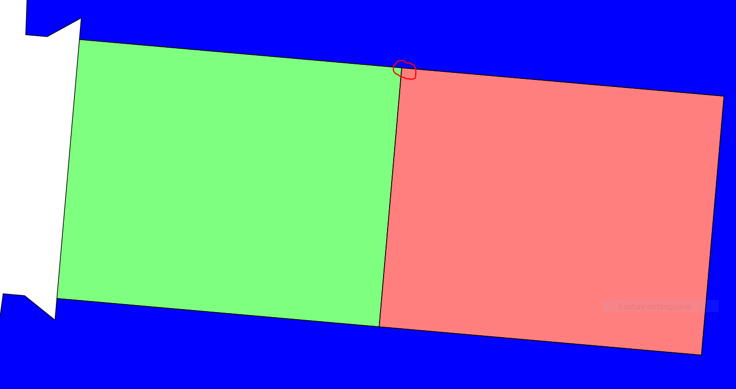
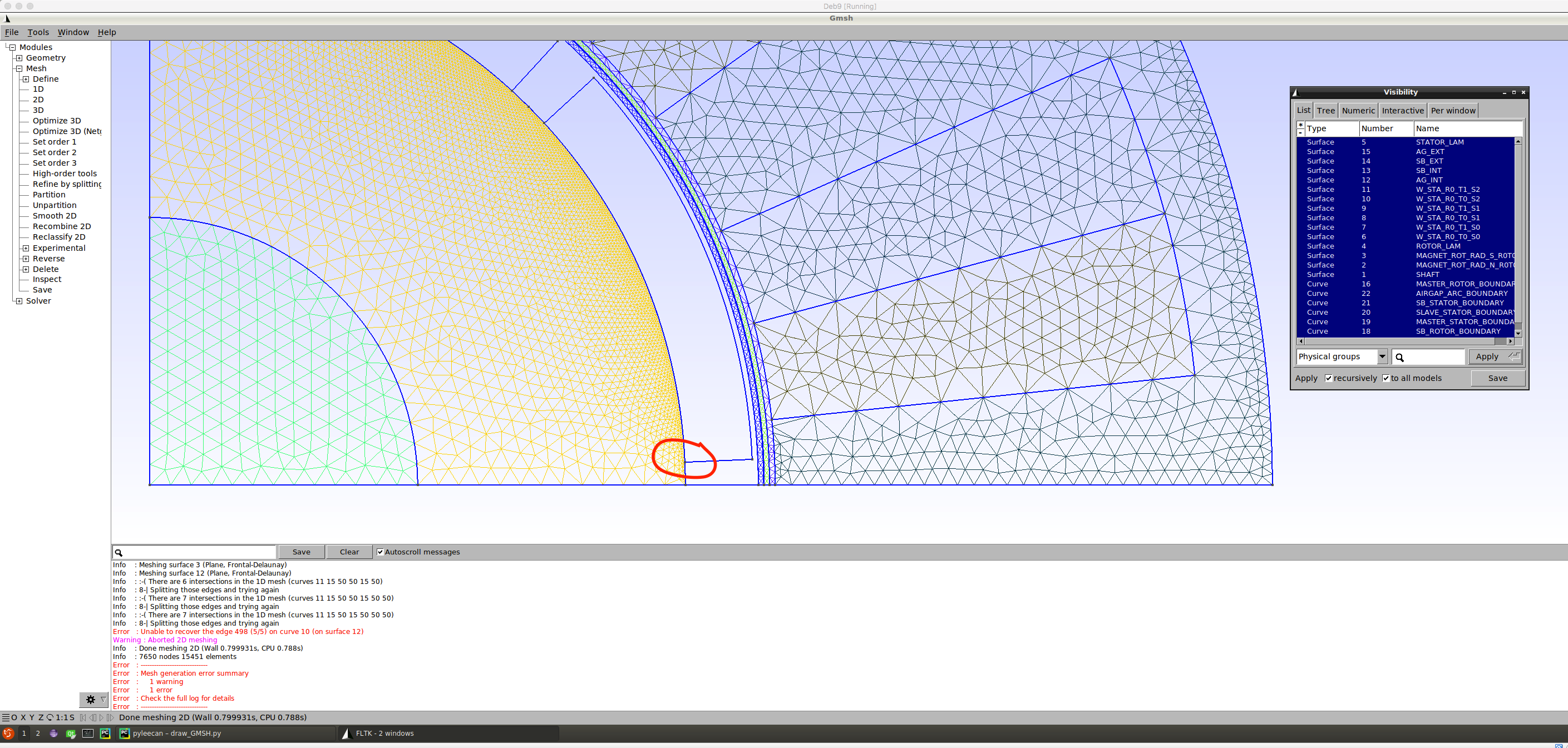
I am having issues handling geometries of Surface Permanent Magnet machines, it happens that when the magnet arc length is shorter than pole pitch, overlapping lines are created by build_geometry(). Rotor lam outer arc is created with a length equals to pole pitch and PM line (shorter arc) is placed on top. This makes the meshing process fail in gmsh and hinders the drawing of air gap regions.
 I have been taking a look at the draw_FEMM() (FEMM coupling) and don't see any treatment for this, it seems that luckily FEMM takes care of it internally (please let me know if I am wrong).
- Is there any way that rotor lamination surface uses magnet lines when calling build_geometry() rather than creating new overlapping lines?
- Is there anyone currently working on this lines simplification that we talked before https://github.com/Eomys/pyleecan/issues/16#issuecomment-654091243 ?
If rotor and magnets share the lines, meshing is simpler (conformal), otherwise the magnets are floating in the air gap region (which is physically plausible having glue been modeled) but unpractical due to the tiny gap.
In the zoomed in picture you can better see the issue: (magnet, rotor and air gap lines don't intersect)
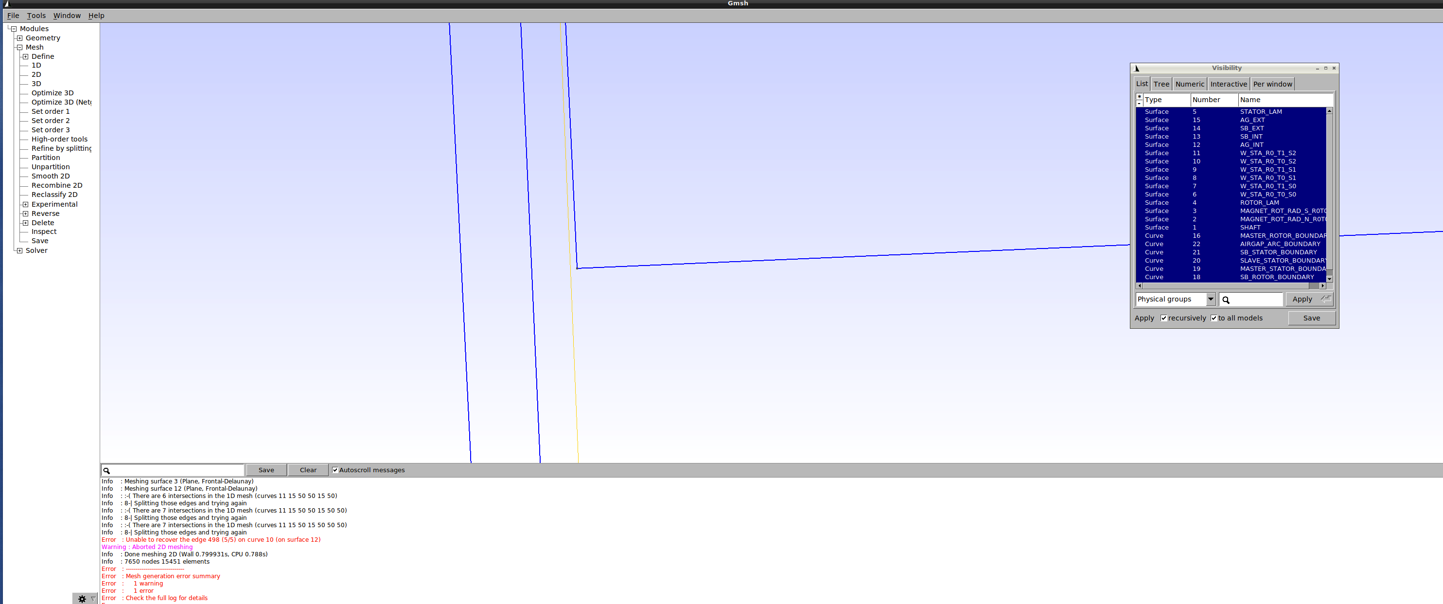
Best, Alejandro