SensorModbusMaster
 SensorModbusMaster copied to clipboard
Add BOM (Bill of Materials) for Modbus-Mayfly-Wing hardware
Could a component list be added - or a pointer to where to find it.
Its nice to see the gerbers and be able to generate a PCB from them - but I can't see any BillOfMaterials that is traditionally used to list partnumbers.
Personally, with my schematics I usually make an identifier indication visible on the schematic, but I guess everyone is different.
When I try and list the parts in Eagle 9.1 it doesn't show them.


@neilh10, thanks for posting this issue. I'll try to get the Mayfly Modbus Wing documentation completed next week
That would be great - as I've got the Wing PCB made up and have a time window when I could try it. Seems like it needs Mayfly Rev0.5 with separate 3.3V sw (I have Rev0.4) Deducing from pics seems like the Wing PCB is a routing PCB, and requires two other PCBs - could be- Step up 12V https://www.pololu.com/product/2117 Tx/Rx RS485 https://www.makerlab-electronics.com/product/ttl-to-rs485-hw0519-module/ but if so I couldn't get a response about hw0519 from maker-lab in the Philippines. Many thanks for any insights.
@neilh10, yes you've basically figured it out. Here are additional details.
- Print Modbus-Mayfly-Wing PCB using these Gerber files
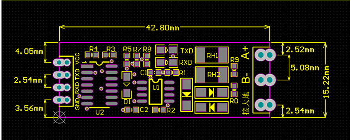
- Attach this WINGONEER TTL To RS485 Adapter 485 Serial Port UART Level Converter Module 3.3V 5V from Amazon.
- Attach either the Pololu 12V Step-Up Voltage Regulator U3V12F12 or the Pololu 9V Step-Up Voltage Regulator U3V12F9, depending on your needs.
- You will probably need a capacitor to handle the initial power surge of starting up the sensor. Here are the three that we used:
- CAP ALUM 220UF 20% 10V RADIAL, for the lowest power demand sensors.
- CAP 470 UF 20% 10 V, which was the minimum size that would power a YosemiTech Y511 Turbidity sensor with a brush.
- CAP ALUM 680UF 20% 6.3V T/H, which was barely the minimum size that would power a YosemiTech Y4000 Sonde with a brush. We usually used two of these, or one of these plus a 470 uF capacitor.
- Various headers, screw terminals from DigiKey:
| Part Number | Description | Unit Price |
|---|---|---|
| WM11221-ND | CONN HEADER VERT 3POS TIN | 0.442 |
| WM4002-ND | CONN HEADER 4POS .100 VERT TIN | 0.3 |
| 732-5316-ND | CONN HEADER 3 POS 2.54 | 0.088 |
| 609-3214-ND | CONN HEADER 20POS .100 STR 15AU | 0.706 |
| ED10563-ND | CONN TERM BLOCK 2.54MM 4POS PCB | 0.8204 |
- We also used Grove ports from Seeed Studio.
Thanks that helps a lot. I got an order in for the WINGONEER RS485 - possibly the last one. So for the parts from Digikey - https://www.digikey.com/short/jwjd1z
Thanks for what has worked for the input C1 and C2 capacitors into 12V stepup. When the mayfly boost turns on for the 5V_SW , the Pololu 12V switches on, which then supplies the RS485 instrument when it is at its lowest impedance and consumes the most current. Of course if you have a wiper, that is a load spike when already active. Initializing conditions always interesting - hardware or software :). The Pololu 12V step up specified 1.4A switch input - the switch current pulse is typically the same no matter what the load is. The boost chip often varies the switching frequency based on the load but sometimes the switch current - either way good to be able to handle the specified 1.4A switch current. Also its independent of what the Mayfly boost is a capable of as its the input switch current to the Pololu. So I would think that C1/closest to Pololu would be a ceramic to take the switch current and then C2 would be low ESR buffer but capable of supporting sizeable ripple current. C2 has to be filled by the Mayfly boost so actually doesn't want to be too large, and overall Mayfly boost can probably only supply a continuous ~0.3A@5V So based on that, and power supply issues are painful to debug (had my fair share), the leads are TH 2.5mm, after some research on Dk I'm inclined to try C1 reasonably large uF ceramic at leads=2.5mm, and over 10V rating C2 lowest uF Electrolytic at 1.0A @100Khz leads=2.5mm
C1 ceramic FG11X7R1C226MRT06 22uF 16V X7R Dk$1.04 C2 Electrolytic Wurth 860080274013 680UF/10V ripple=1.0A@100Kz 68mOhms Dk$0.38
@bschulz1701, who helped design the shield, provided us those capacitor part numbers. Those are what we've been using successfully on more than 20 units that @fisherba and I have deployed in the wild this summer.
My understanding is that C1 and C2 are in parallel, so that the order or what goes were doesn't matter, and I've put capacitors in either or both positions. Also, because the capacitors are on the input side of the Pololu boost converter, they only see 5V of power, so anything over 5V will work fine, even when the sensor is getting 12V.
Let us know what your experiences are!
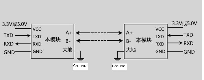
One warning: Modbus stop bits are high, which leaves the AltSoftSerial transmit pin (5 or 6) at 3.3V when the sensor power shuts down. This then bleeds through RS485 converter into the switched power rails, which then interfers with the startup of some other sensors, such as the MaxSonar. For a solution, see ModularSensors Issue "Add to Modbus an AltSoftSerial "flush" or "end" function, to set pins low #140" for the coding solution.
Hello @neilh10 !
Just wanted to chime in quick and echo what Anthony said and try to clarify a few things.
- Firstly, I have added the part numbers for the connectors to the Eagle file, along with the part numbers for the 680uF capacitors, so hopefully this will clear things up in the future. I can also add a more comprehensive BOM connected with the parts Anthony mentioned.
- In this case we have been using identical capacitors and not being concerned about their position
- I see where you are getting at with your capacitor examination, in this case both the Mayfly and the Pololu Boost regulator have appropriate low ESR ceramic caps placed very close to the switching and regulator sources, there should handle all of the appropriate ripple rejection we desire. The reason we designed this board was basically as a workaround to use the Mayfly as a power source for the Yosemitech sensors. At DC the mayfly can deliver sufficient power without issue, however it was discovered that there is a spike on startup (and more aggressively so on the brushed systems) which caused a brownout of the Mayfly power system (there should be documentation I put together in this repo analyzing the problem if you are curious). Ideally, a parallel power supply with greater current driving capability would be used, but it was desired to run fully off the mayfly system. To allow this we are using C1 and C2 purely as a capacitive bank to provide the additional current required (beyond the capabilities of the mayfly) during this short (several ms) spike. Since the caps are simply acting as a capacitive bank, we are less concerned about their ESR and ripple rejection since they should generally not be acting as filter capacitors, and therefore went with a pair of the larger electrolytics since we found in testing that this quantity of capacitance was required for the largest Yosemitech SONDE.
Hope this is helpful, and I will do my best follow up with any other questions you may have
Hi @bschulz1701 - thanks for wingboard design, and the overview and the updates. Yeah I didn't have a boost cct/parts for Pololu, or the BOM/parts for the Mayfly. The Pololu web references the destructive LC load spikes on ideal switchon, from the low ESR capacitor in the circuit, (which doesn't represent the Mayfly 5V_SW) https://www.pololu.com/docs/0J16 They recommend a solution high ESR large capacitor to give some impedance in the input I guess - which is what you have. I've got my parts ordered :) so I'll give it a run. I usually do a quick check on the DC response of power supplies when I first try them, (so that I learn) so I could publish what I see. I'm interfacing to a Keller Nano level, which is only specified for a max draw of 22mA - but not sure what its turn on power surge is - so not anticipating any problems after all the testing that you seem to have done.
I'm not using a brushed system, - but I'm curious where the documentation is about what you think is causing the brownout, and whether it was with the Mayfly 0.5 and large LiIon (2Ahr+)?, I may have been one of the people identifying the Mayfly 0.3 brown out condition (https://github.com/EnviroDIY/EnviroDIY_Mayfly_Logger/issues/1). For the Mayfly 0.5, the power path seems well connected. The 5V_SW input has a separate 3.3V_SW rated for 0.5A, derived from Vin ~4V which is delivered through Q1/FDN340P (rated 2A) from a charged LiIon (4.2V?). So seems would be headroom on the Vin rail. Seems to be good gnd between J4-pin20 and LIPO Jpx GND. I always layout my PCBs with ground 1st (if 2L) and then power, and with switchers or when switching power trace the power loops.
Hello @bschulz1701 - just a quick checkin. I have the parts and the SMC RS485. "WINGONEER TTL To RS485 Adapter 485 Serial Port UART Level Converter Module 3.3V 5V" last one on Amazon.
On the SMC RS485 board, now that I physically have one, the RS485 driver is labeled MAX485. Looking up that part number on Digikey, it would appear to be Maximum https://datasheets.maximintegrated.com/en/ds/MAX1487-MAX491.pdf.
Checking Vcc spec its defined for 4.75-5.25V. Just wondering if I've got the right parts. Thanks.
@neilh10, I'm glad to here that you got the last WINGONEER TTL To RS485 Adapter 485 Serial Port UART Level Converter Module 3.3V 5V from Amazon.
For the record, there are about a dozen companies that sell that exact same RS485 adapter board, so you always have other options. There are also about 3 other similar models of RS485 adapter boards also for sale. I "discovered" that specific model when I YoseimTech sent me a "converter" box with my first shipment, and we opened it up to find that board, along with an oversized 12V power adapter inside the big converter enclosure. So that's what I started using, and now @fisherba and I have used successfully on dozens of deployments for over a year now. That said, @SRGDamia1 has also successfully used a few alternative RS485 adapter boards, but the first one we tried was both smaller and less expensive.
Despite my efforts, I was never able to find any good documentation for our favorite RS485 adapter board. The best I found was here: https://www.amazon.com/gp/product/B06XHH6B6R#feature-bullets-btf or here https://www.amazon.com/SMAKN®-Adapter-Serial-Converter-Module/dp/B010723BCE/.
I also got these saved these images from a website that no longer exists:

I know that it says that it can only handle signal logic level shifting from 3.3V to 5V, but YosemiTech sent us a working setup with 3.3V to 12V logic level shifting, and our deployments are all at either 9V or 12V. So it works! Also, when using the Mayfly, we need to power the board with 3.3V so that the signal it returns is 3.3V logic. And that works very well too!
It sounds like you used a magnifying glass to get a part number of the main chip, which might be the MAX485. I know that chip is used on many of the other boards out there, but I think it needs extra components to make it useful, which is why I started looking for full boards.
Hello @aufdenkampe thanks for the detailed response. I saw some of the variety of sellers - I'm assuming since its the same picture they all use the sources are distribution channels rather than manufacturers. They all have the RS485 chip label blank. I have another 2 ordered of the SMAKN. The question I was raising, is that assuming the chips markings are genuine MAX485 from Maxim, then its only specified for 5V... and its powered at less than 5V, from 3.3V. So it may not work - though sounds like your experience has been good. So it was just checking if it had been considered. :) Of course powering it from 5V means the Rx into the mega1284 would need protection. (I use series 100K resistor into CMOS for this type of protection) The 12V is the sensor powering industry standard and is separate from the RS485 I'm an electronic engineer and as part of that is ensuring specs for products I design if 10,000 are produced they will all work. :) All the SMC-RS485 boards source variants are nice for their integrated functions - auto DE (with looks like D, R & C) and specifically it looks like an industrial board with all the high voltage/lightening protection built in -especially TVS. Of course it doesn't work unless the "RS485 Ground" follows lightening and grounding procedures and connected to a solid earth ground. I've seen a number of devices hit by lighting, but its usually specific geographical areas that are lightening prone (Wy, Fl, Oh..) The embedded LEDs are also valuable feedback and probably don't waste too much power. In the past I've used the sparkfun RS485 (https://www.sparkfun.com/products/10124) & Olimex MOD-RS485 - both which requires DE. The sparkfun has SP3485 which is specified 3.3V However there is also a chip now that does Auto DE MAX13487EESA+ https://datasheets.maximintegrated.com/en/ds/MAX13487E-MAX13488E.pdf
BTW I stress tested the Pololu 12V Step-Up Voltage Regulator U3V12F12, with capacitors that I specified and a bench +4.7V supply, and for simple switching into a resistive load it behaved flawlessly at 12V. I did use the CER 22uF TH leads to hold the switcher to the wingboard, so kept the CER cap as close as possible. Even went to 387mA@12V though that required 1220mA @ 4.7V line. If there is any limitation then its the method of switching the power - either on the input or output.
Again many thanks for the detailed response and for all the amazing software. I'm trying to figure out how to import https://www.envirodiy.org/topic/newbie-mayfly-setup-for-rs485-sensor-to-internet/ to a platformio/visual studio
Pulling out my magnifying glass, I can see "WK 1604" written on them, along with a logo that looks like a 4-lobbed flower or lopsided butterfly. If you figure out the full identity, let us know.
The other two chips are:
- "MAX485 ESA +17DN", for the chip near R1 & R2
- "NXP 74HC04D DNXH17 DX UnG8322", for the chip below R3 & R4. Give us some links to these part numbers too!
By the way, different batches of these boards have different labeling on them (including swapping R1 & R2), and some of them don't have any markings on the chips.
@aufdenkampe @mammutserver Given the part info Anthony was able to provide (thanks for noting the quirky symbol by the way, quite helpful! that is the diode branding for Vishay by the way) this appears to be the TVS diode, both from correlating the part markings and the specifications are appropriate for that kind of application.
https://www.digikey.com/products/en/circuit-protection/tvs-diodes/144?k=SMAJ6.5A&k=&pkeyword=SMAJ6.5A&sv=0&v=112&pv7=2&sf=0&quantity=&ColumnSort=0&page=1&pageSize=25
Feel free to give me a shoutout if you're trying to reverse-engineer/decode anything else on that board. I have built a similar design so I have a good idea of everything going on there.
Just checking if anybody is see any problems with the various versions of the RS485 hybrids.
I have one WINGONEER TTL that is working, - with RS485 SO8 chip number scrubbed. Has been working perfectly in a beta situation for months. Now trying to build another system.
The WINGONEER is no longer available, so I had purchased some others that are not working. I built these some time ago, so traceability is bit of problem but I think they are SMAKN version, labeled RS485ESA SO8 chip.
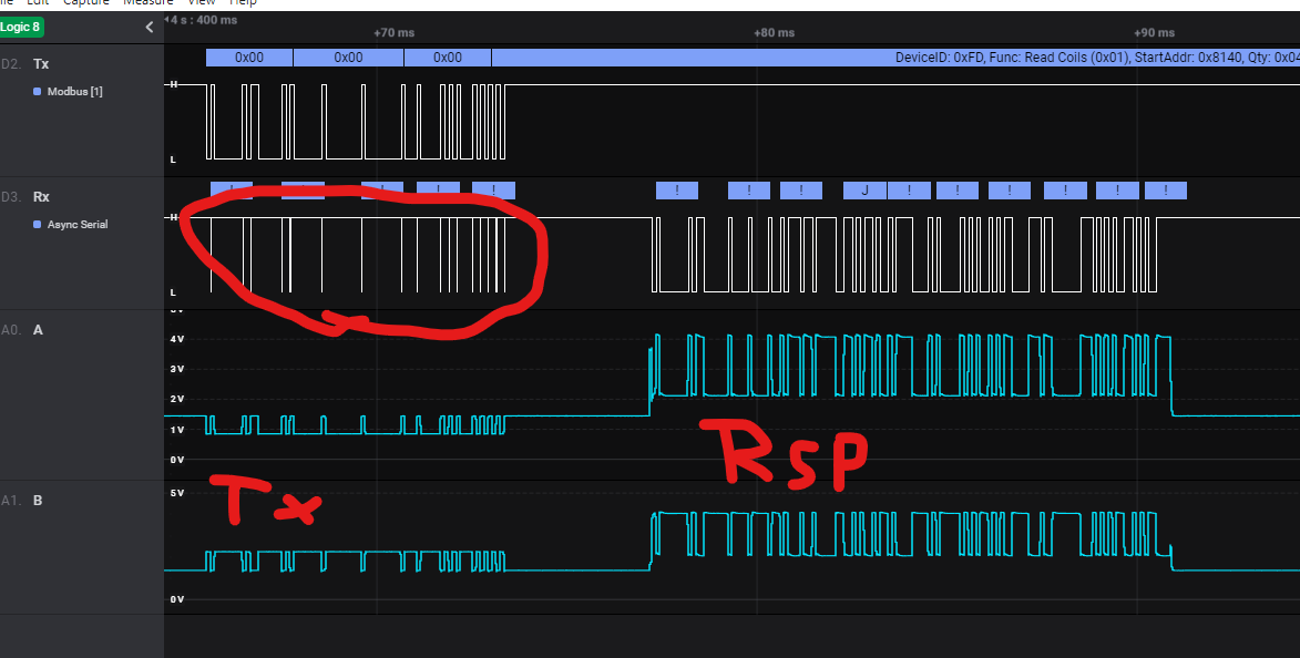
So taking a scan of the hardware lines, with the not working device, TX and RX, A & B - the excitation voltage is 14V
The Tx signal from the Mayfly that looks good,
on the, A &B differential Tx looks good
then there is a response (labeled RSP) back from the Acculevel,
but the decoding of it in ModularSensors isn't workng.
Looking at the Rx to the Mayfly, it is looking like it is getting breakthrough from the Tx section (circled in RED) - possibly upsetting the Modbus decoding
My next step is to look at the Modbus line comms. (oh well though this would take 5minutes, and taken a day to step through to get to here :( , gotta go slowly )
Thought I would just check in with anyone else that maybe using the RS485 hybrid and see if they have seen any issues
@neilh10, YES! And I just solved the problem last week and refined the solution today. I was about to document this, so it's funny to see your post!
I started seeing these issues in the fall with a very inexpensive batch of RS-485 converters that I purchased. So I figured it was inferior quality, and ordered the more expensive SMAKN SCM TTL to RS485 Adapter. Those worked and I had other deadlines, so I didn't think anything of it... until I purchased another batch from SMAKN, and they all had the issue!
The SOLUTION: solder a 120 ohm resistor between the A+ and B- data lines as "termination" to prevent data signal reflections. A 100 or 150 ohm resistor also worked for me.
These are my info sources:
- https://www.maximintegrated.com/en/design/technical-documents/tutorials/7/763.html
- https://www.csimn.com/CSI_pages/RS-485-FAQ.html
Technically, the terminating 120 ohm resistor is supposed to be placed at the end of the sensor chain, but it worked for me to solder it right onto the RS485 adapter board.
I'll try to document this a bit better soon.
This issue has been functionally moved to the https://github.com/EnviroDIY/Mayfly-Modbus-Wing repo. See:
- https://github.com/EnviroDIY/Mayfly-Modbus-Wing/issues/1