rpi-power-monitor
 rpi-power-monitor copied to clipboard
Speed Optimizations
I'm opening this issue to have a specific place for discussion about the measurement/calculation speed, sample rates, and ideas for optimizing the code. I've already began work towards offloading some of the more CPU intensive tasks to Cython, but @kobuki brought an idea of using a native Python library like NumPy that has already done a lot of the underlying optimizations.
Here are some benchmarks I ran on my Pi 3B and my Pi 4 to compare the native Python code as it currently exists in 9375380 (latest master commit) to the Cython optimization that I've been working on for the last week. The measurements were performed only on the collect_data() function, so this is only comparing the speed of reading the ADC and storing the values to a Python list or C array. The more pressing measurement will be from the calculate_power() and rebuild_waves() functions as that's where the majority of maths are performed.
For each of the different tests, I ran about 2 dozen loops and then averaged the results to get an average sampling speed for each test. Only a few lines of output from each test are included for brevity (instead of all 24 lines)
Pi 3B - Python Sampling Rate
Collected 14000 samples in 0.4837 seconds | Overall Sample Rate: 28944.3/s | SPS Per Channel: 4134.9
Collected 14000 samples in 0.4933 seconds | Overall Sample Rate: 28382.9/s | SPS Per Channel: 4054.7
Collected 14000 samples in 0.5253 seconds | Overall Sample Rate: 26649.4/s | SPS Per Channel: 3807.1
Average Per-Channel Sampling Rate: 4088 SPS
Pi 3B - Cython Sampling Rate
Collected 14000 samples in 0.4366 seconds | Overall Sample Rate: 32062.7/s | SPS Per Channel: 4580.4
Collected 14000 samples in 0.4569 seconds | Overall Sample Rate: 30641.9/s | SPS Per Channel: 4377.4
Collected 14000 samples in 0.4524 seconds | Overall Sample Rate: 30945.4/s | SPS Per Channel: 4420.8
Average Per-Channel Sampling Rate: 4514 SPS
Pi 4B - Python Sampling Rate
Collected 14000 samples in 0.4517 seconds | Overall Sample Rate: 30992.6/s | SPS Per Channel: 4427.5
Collected 14000 samples in 0.4586 seconds | Overall Sample Rate: 30529.7/s | SPS Per Channel: 4361.4
Collected 14000 samples in 0.4505 seconds | Overall Sample Rate: 31074.7/s | SPS Per Channel: 4439.2
Average Per-Channel Sampling Rate: 4406 SPS
Pi 4B - Cython Sampling Rate
Collected 14000 samples in 0.4343 seconds | Overall Sample Rate: 32235.4/s | SPS Per Channel: 4605.1
Collected 14000 samples in 0.4340 seconds | Overall Sample Rate: 32258.9/s | SPS Per Channel: 4608.4
Collected 14000 samples in 0.4350 seconds | Overall Sample Rate: 32184.1/s | SPS Per Channel: 4597.7
Average Per-Channel Sampling Rate: 4592 SPS
So, you can see there is a pretty significant improvement on the Pi 3B when using Cython for collecting samples, but not so much on the Pi 4B. There's also not too much of a different between the Cython sampling speeds on the Pi 3B and the Pi 4B.
Still to do...
- Benchmark the actual calculation functions,
calculate_power()andrebuild_waves()(ideally, separately, to get an idea of the performance gain for each function between Python and Cython) - Benchmark a completely different optimization strategy using NumPy instead of Cython (and compare the two).
Continuing from #16 here.
My idea for a similar project was to decouple the 2 main parts of the metering solution:
- Using a producer/sampler process to produce samples as fast as possible and with the lowest possible jitter, which IMO is also very important for accurate processing. Originally I've chosen the MCP3208 for SPI ADC. It can't do timed samples, though, so that must be controlled on the master.
- The producer process could be written in pure C or CPP (maybe Cython) and its only task would be to get samples from the ADC per above. It then would pipe data via memory mapped files or some other buffered method like a Unix domain socket or UDP/TCP socket.
- The producer could run with CPU pinning and at real time priority. It's even possible to allocate a CPU core on the Pi for specific tasks (it's mainly for minimizing jitter and prevention of lost samples).
- The pigpio library is vastly superior to spidev WRT speed - I'd recommend having a look at this library in any case, even for current code.
- The other big part is the consumer or signal processor. This is where it would be possible to use NumPy, for instance. Blocks of data in arrays can be analyzed much more effectively than in pure python. It should become possible to calculate any PQ or transient metric we can think of, up to the capacity of the CPU.
- The other responsibility of the consumer, of course, is passing the cumulative metrics upstream to InfluxDB (or maybe VictoriaMetrics which seems to be a lot faster while using less memory and disk space) for long term storage and representation (in Grafana, like currently).
Additional ideas:
- If "fingerprints" of current waveforms of appliances/devices are available, they could be used to identify them on the electric network when they come on or get turned off. The available samples could be utilized as input in a machine learning system to actually be able to classify them...
- And so on, and so on
I guess the additional ideas would have to wait but it's interesting to see the vast options one can do with a simple data set provided by a relatively simple device :)
From @kobuki in #16:
I've already ordered the PCBs from PCBWay, they should be here in a few weeks per usual. My hands are full with my job nowadays but I'll help with optimizations where I can. It's likely that using a lib with native code support like NumPy will require some major rework in how things are processed. I'll outline my ideas in the new thread.
Great!
WRT clock and ADC resolution. The MCP3208 is capable of 100 kSPS at 12 bits. In the other thread you mentioned an average sampling rate of 4-4.5 kSPS, and thus I think the limiting factor is not the chip but Python itself.
You're correct, but just to clarify: 100K SPS is the maximum speed for all channels when ran at 5V. When the 3208 is ran at 2.7V, the max sampling speed is 50K SPS. This project supplies 3.3V to the chip, so that would put the maximum possible sampling rate somewhere between 50K and about 75K SPS. I don't know how the sampling speed scales with the supply voltage, but my guess would be that it's not linear.
The 4-4.5K SPS from the benchmarks above are per channel - but I also listed the overall SPS in the raw output, which was about 26-27K SPS at worst (Python on the 3B) and 32K at best (Cython on the Pi 4).
I am on the same page as you about Python limiting this speed. From this Cython optimization report, it looks like the SPI communication driver is a big limiting factor (based on all the C code generated if you expand the spi.xfer section in the html file attached. Ironically enough, the spidev library that I am using is just a Python wrapper for C code to read SPI. I would expect that being able to use C to communicate with the SPI bus would bring a HUGE increase in sampling rate, so this is where I would like to start looking into next (when I have time).
@kobuki, I tried implementing the pigpio Python library for comparison to spidev and I'm getting some strange results from pigpio.
Are you familiar with pigpio? This is my first time using it so I think I am missing something. I am running pigpiod with the default settings (no flags).
A SPI baud rate of 8000000 is really the only value that produces somewhat of a sinusoidal waveform when measuring my AC voltage input source. Anything lower or higher produces some wild looking data samples. Here is my code that I'm testing with:
import pigpio
import plotly
import plotly.graph_objs as go
from plotly.subplots import make_subplots
from datetime import datetime

webroot = '/var/www/html'

pi = pigpio.pi()
baud = 8000000
h = pi.spi_open(0, baud)

def collect_data(num_samples, chan):
    samples = []
    for _ in range(0, num_samples+1):
        count, rx_data = pi.spi_xfer(h, [1, 8 + chan << 4, 0])
        value = rx_data[2] << 2
        samples.append(value)
    return samples

def plot_data(samples, chan):
    title = f'{datetime.now().strftime("%d-%m %H:%M")} chan {chan}'
    x = [i for i in range(1, len(samples))]
    fig = make_subplots(specs=[[{"secondary_y": False}]])
    fig.add_trace(go.Scatter(x = x, y=samples, mode='lines'), secondary_y=False)
    div = plotly.offline.plot(fig, show_link=False, output_type='div', include_plotlyjs='cdn')
    home_link = '<a href="/">Back to Index</a>'
    div = home_link + div
    with open(f"{webroot}/{title.replace(' ', '_')}_{baud}.html", 'w') as f:
        f.write(div)

if __name__ == '__main__':
    chan = 5
    samples = collect_data(2000, chan)
    plot_data(samples, chan)
    pi.spi_close(h)
I should be getting a peak value of about 867 at the top of the voltage wave with my setup, but the peak in the pigpio measurements is only about 656. I've attached the html plot that this code generates. Sample Plot.zip
Sorry, not that much - I'll be able to help more when my PCBs arrive. OTOH, I don't think you need pigpiod, that's a daemon providing IO access via socket and command line. You're using the library through Python.
There's a bit-banging code sample here, just ctrl+f for mcp3008, maybe that helps. But something is odd, the 8 Mbps is the upper limit, IIRC. Can you collect the running time of sampling commands? I mean this line:
count, rx_data = pi.spi_xfer(h, [1, 8 + chan << 4, 0])
I did some more testing today with the pigpio library and came to some interesting conclusions. The pigpiod is needed for the Python module as the pigpio docs state:
pigpio is a Python module for the Raspberry which talks to the pigpio daemon to allow control of the general purpose input outputs (GPIO).
The bit-banging example was helpful - thanks for pointing that out. I referenced the bit banging example to utilize the more robust spi_xfer function (the pigpio implementation for bit-banging has a limit of 250 KHz, so it's quite slow).
With a clock speed of 2.5MHz, I'm able to get 14K samples in about 1.83 seconds using pigpio. My existing implementation using spidev and a clock speed of 1.75MHz is able to do the same in about 0.48 seconds.
Can you collect the running time of sampling commands?
Yes, here is the average time it takes to get collect 14K samples from the ADC using both libraries:
# Pigpio sample times
Average time per sample: 0.129ms | Min: 0.121ms | Max: 0.897ms
Collected 14000 samples in 1910.126ms at 2.5 MHz
Effective Sampling Rate:  7.33 KSPS

# Spidev Test Results
Average time per sample: 0.037ms | Min: 0.032ms | Max: 0.257ms
Collected 14000 samples in 568.206ms at 1.75 MHz
Effective Sampling Rate: 24.64 KSPS
My measurements show that spidev is much more efficient than pigpio when it comes to interacting with the SPI bus. Even still, the collection of 14K samples takes the longest amount of time in the entire measurement process, so I'll look to speed that part up with Cython.
Here are the measured times from the heavier calculation functions, calculate_power() and rebuild_waves():
Testing rebuild_waves 10 times
Rebuild Waves Test Results:
  Num Loops: 10 | Min: 13.744ms | Max: 14.077ms | Avg: 13.944ms

Testing calcualte_power 10 times
Calculate Power Results:
  Num Loops: 10 | Min: 63.455ms | Max: 64.081ms | Avg: 63.688ms
Hello everybody.
Sorry to jump into the conversation. I discovered this project late yesterday. David congratulation as I searched a long time this kind of tool (I was also considering Jeedom).
If I understand well, the SPI and data collection seems to fix the worst case. Would you consider a local MCU to make the conversion, and some data manipulation ? It could maybe convert all signals and send only one data stream to the RPI. That would avoid the RPI to make the channel modification and some low level modification. Then the question is : would it be possible to use the internal ADC ?
example : ATTINY1616 has up to 115ksps at 10b, can possibly convert 2 signals at the same time (voltage + current // is it easy to synchronise them ? To be checked), an internal VREF or DAC (to trim this point), and Analoc Comparator to detect when the voltage does pass by 0 (then we can set a timer to start sampling when voltage/current is in theory, and for a PF around 1, close to its max value). Any other MCU could work of course.
By the way, would the project work on a RPI0W ?
Florian
@DuduNord I think the original idea is to only use a Pi for all computations and use only a single ADC for power sampling. There are many projects that use an MCU or ASIC for sampling and processing, and while everything could be improved and it doesn't hurt to replicate existing things, it's not the point here.
I fully understand this point and is fine for me. Having a low lever MCU would require a programming step that is (I must admit) painful. Initially I was fine with both but having all in a PI is indeed better. This is why I have this "idea" in mind.
I don't think programming an MCU is "painful", I personally have no issues with that, it's just not that kind of project :) Also, the computational power of a Pi might allow us to gather a lot more metrics more conveniently than a simple purpose built chip or what a small MCU is capable of. BTW I'm a long time user of OpenEnergyMonitor - that project is one well known example of the MCU approach.
@DuduNord Yes, I am considering an alternate implementation with an MCU after my findings when investigating sampling and processing speeds under this particular Issue. Right now, the full project cannot run on anything older than a Pi 3B+, mainly due to the lack of memory, but also because the CPU clock has a direct impact on the sample rate. It is less memory intensive to run only the measurement and calculation part of the code on older hardware and send/store the values elsewhere, but I haven't tested anything older than a Pi 3B.
I think the Pi is a wonderful environment to run projects on, but it really is a shame that Python on the Pi is the limiting factor here when the processing power of an MCU pales in comparison to the processing power of the Pi. I would imagine that an MCU implementation will allow older hardware to run the project, but the Pi Zero W might be a stretch. We'll have to see when we get there!
I think Pi variants older than 4B/4CM can be safely ignored. Actually, a few months ago I contemplated about an approach that involves an MCU with a fast ADC like many of the STM32 variants or a Teensy 3+. It could sample all channels at high sample rates, free of jitter, and could push data via an async interface like UART (on a high baud rate the Pi supports) or the same on USB, or via USB bulk transfer. That way sampling load can be decoupled from the Pi processes and there's no need to deal with SPI quirks. The new OEM boards also use an STM32 and almost all calculations are done on the MCU. If I wanted to replicate that, I'd buy one of those boards instead, to be honest.
Checking in on this old thread -- just skimmed it. Looks like there is a tie-in here between the sampling rate and irregular performance. Is this still an issue now that 0.2.x is out @David00 ?
I might be missing it, but there is no need to sample faster than Nyquist + ~20% (safety factor). The overhead of doing so will capture more information than is truly necessary if we are just measuring sinusoidal power.
The math on this is nyquist rate + 20% is 60*2 +12 = 132 Hz sampling rate MAX.
Is there a reason to capture faster than the range of 50Hz - 60Hz?
IIRC this discussion was an exploration into speeding up the sampling rate to bring an additional ADC onto the board to increase the channel count. (I've actually already done this with dual MCP 3208s in a related project that I'm preparing to launch)
I believe Nyquist Theorem specifies the minimum sampling rate needed to measure a simple sinusoidal waveform. There are several reasons to sample much faster, though:
- The current waveforms on a circuit are rarely simple sinusoids - they're often complex sinusoids, or not even sinusoidal at all (non-linear loads)
- The harmonics of a wave (signals that oscillate at multiples of the base frequency) may be interesting for some folks and can even be used to identify specific loads, or troubleshoot large systems
- The more data about a voltage and current wave we have, the more accurate the resulting calculations will be, since the power (Watts) is the RMS of the two waves multiplied together, and the energy (Watt-hours) is the integral of the resulting wave.
The sampling rates that we're currently seeing with spidev version 3.6 and my latest v0.2.0 release on a Pi 4 are about 28 kSPS, which is more than sufficient to address the concerns above. Seven channels are sampled, so 28k / 7 = 3.5 kSPS per channel. That would allow sampling up to the 58th harmonic!
However, one thing I do want to work on changing is the way sampling is done in this project. Instead of sampling three CTs, then the voltage, then three more CTs, I'd like to switch to taking CT + voltage sample pairs (one after the other). This would avoid all the complexities in calibrating since there would be a fixed-time interval between every CT and voltage sample. The per-channel sampling rate would go down, but my math shows that it's still more than sufficiently fast.
Hope this is the write thread to ask in, but would the Raspberry Pi Zero 2 W be capable of running this?
I really expect this to work out of the box with the Zero. (Untested, but I could test unless someone else already has?)
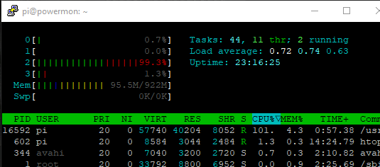
I had to steal the raspberry pi 3 I had originally running this program and have had to swap back to an old raspberry pi 2b. I've offloaded influx and grafana to a separate server and things are running well enough. I've been watching htop to see how things are performing and noticed that the program only ever runs single core (which sits around 100% on my poor old pi2).
As an alternative, or in addition to using the cython implementation, is it possible to modify the python script to use the multiprocessing module that seems to be included in python? Apologies if this is completely wrong, still very new to python.
https://www.digitalocean.com/community/tutorials/python-multiprocessing-example
Cheers
That's awesome to hear that you have it running well on a 2B, with DB and Grafana offloaded!
It is normal for the process to consume 100% of a single CPU core, because it's trying to run as fast as possible through the "sampling, calculation, storage, repeat" process.
I don't think the multiprocessing module would bring much improvement because it's intended to share the load of a CPU heavy task across the multiple cores - assuming the task items can be split up. Since the power monitor is very sequential in nature, it would be tricky to do. I suppose we could split up the sampling and calculation/storage parts of the program into two separate processes, where one samples and the other calculates, but Python has a lot of overhead in creating and managing shared objects between processes. I don't think the gains would be worth the effort.
One thing I will be using multiprocessing for is the new plugin system that I'm setting up to integrate your PR (#101) for MQTT.
Thank you all for your interesting input - I am going to go ahead and close this issue now (both due to inactivity, and relevancy).