Time-Circuits-Display
 Time-Circuits-Display copied to clipboard
Fully Featured Time Circuits Display
Time Circuits Display
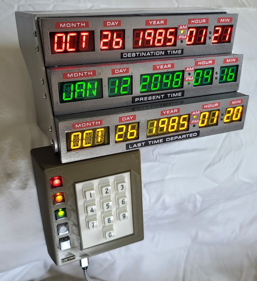
This Time Circuits Display has been meticulously reproduced to be as accurate as possible to the one seen in the Delorean Time Machine in the Back to the Future movies. The LED displays are custom made to the correct size for CircuitSetup. This includes the month 14 segment/3 character displays being closer together, and both the 7 & 14 segment displays being 0.6" high by 0.35" wide.
The Destination Time can be entered via keypad, and the Present Time can keep time via NTP. There is also a time travel mode, which moves the Destination Time to Present Time, and Present Time to Last Time Departed. The startup, keypad dial sounds, and time travel sounds are played using I2S.
To see some things in the code that could use some work, please see here.
Kits
Time Circuits Display kits can be purchased here with or without 3d printed parts.
View the instructions for assembling your CircuitSetup.us TCD Kit
Kit Parts
- 3x Segment displays in (Red, Green, Yellow)
- Gels for displays (Red, Green, Yellow)
- Mounting hardware (37x screws for display enclosure to outer enclosure, display PCB to enclosures, speaker mount, keypad mount, 4x small screws for keypad PCB to bezel mount)
- Connection wiring (3x 4p JST-XH for display I2C, 1 7p JST-XH for keypad)
- ESP32 powered control board
- Programmed ESP32 dev board
- TRW style number keypad (must be disassembled to use number keys, pcb and rubber backing)
- Square LED lenses (2x white, 1x red/amber/green)
- RTC battery
- Small 4ohm 3W speaker
- Display time label stickers
Display Features
- 1x 3 character 14 segment display
- 10x 1 character 7 segment displays
- I2C interface:
- Red (Destination Time) is 0x71
- Green (Present Time) is 0x72
- Yellow (Last Time Departed) is 0x74
- Color:
- Red 630nm
- Green 570nm
- Yellow 587nm
- Measurements: 8.5" x 1.45" (210.82 x 36.83mm)
- Hole Spacing (same as LMB aluminum boxes): 3.75" x 1.28" - 6 total
Control Board Features
- Measurements: 4.53" x 4.12" (115.18 x 104.62mm)
- Real Time Clock
- Ability to get time from NTP (via ESP32 wifi)
- Class D Mono Audio Amplifier - 4ohm
- Manual volume control
- SD card slot (sd card not included)
- 2 additional GPIO outputs (13 & 14)
- 1 SPI output
- On board power supply which can take input from 6-20V DC
- ESD filtering to prevent interference
- Can be powered by ESP32 micro USB port
Control board pinout
- I2C:
- SCL - 22
- SDA - 21
- SD Card (SPI):
- CS - 5
- MOSI - 23
- MISO - 19
- SCK - 19
- Real Time Clock DS3231M (I2C addr: 0x68):
- SQW - 15 (used to blink LEDs every second)
- Keypad PCF8574T (I2C addr: 0x20):
- INT - 4 (can be used as an interrupt, but is not currently)
- Mono sound output I2S / MAX98357
- DIN - 33
- BCLK - 26
- LRCLK - 25
- Other:
- Keypad White LED - 17
- Keypad Enter Button - 16
- Volume - 32
- Status LED - 2 (nodeMCU)