aquacontrol32
 aquacontrol32 copied to clipboard
Pindefinition not Clear
Hey, i am on the way to make for your Project an Fritzing Connection scheme but actually i have a Problem with PIN 12 in Master/devicePinSetup i see the following line
#define SPI_TFT_RST_PIN 12 /* Goes to TFT RESET */
but i cant find anywhere a description of that pin... not on the Pinout on the web or in the PIN-Description of the Arduino ESP 1.0.4 Core Package. can you please describe or change the title to the Original Board Marking like so:
#define SPI_SCK_PIN 25 /* Goes to TFT SCK/CLK, Board PIN IO25*/ #define SPI_MOSI_PIN 32 /* Goes to TFT MOSI, Board PIN IO32 / #define SPI_TFT_RST_PIN 12 / Goes to TFT RESET, Board PIN ??GPIO12/TDI?? / #define SPI_TFT_CS_PIN 4 / Goes to TFT CS,Board PIN IO4 / #define SPI_SD_CS_PIN 0 / Goes to SD CS,Board PIN IO0 / #define SPI_MISO_PIN 39 / Goes to TFT MISO,Board PIN ??SVN/GPIO39?? / #define TOUCH_CS_PIN 33 / Goes to TFT T_CS,Board PIN IO33 / #define TOUCH_IRQ_PIN 35 / Goes to TFT T_IRQ, Board PIN IO35 */
That willl be very helpfull, thank for your Hard work.
If iam ready then you can upload something like this:

Actually this is only Prototyping not the endproduct.
Hi @crazybanane.
You are right, on these boards there is no GPIO12 marking.
On my board it is marked TDI.
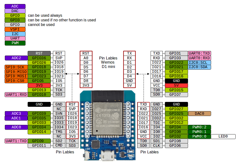
I put GPIO12 there as the pin functions (and silkscreen) can change from board to board.
Hope this helps.
@crazybanane
One thing I saw when testing my board with a scope was a voltage surge (ringing) on the mosfet drains every time the mosfet stopped conducting. I dont recall the exact numbers, but it was quite a high voltage, where the amplitude is a function of the amount of current that is suddenly stopped.
(So you wont see a significant surge it if you just use a single or a few leds for testing)
https://jeelabs.org/2012/12/05/ringing-mosfets/ https://www.mouser.com/pdfdocs/Parasitic_Oscillation_Ringing.pdf
I solved this by putting a n4001 diode between the mosfet drain and +12V with the cathode on the +12V side. This will limit this surge to about 1.1V. See the n4001 data sheet And use a beefy capacitor (or capacitors) to absorb this current.
The diodes are on the bottom in the image.

Hey thanks for answer,
i cant take a look for ringing by my Board because i dont have an Oscillioscope. Actual i dont have Problems with Dimming or Failures like Brownouts. At the moment i have only 1 COB Panel with 70 Watt on Channel 1 but it works super Smooth and Great. I take between ESP Pin for Channel 1 an 220Ohm resistor to Gate and an 10k to GND. On an older Board i had problems with 470Ohms but it was another software. I will test later some other Leds that i have. I think in the near Future i will buy an simple Osci but i dont have too much of plan to work so detailed.
So i think in finished the board for other DIY-people so that they can easier understand the connections if you find failures or big Problems please write me otherwise you can take this to your Project. Hopefully it can Help.
I will correct these Days the German Language files because i found some text that is not suitable, you will got then mail from me.

So then i wish you a Happy New Year or Gelukkig nieuwjaar