EMI_mapper
 EMI_mapper copied to clipboard
A python script using RTL-SDR and OpenCV to create fast 2D electromagnetic maps.
EMI mapping with RTL-SDR and OpenCV
Mapping near-field electromagnetic parasitic emissions is useful for the design, debug and pre-compliance testing of electronic devices. Unfortunately, there is no simple way to make EM scans with sufficient level of details/accuracy, speed and reasonable cost. Hence, I developed this solution to make high-resolution and fast 2D maps of RF EMI for PCBs and more.
You can find more information and details on my project page (including more examples): http://charleslabs.fr/en/project-Electromagnetic+interference+mapping
Prerequisites
Hardware requirements:
- A USB camera (for
camera_emi_mapper.pyscript only), - A 3D printer (for
gcode_emi_mapper.pyscript only), - An RTL-SDR with a (DIY?) near-field probe.
Software dependencies for the python scripts:
- OpenCV (
sudo apt install python3-opencv && pip3 install opencv-contrib-python imutils setuptools) - Pyserial (
pip3 instal pyserial) - pyrtlsdr (
sudo apt install rtl-sdr && pip3 install pyrtlsdr) - numpy, scipy, matplotlib (
pip3 install scipy numpy matplotlib)
These install commands were tested in Ubuntu 19.10.
Method #1: 3D printer EMI mapping
To make an EM map with the 3D printer method:
- Put the DUT on the printer's bed and the near-field probe attached to the carriage,
- Launch the script (optionnal arguments, refer to the help),
- Wait for the printer to scan the board, the result will be displayed as soon as it is done.
Call with python3 gcode_emi_mapper.py -h to view the help (arguments description).
Typical use: python3 gcode_emi_mapper.py -s /dev/ttyUSB0 -f 100 -z 120 -r 5 (start the script using a 100MHz center frequency, zone size of 120mm, resolution 5mm, where 3D printer is connected to the /dev/ttyUSB0 serial port).
Method #2: Camera EMI mapping
To make an EM map with the machine vision method:
- Launch the script (optionnal arguments, refer to the help),
- Properly position the device under test (DUT) in the camera image,
- Press "R" to set the position (the camera and DUT must not move after pressing "R"),
- Put the probe in the frame, press "S", select the probe with the mouse and press "ENTER" to start the scanning,
- Scan the DUT by moving the probe,
- Press "Q" to exit. If a scan was made, the result is displayed.
Call with python3 camera_emi_mapper.py -h to view the help (arguments description).
Typical use: python3 camera_emi_mapper.py -c 1 -f 100 (start the script using a 100MHz center frequency and camera id 1).
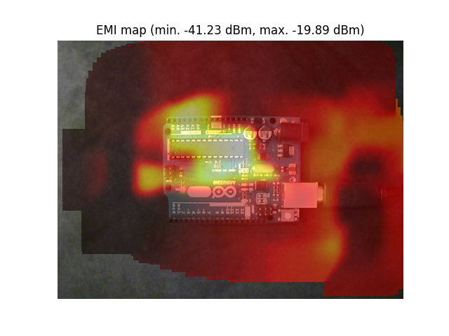
Sample result
This is a scan of an Arduino Uno board performed with this script and a DIY near-field loop probe: